7. Troubleshooting & Support
Consult this chapter in case of unexpected behaviour or if you suspect a product fault.
The correct troubleshooting and support process is to first consult the common issues as described in this chapter.
If you experience problems with VictronConnect, first consult the VictronConnect manual, especially the troubleshooting chapter.
Should these fail to resolve the issue, scan through popular questions and answers regarding your product and ask the community of experts in the Victron Community In case the problem persists, contact the point of purchase for technical support. If the point of purchase is unknown, refer to the Victron Energy Support webpage.
7.1. The is not operational
Once powered up and operational, the controller LED(s) will illuminate or flash and can communicate with VictronConnect via Bluetooth.
Once the charger is powered up, VictronConnect can be used to:
Check the charger status
Check for error messages
Update firmware
Make or change settings
If the unit does not power up, use this chapter to check the possible reasons why the charger is not operational.
7.1.1. Visual check
Before carrying out any electrical checks, visually inspect the charger for damage.
Check for mechanical damage and burn marks.
Note that this kind of damage is usually not covered by warranty.
Are the connecting wires making contact with the plug/terminals?
Are the wires stripped to the correct length and tightened with the correct torque?
See Recommended torque.
Inspect the battery terminals.
If there are burn marks on the terminals or if the cables or connectors are molten, this damage is usually not covered by warranty.
7.1.2. Battery supply check
Check that battery voltage is present at the charger's terminals.
Measure the battery voltage at the charger battery terminals with a multimeter.
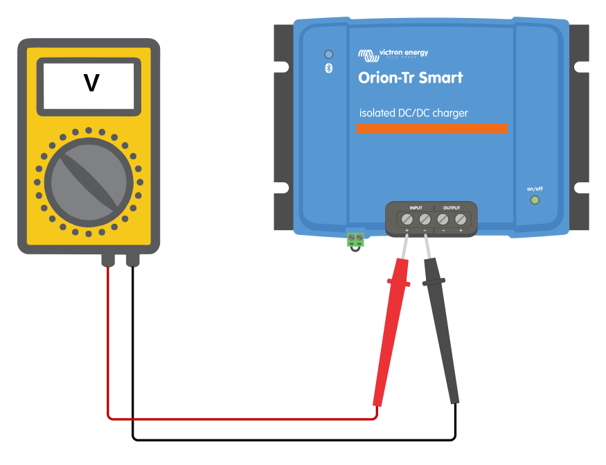 | 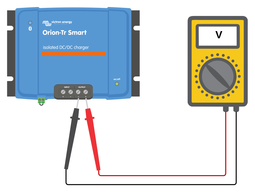 |
The reason for measuring the battery voltage at the charger terminals is to rule out possible problems with the wiring, fuses and/or circuit breakers in the path between the battery and the charger.
Note
The charger is powered from the input side; without input voltage the charger stays off, even if the output battery is connected.
Depending on the result of the measurement, do the following:
Battery voltage | Operational state | Action to take |
|---|---|---|
No voltage | Off | Restore the battery supply. Check the external fuses, and check the wiring for loose or damaged cables and bad crimps. Pull-test the connections. |
Correct voltage | Off | Check for reverse battery polarity; see Reverse battery polarity. If the polarity is correct, there might be a fault with the charger. Contact your Victron dealer or distributor. |
Correct voltage | On | Check for active errors via the VictronConnect app. |
7.1.3. Reverse battery polarity
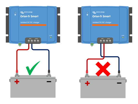
Reverse polarity is when the positive and the negative battery cables have been accidentally swapped. The battery negative has been connected to the positive terminal and the battery positive has been connected to the negative terminal.
Example of correct and incorrect (reverse) battery polarity
 |
Note
Be aware that a red or positive labelled cable might not necessarily mean that the cable is indeed a positive cable. A wiring or labelling mistake could have been made during installation.
Reverse battery polarity can be accompanied with a blown battery fuse (one that is located in the battery cable).
Caution
The is not protected against reverse battery polarity; any damage caused by this is not covered under warranty.
7.2. Battery is not charged
This section lists the possible reasons why the does not charge the battery, and the steps you can take to remedy the situation.
For example:
Issues with the battery or system wiring
Incorrect settings
The is remotely controlled by a BMS or other device via its remote on/off terminal
First, check the status field at the top of the status screen in the VictronConnect app. If charging is disabled, the reason is shown there. This can be because the remote input is inactive, the charger is disabled in the battery settings, or charging is disabled because input voltage lock-out or engine shutdown was detected.
The table below lists the possible messages and the action to take.
VictronConnect message | Action to take |
Remote input inactive | Check that the terminal block for the remote on/off function is plugged in. Check for continuity if a wire loop or simple switch is used between the L and H pins. If a BMS controls the remote input, check that the ATC connection works. If this does not resolve the issue, see Remote terminal is missing, disconnected or external control is active. |
Disabled in settings | Enable the charger in the battery settings. See The charger is disabled. |
Input voltage lock-out | The input voltage is below the lock-out level. See Input voltage lock-out is active. |
Engine shutdown detected | The charger has detected that the engine is not running. See Engine shutdown is detected. |
7.2.1. Remote terminal is missing, disconnected or external control is active
The charger only operates when its remote on/off input is active. Most commonly, this is done with the remote connector with a wire link between the L and H terminals.
 |
Remote on/off connector with wire loop
There are two more ways to activate the remote on/off input; see Remote on/off wiring for the wiring details:
ON when the L terminal is pulled to battery minus or ground (ON switch level < 5V)
ON when the H terminal is pulled to battery plus (ON switch level > 3V)
General remote on/off terminal check
Check that the charger is not being turned off remotely by an external control (see the note below).
Check that the remote terminal connector has been plugged in all the way.
Check that the wire link, or the remote control wires, are making good electrical contact.
Note
In installations where an external device (such as a switch, relay or BMS) controls the remote on/off, the wire loop is not used. Instead, one or two wires connect the remote terminal to the external device. In that case, check that device and its wiring rather than the wire loop. If in doubt whether an external device is turning the charger off, temporarily place a wire link between the L and H terminals to rule this out. Remove the link and restore the original wiring afterwards.
7.2.2. The charger is disabled
Check the VictronConnect app to make sure the charger has been enabled.
 |
VictronConnect enable/disable charger setting
7.2.3. Input voltage lock-out is active
Charging is disabled because the input voltage is below the configured lock-out level. Charging resumes automatically when the input voltage rises above the restart level.
The input voltage lock-out is a protective feature that prevents the from draining the starter battery. If the message appears, the question is whether the lock-out is doing its job or whether it is triggering when it should not.
The input voltage really is low. The engine is off, the starter battery is discharged, or the alternator is not charging. Measure the input voltage at the charger's input terminals, or read it in the VictronConnect app. Charge the starter battery or run the engine.
The lock-out and restart levels are set too high for the system. A smart alternator can operate at a low voltage for extended periods, tripping the lock-out although the engine is running. Compare the configured levels with the actual alternator voltage range; see Automatic engine shutdown detection.
Voltage drop over the input cable trips the lock-out at full charge current, even though the alternator voltage is fine. Check the input cable cross-section and connections, and take the voltage drop into account when choosing the lock-out level; see the calculation example in Engine shutdown detection setup with VictronConnect.
Note
The default lock-out and restart levels differ between charger mode and power supply mode. In power supply mode, the input voltage lock-out determines when the output is active.
7.2.4. Engine shutdown is detected
The has concluded from the input voltage that the engine is not running. If the engine is indeed off, this is correct behaviour and no action is needed.
If the message appears while the engine is running, check the following:
The start voltage is set too high for the alternator, so charging never starts. This typically happens when the wrong alternator type is selected: a smart alternator may never reach the start voltage of a regular alternator. Select the correct alternator type or adjust the start voltage; see Engine shutdown detection setup with VictronConnect.
The shutdown voltage is set too high, so charging stops too early and the battery remains undercharged. Adjust the shutdown voltage; see Engine shutdown detection setup with VictronConnect.
The settings are correct, but the alternator voltage sags below the shutdown voltage as soon as charging starts. This is not a settings problem but a sign that the alternator cannot supply the required power; see Insufficient alternator power.
Note
Some smart alternators legitimately operate at voltages too low for reliable engine shutdown detection. In that case, use an external engine running signal instead of stretching the voltage settings; see the Using an external engine running signal section.
7.2.5. Battery is full
Once the battery is full, the will stop charging or greatly reduce the charge current. This is especially the case when at the same time the DC loads in the system are not consuming any power from the battery.
Be aware that it may also be possible for the to think the battery is full when it is not. This can occur when the charge voltages have been set too low, causing the to switch to the absorption or float stage prematurely.
7.3. Battery is undercharged
This section deals with possible reasons why the is not sufficiently charging the batteries and the steps you can take to check or remedy the situation.
Some signs of undercharged batteries:
The battery takes too long to charge (> 10hrs).
The batteries are not fully charged at the end of the charge cycle.
The charge current from the is less than expected.
7.3.1. Too much DC load
The not only charges the batteries but also provides power for the system’s loads.
The battery will only be charged when the power available exceeds the power being drawn by the loads in the system, like lights, fridge, inverter, and so on.
If the system battery monitor is correctly installed and configured, you can see how much current is going in (or out) of the battery. A positive reading means that current is flowing into the battery, while a negative reading indicates that current is being drawn from the battery.
Turn off all loads and try again to rule this out.
7.3.2. Battery charge voltages are too low
If the battery voltages have been set too low, the batteries will not receive a full charge.
Check if the battery charge voltages (absorption and float) are set correctly. Consult the battery manufacturer’s information for the correct charge voltages.
7.3.3. Battery is almost full
The will reduce its charge current when the battery is almost full.
If the battery's state of charge is unknown, and the current is reducing while the engine is running, it can mistakenly be interpreted as the being faulty.
The first current reduction takes place during the absorption stage.
During the absorption phase, when the battery is almost full, the current is further reduced gradually.
The float stage starts when the batteries are full. During the float stage the charge current is very low.
To find out what the state of charge (SOC) of the battery is, check the battery monitor (if present), or alternatively, check the charge stage the is in.
7.3.4. Battery cable voltage drop
If there is a voltage drop over the battery cables, the will output the correct voltage, but the batteries will receive a lower voltage. Battery charging will take longer, potentially leading to undercharged batteries.
In case there is a large voltage drop, the battery cables and cable connection will need to be checked, and if there are issues, they will need to be rectified.
The voltage drop can have the following causes:
Battery cables with insufficient cross-sectional area
Badly crimped cable lugs or terminals
Loose terminal connections
Bad or loose fuse(s)
Battery cable voltage drop check
This check can only be performed if the is in the bulk charge stage and is charging with full current.
Measure the voltage on the battery terminals of the using the VictronConnect app or a multimeter.
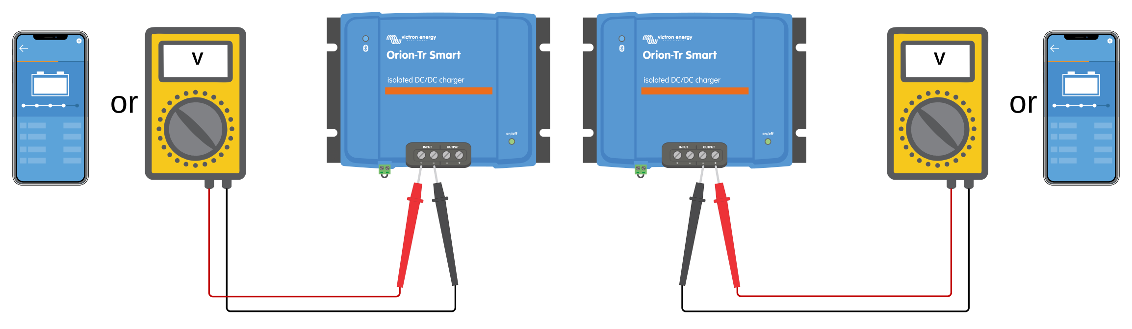
Measure the battery voltage on the terminals of the batteries using a multimeter.
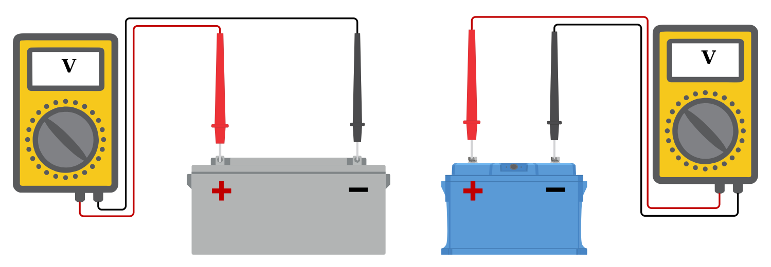
Compare the two voltages to see if there is a voltage difference.
7.3.5. Insufficient alternator power
The can only deliver its full output when the alternator supplies enough power to the input battery. If the alternator cannot keep up, the input voltage collapses as soon as charging starts, and the charger will reduce or stop charging. Because the charger detects a running engine by the input voltage, an overloaded alternator can look identical to a stopped engine.
Typical indications of insufficient alternator power:
The input voltage drops sharply as soon as charging starts, and recovers as soon as charging stops. Monitor the input voltage in the VictronConnect app, or measure it at the charger's input terminals, with the engine running.
Charging repeatedly stops with the message "Charge disabled: Engine shutdown detected" although the engine is running. The sagging alternator voltage falls below the shutdown voltage, which the charger interprets as an engine stop.
Charging cycles on and off: after charging stops, the input voltage recovers above the start voltage, charging restarts, pulls the voltage down again, and so on.
The battery does not reach full charge despite sufficient engine running time.
Possible causes:
The alternator delivers less than its rated output. At idle speed, alternator output can drop to roughly 50% of the rating, and a hot alternator reduces its output further. A worn or slipping belt might have a similar effect.
The charger, or a combination of chargers, is oversized for the alternator. Each charger draws its full input current regardless of what the alternator can supply. This is particularly relevant when several units are connected in parallel.
Voltage drop over undersized or too-long input cables lowers the voltage at the charger's input terminals even when the alternator itself is fine.
What to do:
Compare the alternator's continuous rating - including at idle and at operating temperature - with the total input current of all chargers plus the other loads in the system. If the alternator is undersized, reduce the number of paralleled units, use a lower-power model, or fit a more powerful alternator.
Repeat the test at increased engine speed to confirm idle output is the limiting factor.
Repeat the test with a cold alternator to check whether alternator temperature is the limiting factor.
Check the input cable cross-section and connections against the recommendations in the installation chapter.
Check that the engine shutdown detection settings match the alternator type; see the engine shutdown detection chapter. Note that lowering the shutdown voltage does not solve an overloaded alternator - it only changes when the charger gives up.
7.4. Battery is overcharged
Warning
Batteries that are being overcharged are very dangerous! There is a risk of battery explosion, fire or acid leakage. Do not smoke, create sparks or have open flames in the same room as where the batteries are located.
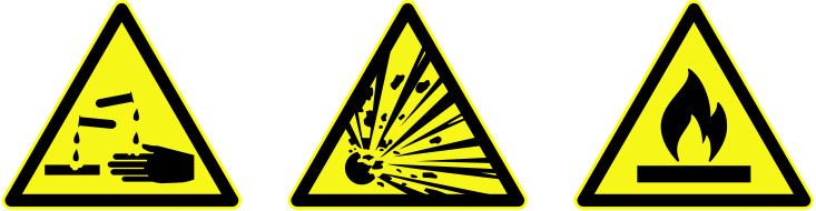
Overcharging batteries will cause battery damage and can be caused by:
Incorrect charge voltage settings
High current and undersized batteries
Battery faults
Too high current, while the battery is not accepting charge anymore because of ageing or prior mistreatment
7.4.1. Battery charge voltages are too high
If the battery charge voltages are set too high, this will cause the batteries to overcharge.
Check if all the battery charge voltages (absorption and float) are set correctly.
The charge voltages have to match the recommended voltages as stated in the battery manufacturer's documentation.
7.4.2. Battery old or faulty
A battery that is at the end of its service life or has been damaged by incorrect use can be prone to being overcharged.
A battery contains a number of cells that are connected in series. When a battery is old or has been damaged, a likely scenario is that one of these cells is not operational anymore.
When the faulty battery is charged, the damaged cell will not accept charge, and the remaining cells will receive the broken cell’s charge voltage and thus will be overcharged.
To fix this, replace the battery. In case of multiple battery systems, replace the whole battery bank. Mixing batteries of different ages in one battery bank is not recommended.
It is hard to tell what exactly happens to a battery during its lifetime. If the system also contains a Victron battery monitor, the historical battery data can be accessed. This will give a complete picture of the battery history, and it can be determined if the battery is near the end of its service life or has been abused.
To check if the battery is close to its cycle life:
Find out how many charge and discharge cycles the battery has been subjected to. Battery lifetime correlates to the number of cycles.
Check how deep the battery has been discharged on average. A battery will last for fewer cycles if deeply discharged, compared to more cycles if discharged less deep.
Refer to the battery datasheet to find out how many cycles at what average discharge the battery is capable of. Compare this with the battery history and determine if the battery is near the end of its service life.
To check if the battery has been misused:
Check if the battery has been totally discharged at all. Total and very deep discharge will damage a battery. Check the battery monitor setting history on the VRM portal. Look for the deepest discharge, the lowest battery voltage, and the number of full discharges.
Check if the battery has been charged with too high voltage. Very high charge voltage will damage the battery. Check the maximum battery voltage and the high voltage alarms in the battery monitor. Check if the measured maximum voltage has exceeded the battery manufacturer's recommendations.
7.5. Full rated output not reached
There are a few reasons why the is not reaching its full rated output.
Alternator rating (during idling) too small
If the alternator power rating is less than the nominal power rating, it cannot output more power than the connected alternator can provide. To determine whether the alternator is the limiting factor, see Insufficient alternator power.
Temperature protection active
When the heats up, eventually the output current will derate. When the current is reduced, naturally the output power will reduce as well.
The is operational up to an ambient temperature of 55°C, with full rated output up to 40°C when mounted on a vertical surface with the terminals facing downwards and sufficient free space for ventilation. Above 40°C, the output current derates by 3% per °C.
If the is located in a closed enclosure, such as a cabinet, make sure that cold air can enter and hot air can leave the enclosure. Mount vents in the enclosure.
For very hot environments consider mechanical air extraction or provide air conditioning.
7.6. Bluetooth connection issues with VictronConnect
In normal operation, the blue Bluetooth LED blinks every 0.8 seconds when the Orion-Tr Smart DC-DC Charger is advertising and available for connection in VictronConnect. See the LED Indicators section for the meaning of the different LED codes.
If the Bluetooth LED is not blinking, check the following.
Blue LED status | LED duration | Action to take |
|---|---|---|
Off | - |
If none of the above applies, the unit may be faulty. Submit a warranty claim. |
Blinking | Every 0.8 seconds |
|
For all other connection problems, please consult the VictronConnect manual for troubleshooting Bluetooth connection issues. | ||
7.7. Error codes
The error codes are displayed in the VictronConnect app.
For the most up-to-date version of this list, see this link: https://www.victronenergy.com/live/mppt-error-codes.
This error will auto-reset after the battery voltage has dropped. This error can be due to other charging equipment connected to the battery or a fault in the charge controller.
Power terminals overheated; check wiring, including the wiring type and type of strands, and/or fasten bolts if possible.
This error will auto-reset.
This condition indicates an over-current condition on the battery side. It can occur when a battery is attached to the unit using a contactor. Or in case the charger starts up without a battery connected but connected to an inverter with a large input capacitance.
This error will auto-reset. If the error does not auto-reset, disconnect the charge controller from all power sources, wait 3 minutes, and power up again. If the error persists, the charge controller is probably faulty.
If the unit does not work and error 116 pops up as the active error, the unit is faulty. Contact your dealer for a replacement.
If the error is only present in the history data and the unit operates normally, this error can be ignored safely. Explanation: when the units power up for the first time in the factory, it does not have calibration data and an error 116 is logged. Obviously, this should have been cleared, but in the beginning, units left the factory with this message still in the history data.
The charger cannot read its configuration and stopped.
This error will not auto-reset. To get it working again:
First, restore it to factory defaults (top right in VictronConnect, click on the three dots).
Disconnect the charge controller from all power sources.
Wait 3 minutes, and power up again.
Reconfigure the charger
Please report this to your Victron dealer and ask him to escalate it to Victron, as this error should never happen. Preferably include firmware version and any other specifics (VRM URL, VictronConnect screenshots or similar).