5. Automatic engine shutdown detection
The automatic engine shutdown detection simplifies the system by detecting whether the engine is running, without wiring additional switches or sensors. The factory default setting will work with most conventional and smart alternators but can be re-configured with the VictronConnect App.
The detection is based on the alternator voltage. Conventional alternators will generate a fixed voltage (e.g. 14V), whereas the voltage of smart alternators can vary between 12.5V to 15V (for a 12V system). Smart alternators in a regenerative braking system often show large voltage variations.
Engine shutdown detection is only active in charger mode. The feature can be configured, disabled and reactivated as described in the Engine shutdown detection setup with VictronConnect section. In power supply mode, the Input voltage lock-out determines when the output is active.
In installations where the alternator voltage does not give the detection enough to work with, an external engine running signal can be used instead; see the Using an external engine running signal section.
Note
The engine shutdown detection is updated from software version v1.05 onwards.
5.1. How it works
The following procedure describes the operation of the engine shutdown detection sequence.
 |
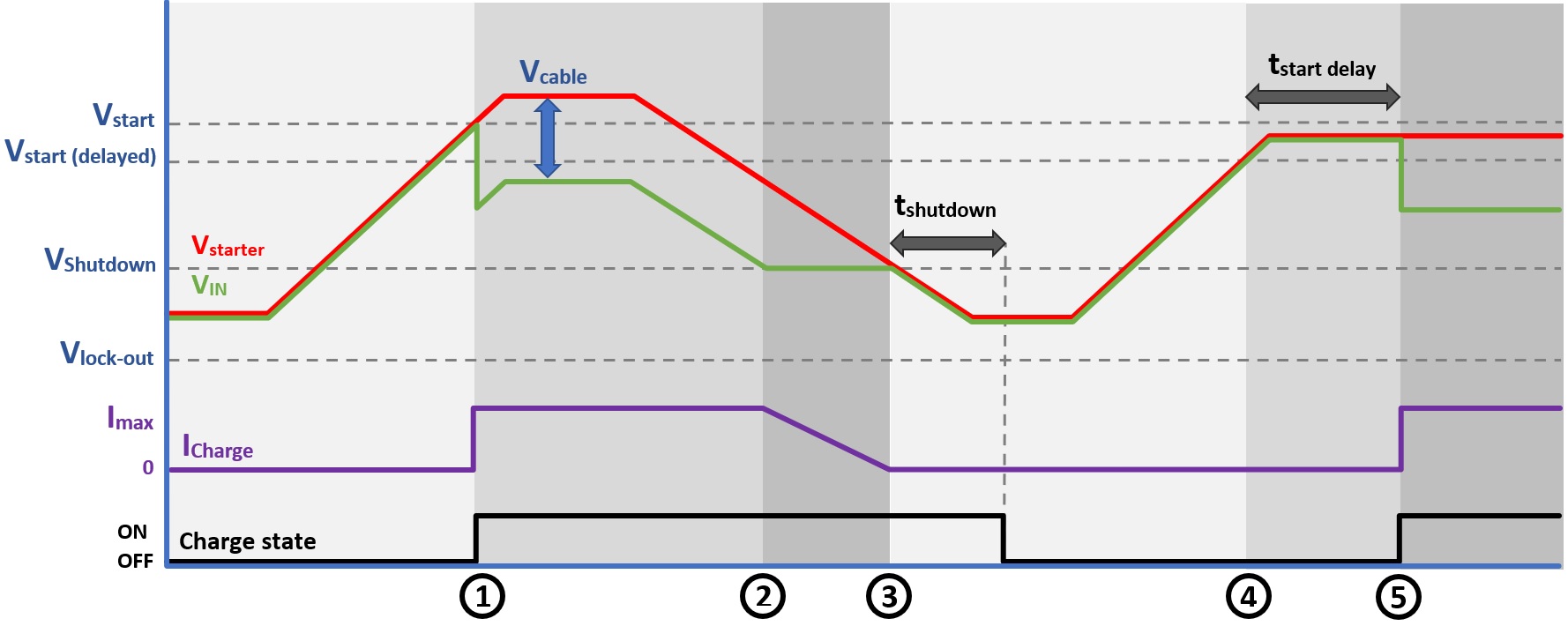 |
Figure 8: Engine shutdown detection sequence
0 → 1: If the engine runs, the alternator voltage will ramp up. When Vstarter > Vstart, charging is enabled.
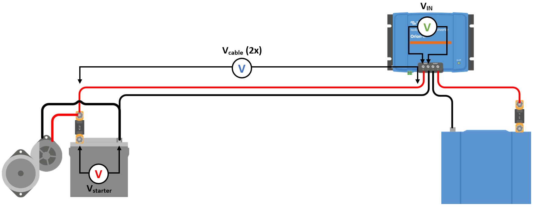
1 → 2: The input current produces a voltage across the input cable (Vcable); this voltage reduces the voltage measured by the charger (VIN). If VIN > Vshutdown, the charger will operate at Imax.
2 → 3: If VIN ≤ Vshutdown, the charge current will be reduced to prevent VIN to drop below Vshutdown.
3 → 4: If VIN < Vshutdown for longer than 1min (tshutdown), “engine off” is detected and charging is disabled. If VIN > Vshutdown before tshutdown runs out, charging remains enabled.
4 → 5: If Vstart(delay) < VIN < Vstart, charging is enabled after tstart delay (configurable).
5.2. Engine shutdown detection setup with VictronConnect
Open VictronConnect and press the cog symbol  to enter the settings.
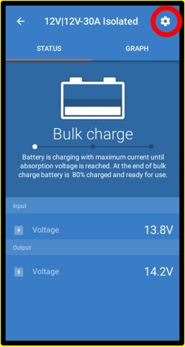 | 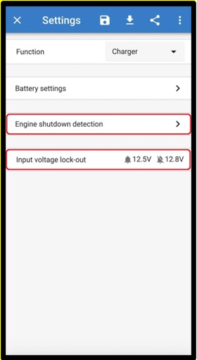 | 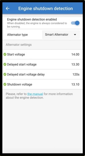 | 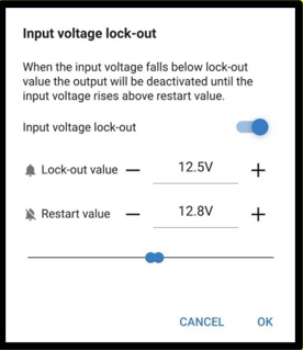 |
Figure 9: Engine shutdown detection setup menu
The following settings can be changed with VictronConnect:
Notice
The default values displayed are for 12V input models. These values are scaled based on the model's input voltage. For example, for 24V input models, the default values in the manual should be multiplied by 2, and for 48V models, they should be multiplied by 4.
Engine shutdown detection enabled: The engine shutdown detection is always enabled by default when the charger mode is selected. When it is disabled by the user or when power supply mode is selected, the engine is considered to be running, so no shutdown detection will take place. Leave the engine shutdown detection enabled when an external engine running signal is connected: the signal only forces charging on, and disabling the detection makes the charger charge continuously regardless of the signal. See the Using an external engine running signal section.
Alternator type: The alternator type can be selected between “Smart Alternator”, “Regular Alternator”, and “User defined”. When the “Smart Alternator” option is selected, the default values for the smart alternator are/will be applied to the engine shutdown detection settings. The same will happen when the “Regular Alternator” option is selected. When any settings differ from the default values of the last two options, the “User defined” option will be selected. Default: “Smart Alternator”.
Start voltage (Vstart): At this level, charging starts immediately.
Delayed start voltage (Vstart(delay)): Smart alternators can generate a lower voltage when the engine is running; therefore, a lower start level is necessary for these systems. To ensure that the starter battery is recharged after starting the engine, charging of the auxiliary battery is delayed during this condition. The energy used during starting must be replenished to ensure that the starter battery remains properly charged.
Delayed start voltage delay (tstart delay): Recharge time for the starter battery during start level (delayed). Example: If the starter draws 150A for 5sec to start the engine, about ~0.2Ah is drawn from the starter battery. If, during engine idling, the alternator can only generate 20A, it takes 150A/20A x 5sec =37.5sec to recharge the starter battery.
Shutdown voltage (Vshutdown): This level corresponds with the engine being off. This keeps the starter battery fully charged and provides a hysteresis with respect to the start level. The hysteresis must be large enough to prevent VIN to drop to Vshutdown , which would result in charge current reduction. Action will be taken after tshutdown runs out (1 minute); this allows charging during temporary low voltage conditions.
The default values depend on the selected alternator type. Values are given as 12V / 24V / 48V input model.
Setting | Smart Alternator | Regular Alternator |
Start voltage (Vstart) | 14V / 28V / 56V | 14V / 28V / 56V |
Delayed start voltage (Vstart(delay)) | 13.3V / 26.6V / 53.2V | 13.8V / 27.6V / 55.2V |
Delayed start voltage delay (tstart delay) | 120s | 120s |
Shutdown voltage (Vshutdown) | 13.1V / 26.2V / 52.4V | 13.5V / 27V / 54V |
Range for engine start/shutdown levels:
12|12; 12|24; 12|48: 8 to 17V
24|12; 24|24; 24|48: 16 to 35V
48|12; 48|24; 48|48: 32 to 68V
Setup input voltage lock-out: Input voltage lock-out is the minimum level at which charging is allowed; below this level, charging stops immediately. Default (in charger mode): lock-out: 12.5V / restart: 12.8V. Default (in power supply mode): lock-out: 10.5V / restart: 12V.
Warning
When ‘forced charging’ is enabled, current will be drawn from the starter battery if the engine is not running. Setting the lock-out level very low can result in a depleted starter battery.
To set up input voltage lock-out, two criteria are important:
Minimum alternator voltage: A smart alternator can operate at very low alternator voltage (<12.5V), e.g. when the vehicle accelerates. This low voltage is allowed during tshutdown as shown in “engine shutdown detection sequence 3→4”. If charging must remain enabled during this period, the lock-out level must at least be set below the minimum alternator voltage.
Notice
If the low voltage period exceeds tshutdown charging will be disabled on engine shutdown detection.
Voltage drop across the input cable: As seen in “engine shutdown detection sequence 1→3”, VIN will be lowered by Vcable. When the alternator voltage drops fast (smart alternator), the charge control needs some time to reduce the charge current and keep VIN at Vshutdown. During this time Vcable must not trip the voltage lock-out. Therefore, the lock-out value should be: Vlock-out ≤ Vshutdown – Vcable.
Example: Calculate the input cable voltage drop:
Distance between starter battery and charger: 5m.
Vshutdown= 13.1V. Recommended wire gauge: 16mm2.
Cable resistance: ~1.1mΩ/m @20°C, thus Rcable = 1.1mΩ x 10m (2x 5m) = 11mΩ.
A 12|12-30A Smart Charger will draw about 35A from the input when running at full capacity, resulting in:
Vcable = 11mΩ x 35A = 385mV.
Vlock-out ≤ Vshutdown – Vcable = 13.3V – 385mV ≈ 12.9V.
Notice
Cable connections, external fuses, temperature, etc., influence the total cable resistance.
5.3. Setup for Euro 6 vehicles
Euro 6 vehicles use a smart alternator that is managed by the vehicle. While driving, the alternator management system decides whether the alternator is needed, based on the electrical demand of the vehicle and on how much energy can be recovered during braking. As a result, the charge voltage is not constant: it can vary roughly between 12.5V and 15V in a 12V system, and the alternator can be switched off completely for a while. When the alternator is switched off, the voltage at the starter battery falls back to the static battery voltage (~12.6 V). The engine shutdown detection reads that voltage and can conclude that the engine has stopped, even though the vehicle is still driving. During this phase, the will not charge, potentially resulting in an undercharged auxiliary battery.
Note
The voltages mentioned in this section apply to 12V input models. For 24V input models, scale the values accordingly.
The alternator management system also reacts to the electrical demand in the vehicle. When enough loads are present, the alternator produces at least a float-level voltage (~13.8V), which the engine shutdown detection recognises without difficulty. If the base load in the system is sufficiently high, the alternator remains active for most of the drive and the automatic detection works well.
Whether this happens depends on the vehicle and on the installation, so the engine shutdown detection sometimes needs fine-tuning. Four settings are available for this in the VictronConnect App: the start voltage, the delayed start voltage, the delayed start voltage delay and the shutdown voltage. See the Engine shutdown detection setup with VictronConnect section for a description of each setting. Lowering the start and shutdown voltages makes the detection tolerate the lower charge voltages of a smart alternator, at the cost of a smaller margin above the static battery voltage.
Be aware that charging strategies differ from vehicle to vehicle, even within the same brand and model. Owners of the same vehicle model may find that some can successfully utilise engine shutdown detection, while others experience undercharged auxiliary batteries.
In a vehicle where the alternator is switched off for long periods and the base load is low, fine-tuning may not be enough to keep charging going. An external engine running signal can be used instead; see the Using an external engine running signal section.
5.4. Using an external engine running signal
The engine shutdown detection determines whether the engine is running from the input voltage. In some vehicles the alternator voltage does not follow the engine, for example when a smart alternator is switched off for long periods while driving. In such an installation, a signal from the vehicle can be used to tell the that the engine is running.
Such a signal is connected to the remote L-pin. While the signal is present, it overrides the engine shutdown detection and charging is forced on. While the signal is absent, the returns to the engine shutdown detection, which decides whether the engine has stopped. For the wiring, see the External engine running signal wiring section.
Note
Leave the engine shutdown detection enabled in the VictronConnect App when an external engine running signal is used. The signal only forces charging on; stopping charging when the engine is off remains the task of the engine shutdown detection.
Warning
When the engine shutdown detection has been switched off in the VictronConnect App ('forced charging'), current will be drawn from the starter battery even if the engine is not running, regardless of any external signal that is connected. The input voltage lock-out is then the only limit left to disable charging automatically; make sure this level is not set too low — in most 12V systems 12.5V is sufficiently low.
Which signal to use
Several sources can provide an external signal. Each has its drawbacks, which should be understood before choosing one.
Vehicle engine running signal:
This is the most accurate source, as the signal comes from the vehicle's own system and follows the engine directly. However, accessing this signal can be challenging, and it may require activating the function in the vehicle's software.
Pulled-low engine running signal:
Some vehicles provide an engine running signal that is pulled to ground (battery minus) while the engine is running. This is the opposite of what the L-pin expects, so the signal cannot be connected to the L-pin directly. A relay is used to convert it; see the External engine running signal wiring section.
D+:
The D+ signal, which comes from the alternator, indicates that the alternator is active. In Euro 6 vehicles this signal is often no longer provided, making it unusable. There are D+ simulator devices that generate a signal based on the alternator voltage, but these work from the same voltage that the engine shutdown detection already measures, so in an installation where the alternator voltage is the problem they offer no advantage.
Ignition switch:
It is common to use the ignition switch to enable charging. While this method is not inherently wrong, it allows the to discharge the starter battery when the ignition is on but the engine is not running. This requires the user to be vigilant about when charging is permitted, to avoid a flat starter battery. Therefore, we do not recommend using the ignition switch to enable charging.
Vibration sensor:
This device generates a voltage when it detects engine vibrations. Be aware that external vibrations, such as those from transport on a boat or train, or even loud music, can be mistaken for a running engine. To mitigate this, power the vibration sensor from an ignition-switched source, so that charging is only permitted when both the ignition is on and vibrations are detected.
CAN bus interface with engine running output:
This device reads the engine running command broadcast on the CAN bus and converts it into an on/off signal. This requires tapping into the CAN bus, and the ease of access varies between vehicles.