7. Wiring Diagrams
In this section:
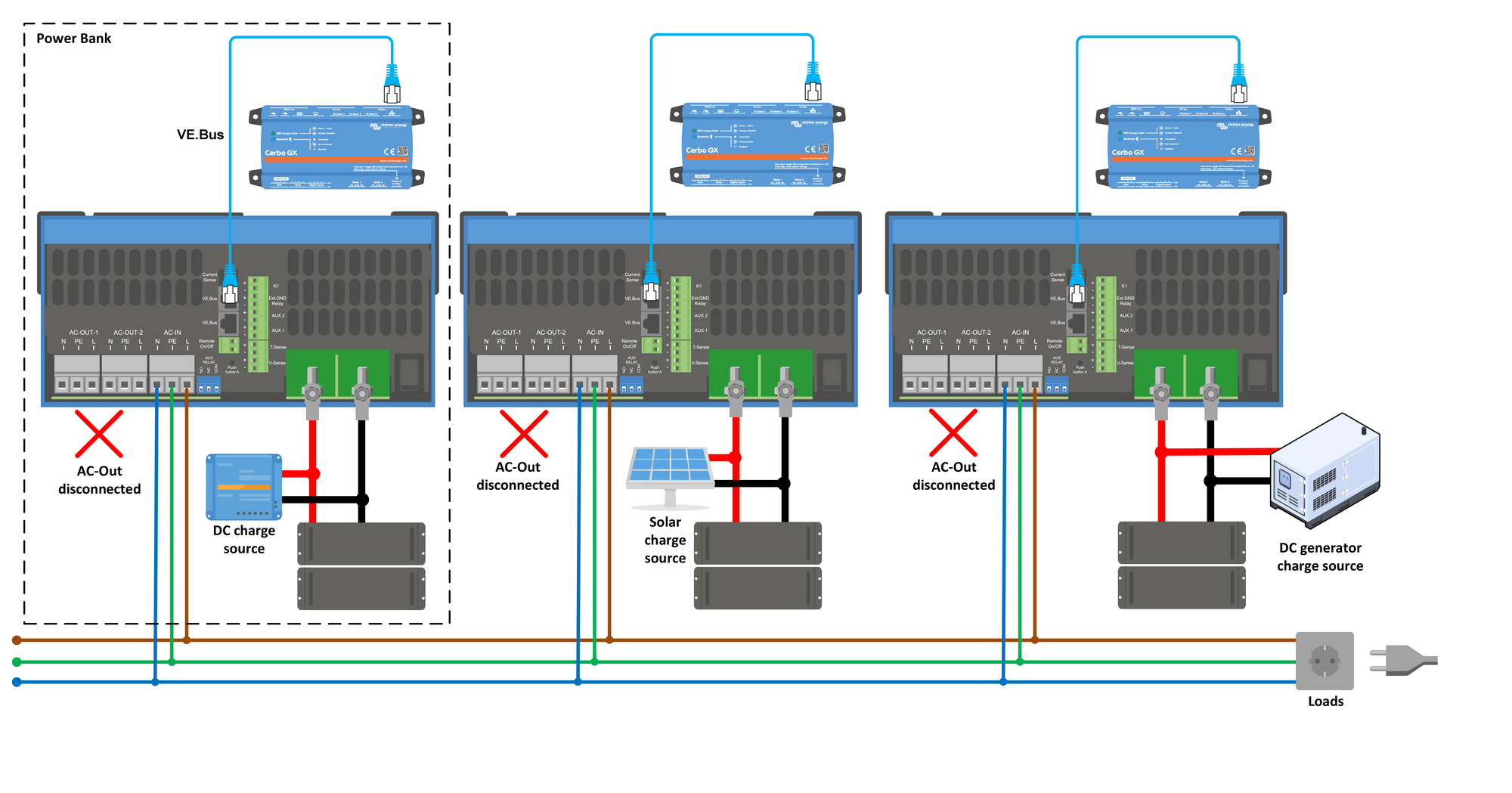
This diagram shows three Power Banks in a single phase Microgrid system. Each Power Bank is connected to the Microgrid AC bus via the AC input of the inverter/charger, and has an independent DC charge source. AC output is not used, and not connected. VE.Bus is used to connect each Inverter/Charger to its own GX device.
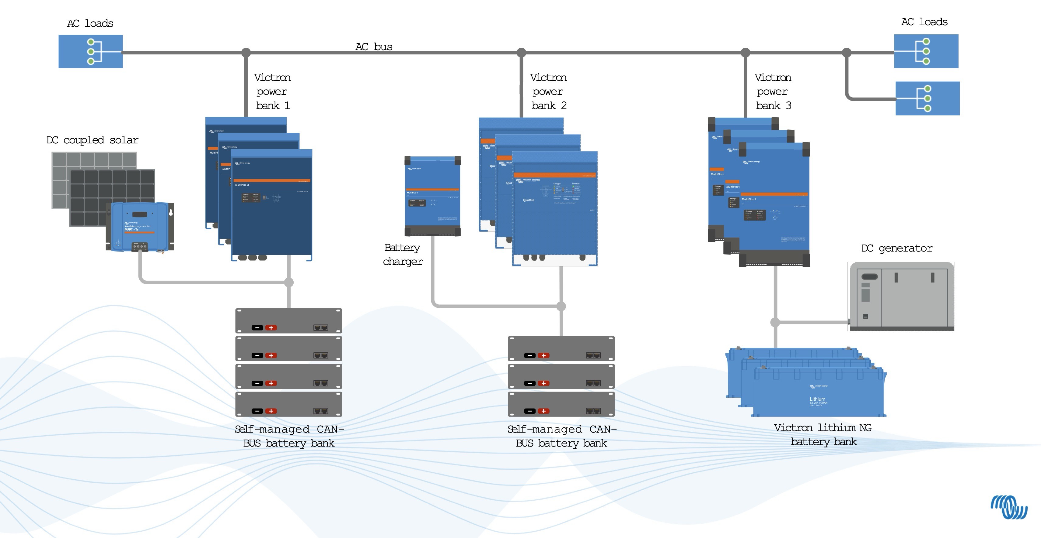
This single line diagram shows nine inverter/chargers with different battery configurations in a three phase Microgrid. In this example, Power Bank 2 utilises an additional MultiPlus that is not configured for Microgrid to charge batteries from an AC source.