3. Installation
Warning
Microgrid systems with one or multiple Victron Power Banks are advanced power systems and exceed the complexity of standard parallel or multiphase installations. Installation and commissioning must only be performed by trained and experienced professionals.
Before initial power-up, carefully verify all AC and DC wiring. Wiring errors can lead to equipment damage and unsafe operating conditions.
Each Victron Power Bank in a Microgrid system can be designed largely according to the established principles of a standard VE.Bus inverter/charger system or MultiPlus / MultiPlus-II External Transfer Switch application.
Each Power Bank:
May be configured as a single-phase or multi-phase inverter/charger system.
May include multiple inverter/chargers in parallel per phase.
Is connected to one common battery bank forming a shared DC bus.
May include a GX device for monitoring and control.
All inverter/chargers within one Power Bank must be interconnected via VE.Bus.
Important
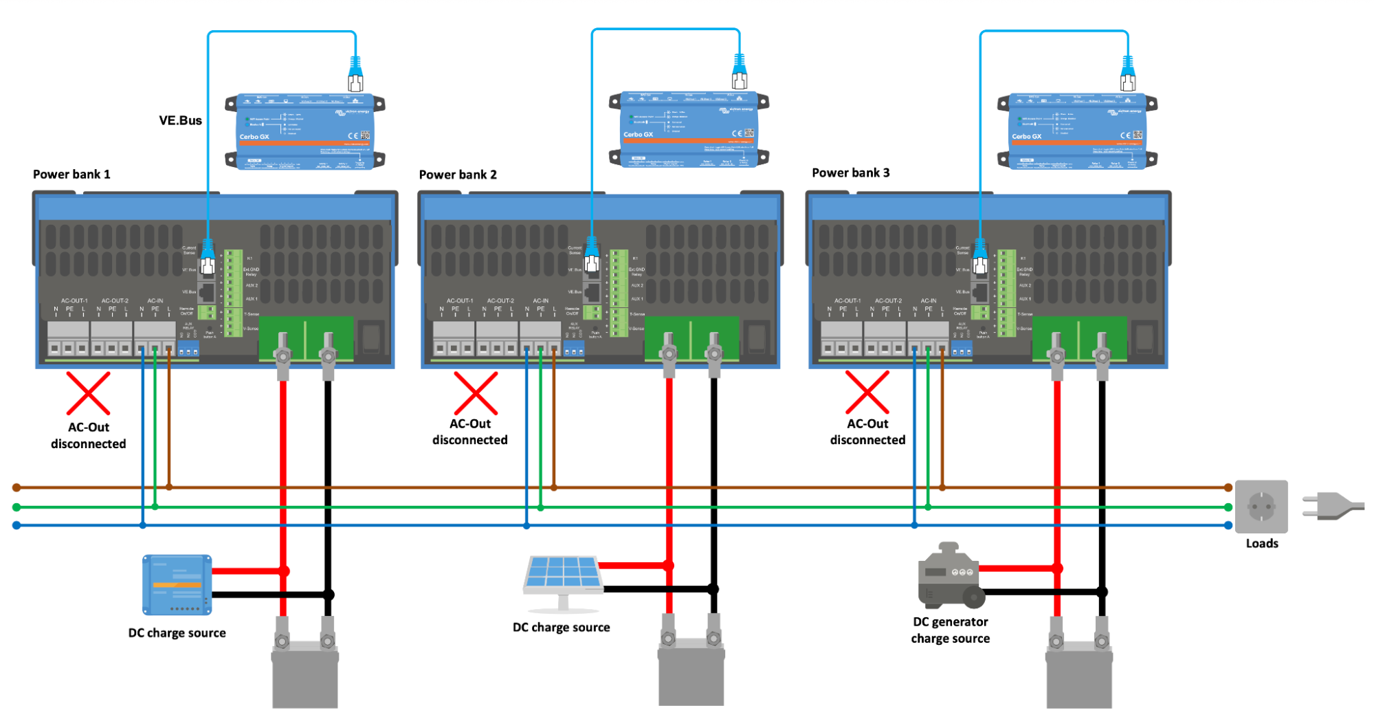
There is no VE.Bus connection between different Power Banks.
3.1. Connection of the AC cabling
The Microgrid AC bus is connected to the AC input of the inverter/chargers:
For MultiPlus and MultiPlus-II, use AC-IN.
For Quattro and Quattro-II, use AC-IN-2.
For an External Transfer Switch configuration, follow the notes below.
This AC connection serves as the interface to the shared Microgrid bus and is used both to supply and stabilize the AC system in Hybrid Droop mode.
Important
AC-OUT-1 and AC-OUT-2 are not used in this application and must remain disconnected.
Combining Microgrid with External Transfer Switch function
The use of an External Transfer Switch is supported in Microgrid systems, and it is permitted to power the contactor from either AC-IN or AC-OUT.
It requires inverter/chargers running firmware with the s98 subversion number (instead of the s97 firmware). Refer to the Configuration chapter for firmware selection and setup details.
When implementing an External Transfer Switch in a Microgrid system, the following additional considerations apply. The supply source of the External Transfer Switch directly affects system behavior:
If the External Transfer Switch is powered from AC-IN, the system cannot black-start the Microgrid.
If the External Transfer Switch is powered from AC-OUT, black-starting is possible. However, the system will not reconnect to the Microgrid if the batteries are fully depleted.
To allow both, black-start capability, and startup with a fully discharged battery, a design solution must be implemented that ensures the External Transfer Switch can always be energized, independent of battery state or AC bus condition.
The supply concept of the External Transfer Switch must therefore be carefully considered during system design.
3.2. DIP switch configuration
Some inverter/charger models require a manual DIP switch change to allow Microgrid (Hybrid droop) operation.
By default, these units will not close the internal AC input relay unless voltage is detected on AC IN. For Microgrid operation, this behavior must be overridden so the unit can close the AC input relay even when no voltage is present on AC input.
This applies to:
MultiPlus 5000 VA and larger (excluding 20k model)
Quattro 3000 VA and larger
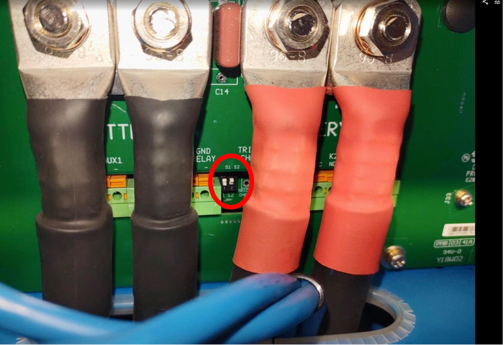
Set the DIP switch "S2" on the connection board to ON (switch in the up position).
For the MultiPlus 2000 VA, MultiPlus 20000 W, MultiPlus-II range and Quattro-II range, no such change is required.
Refer to the marked position in the following photo.
3.3. Three-phase systems and grounding concept
In three-phase Microgrid systems:
L1, L2, and L3 of all Power Banks are connected to the corresponding phases of the shared AC bus.
A common neutral conductor must be used across the entire Microgrid AC bus.
In Microgrid operation, the AC bus neutral is not internally bonded to protective earth (PE) by the inverter/chargers. The system therefore operates with a floating neutral, unless an external neutral-to-earth connection is established.
If the installation requires a defined earthing system, the neutral-to-earth bonding must be implemented externally at only one point in the Microgrid system – in accordance with local regulations and system design requirements.
Caution
Proper grounding and protection concept design remains the responsibility of the system designer.
3.4. Three-phase load balancing
It is recommend to keep the load power difference between phases to a maximum of 30% of the max power of a phase.
When the imbalance is larger a difference in voltage between the phases will occur.
The Microgrid will continue to function with this difference in voltage, however some three-phase loads may not operate correctly.
3.5. Wiring example