4. Configuration
4.1. Upgrade to s97 / s98 VE.Bus firmware
The MultiPlus, MultiPlus-II, Quattro or Quattro-II units require application-specific VE.Bus firmware, identified by the s97 subversion number – and s98 subversion number when using the External Transfer Switch functionality.
Upgrade procedure:
Download the xxxxyyy-s97.vff or xxxxyyy-s98.vff file from https://professional.victronenergy.com/
Install the firmware using VEFlash, the VictronConnect app, or the VRM Portal.
Ensure you select the xxxxyyy-s97.vff or xxxxyyy-s98.vff file during the firmware upgrade.
Repeat the process for all MultiPlus, MultiPlus-II, Quattro or Quattro-II units.
Caution
CAUTION: Never use MultiPlus or MultiPlus-II unit with standard or s97 firmware in an "External transfer switch" application. This will cause the system to connect to the AC input and likely trigger the current protection on that measurement-only circuit.
4.2. VE.Bus System configuration
Each Victron Power Bank is built from one or multiple VE.Bus inverter/chargers. The inverter/charger configuration follows the same well-known principles as a standard VE.Bus system.
As with conventional Victron installations, a Power Bank can be designed as:
A single-phase system
A three-phase or split-phase system (depending on the models and market)
With multiple inverter/chargers in parallel per phase
The configuration principles are identical to those commonly used with MultiPlus, Quattro, MultiPlus-II, and Quattro-II systems.
In the following sections, the configuration of a three-phase system consisting of nine inverter/chargers in total (three units per phase), and using an external transfer switch, is shown as an example.
Three-phase, parallel configuration example
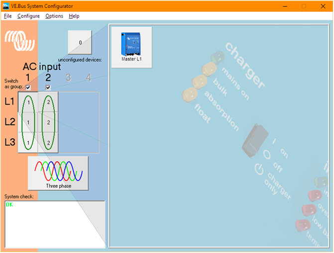
When configuring Power Banks that have parallel, split phase, or three phase configurations use the "VE.Bus System Configurator" to set up the system.
Single VE.Bus Inverter/Charger Power Bank systems should proceed straight to the VEConfigure section.
Three-phase, split phase & parallel system configuration procedure
Configure all phase masters in AC input group 1.
Configure all slaves in AC input group 2.
(Note: assigning slaves to AC input group 2 is specific to external transfer switch applications. For systems using internal transfer switches both masters and slaves should be configured in AC input group 1)
This screenshot shows the master on the first phase of a three phase system with 3 parallel inverter/chargers on each phase.
Right clickt on the "Master L1" tile, select VEConfigure, and follow the directions in the next section to program the master.
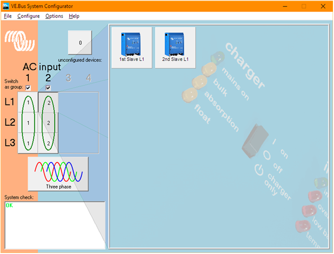
This screenshot shows the slave parallel VE.Bus inverter/chargers on phase 1 of a three phase system.
As with the masters, right click on the tiles and select VEConfigure to program the slaves successively.
4.3. Inverter/Charger configuration
Use "VEConfigure" to configure each Inverter/Charger unit.
Configuration procedure:
Ensure the s97 or s98 firmware version is installed, and all software versions are up to date.
Navigate to the “General” tab.
In case of an External Transfer Switch setup with the s98 firmware:
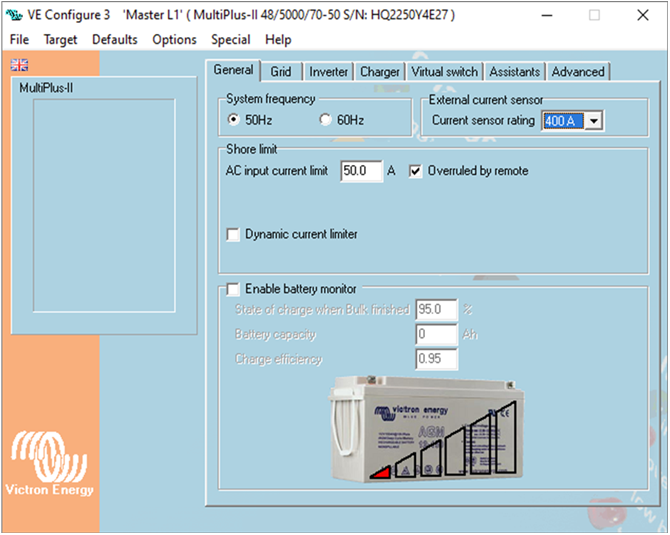
For all phase master units, set the "Current sensor rating" to 100 or 400A, matching the current sensor's current rating.
For all slave units, set the "Current sensor rating" to 100A, regardless of the current sensor's current rating.
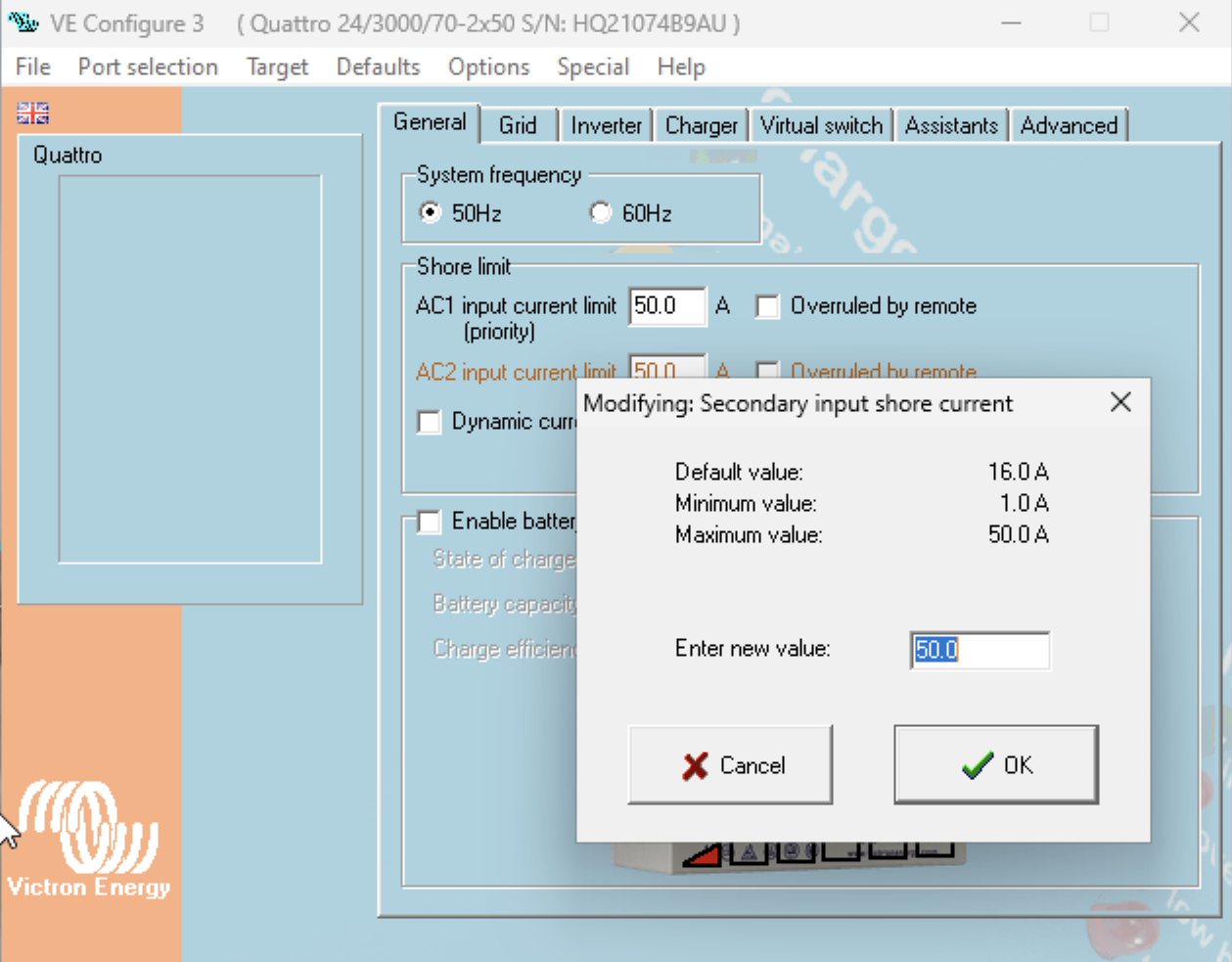
Set the "Shore limit" on the connected AC input to the maximum allowed value.
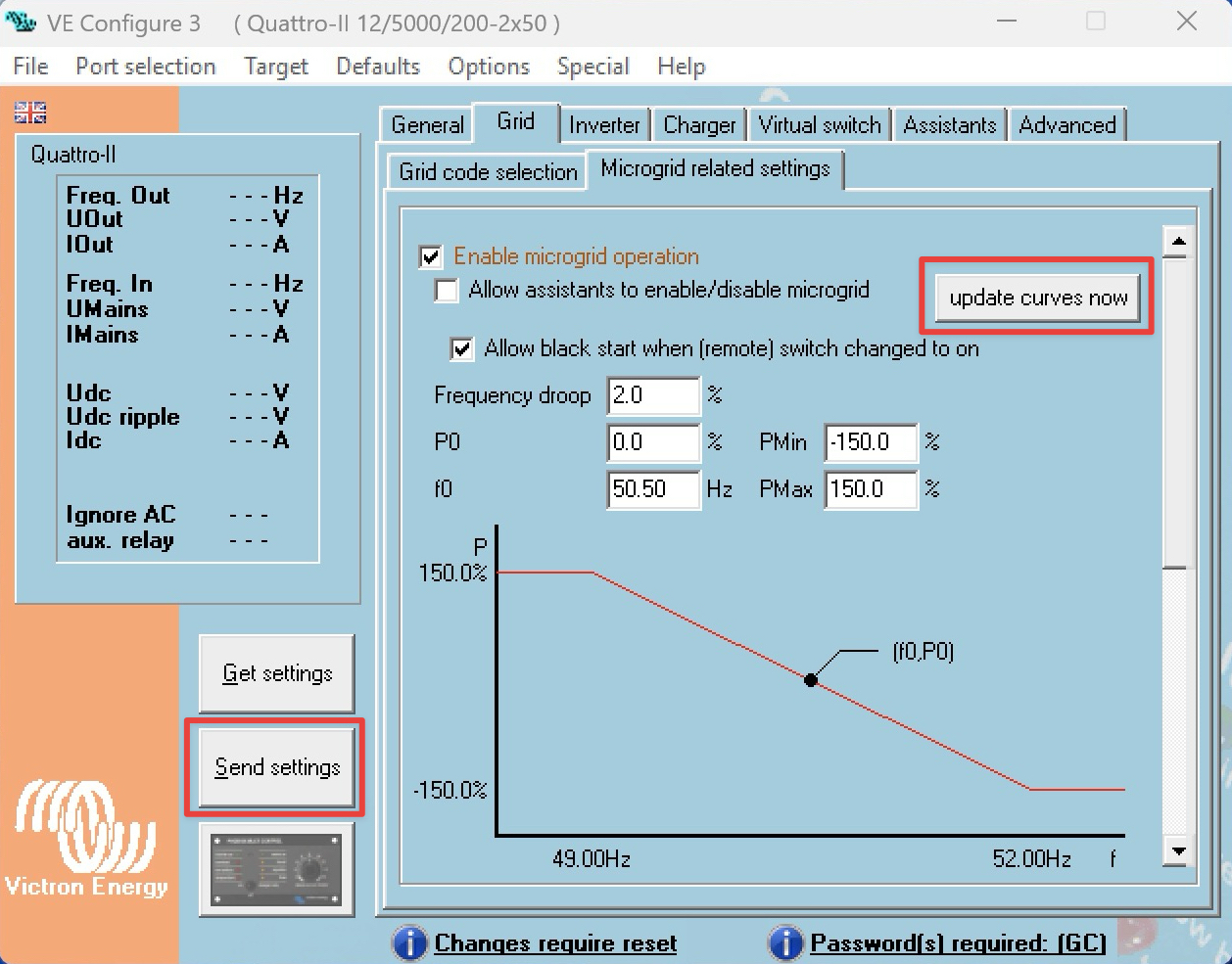
Navigate to the "Grid" tab.
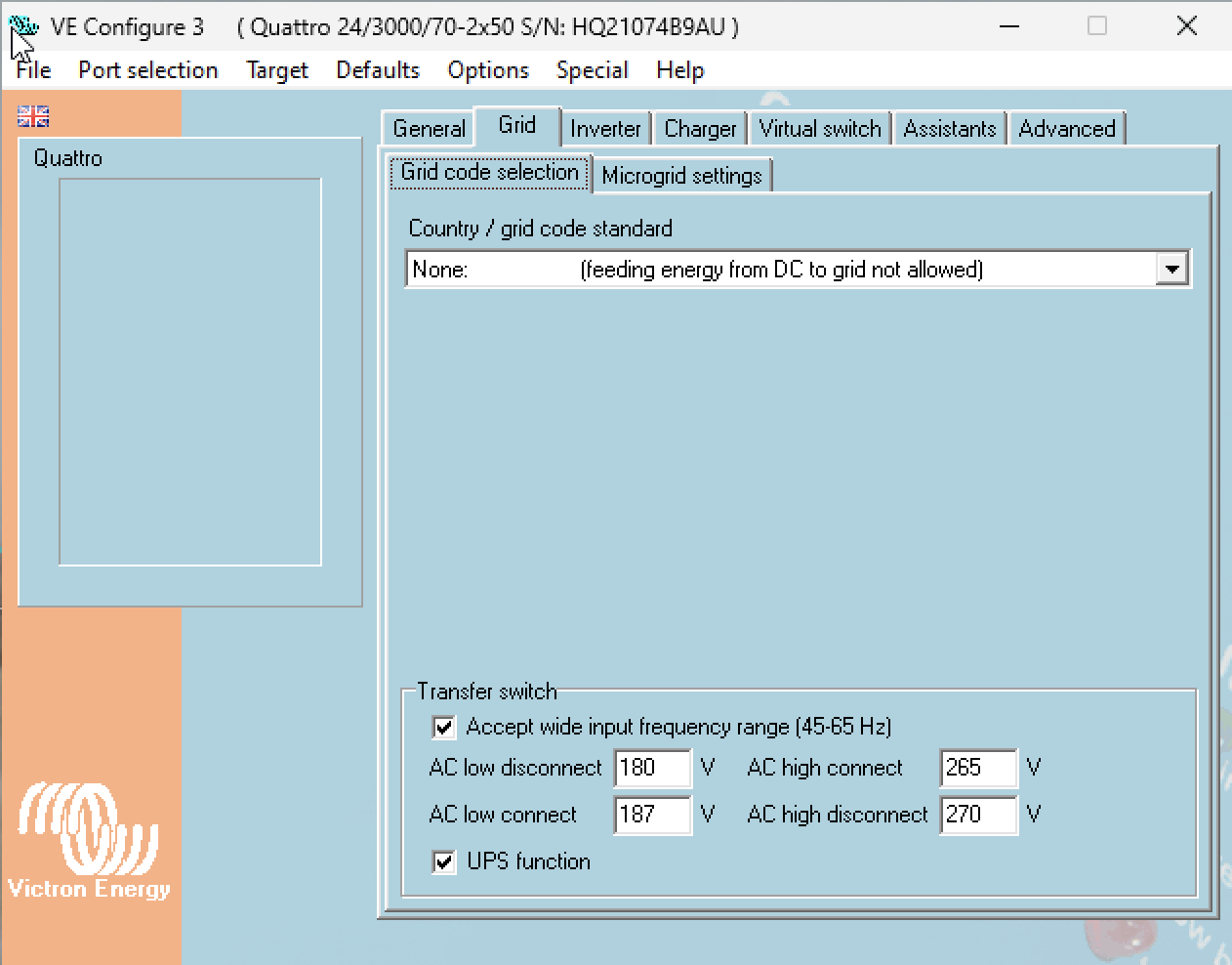
In "Grid code selection" sub-tab, set the grid code to "None".
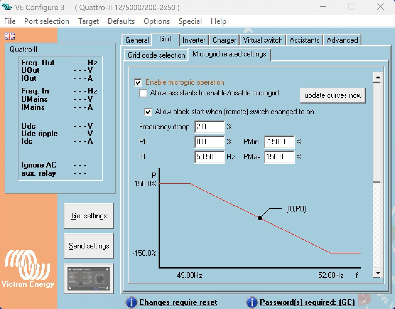
In "Microgrid settings" sub-tab, enable the "Enable Microgrid operation" checkbox.
Note
Victron grid code password is required to enable the "Enable microgrid operation". Contact your Victron dealer for the necessary training to obtain this password.
If desired, also enable the "Allow this system to initiate a black start" checkbox (see notes below).
Navigate to the "Charger" tab
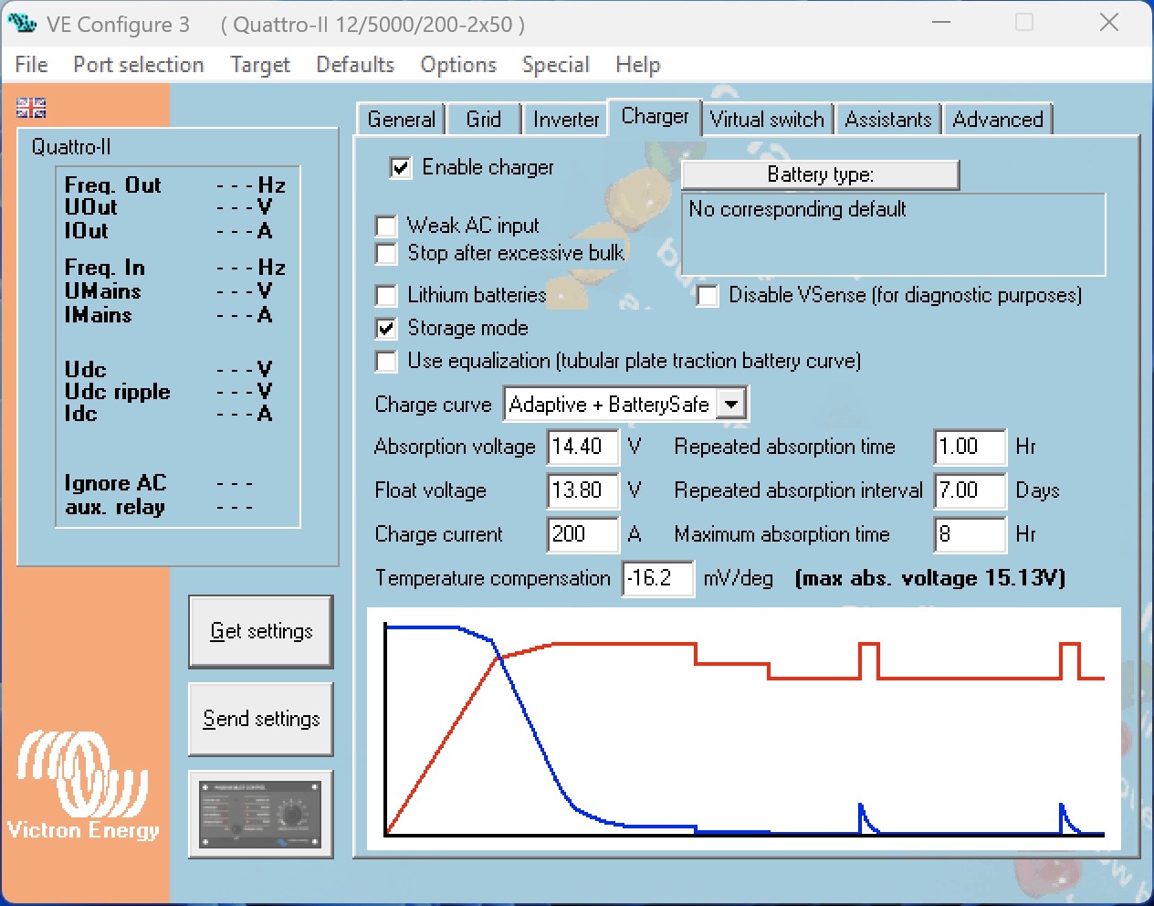
Make sure that "Enable charger" is enabled
Configure "Charge current" to the maximum allowed value.
Configure all other battery charging parameters as required.
Note
The Microgrid feature is designed exclusively for off-grid applications and therefore does not provide support for Grid codes. However as AC-input behaviour is modified, a grid code password is required from your Victron dealer.
Explanation of the Microgrid settings:
With "Enable Microgrid operation" disabled, the inverter/charger operates according to the standard firmware behaviour.
With “Enable Microgrid operation” enabled, the inverter/charger is configured for Hybrid Droop mode, enabling participation in load sharing on the Microgrid AC bus.
The “Allow assistants to enable/disable microgrid” setting is intended for a feature that will be introduced in a future release.
With “Allow black start when (remote) switch changed to on” disabled, the unit will not energize the AC bus on its own. It will wait for another Power Bank to energize the Microgrid AC bus, then synchronize and connect.
With “Allow black start when (remote) switch changed to on” enabled, the unit is permitted to energize the Microgrid AC bus by generating AC voltage on its configured AC input. This permission remains valid only until the Power Bank has successfully closed the transfer switch and connected to an energized AC bus for the first time — regardless of whether the AC bus was energized by another Power Bank or by this unit itself. Following this, black-start capability must be restored manually (see details below).
Black start behaviour
To prevent repeated and uncontrolled restart attempts, black-start capability is limited as follows:
If a Power Bank has “Allow black start when (remote) switch changed to on” enabled, it may initiate a black start only until it has, for the first time established connected to an energized AC bus (either by joining an already energized bus, or by energizing it itself).
If a shutdown event later occurs (for example due to high AC bus voltage, overload, or other protection conditions), the Power Bank:
Can still synchronize with and join an already active Microgrid AC bus.
Cannot initiate a new black start independently.
To restore black-start capability, the Power Bank must be restarted:
Switching all Inverter/Charger in that Power Bank off and then switching all units on again
On a remote monitoring device, like a GX device, or via VRM: Setting Inverter/Charger Mode to "Inverter-only" or "Off" and then to "On" again
Warning
Even if “Allow black start when (remote) switch changed to on” is disabled, once the inverter/charger has synchronized to an active Microgrid AC bus, it will keep its transfer switch closed and continue supplying voltage to the bus – even if other Power Banks are disconnected.
Black start requirement
At least one Power Bank must have black-start capability available in order to energize and start the Microgrid AC bus. If no unit has active black-start permission (for example after a previous successful start without restart), the Microgrid cannot be initiated until a system restart is performed.
4.4. Hybrid droop parameters
Hybrid Droop control defines how each Victron Power Bank reacts to deviations in frequency and voltage on the Microgrid AC bus. Two independent droop mechanisms are implemented:
P–f Droop (Active power vs. frequency)
Q–U Droop (Reactive power vs. voltage)
Together, they determine how active and reactive power are shared between Power Banks and how the AC bus behaves under load.
Warning
It is strongly recommended to keep Hybrid Droop parameters at their default values. Parameters do not need to be changed under normal operation.
Important
All percentage-based power values refer to the nominal active power of the inverter/charger system, which equals 80 to 90 percent of its VA rating, depending on the device model.
This scaling also applies to relative reactive power parameters.
4.4.1. P–f Droop (Active Power vs. Frequency)
The P–f droop defines how active power output changes as a function of frequency deviation.
Configurable parameters
Frequency droop [%] (default: 2.0)
P0 [%] (default: 0.00)
f0 [Hz] (default: 50.50)
Pmin [%] (default: -150.00)
Pmax [%] (default: 150.00)
Operating principle
The parameter f₀ defines the reference frequency. At this frequency, the inverter delivers the active power defined by P₀.
If the measured bus frequency deviates from f₀:
A decrease in frequency causes the inverter to increase active power output.
An increase in frequency causes the inverter to decrease active power output.
The slope of this relationship is defined by the Frequency droop setting.
In a Microgrid with multiple Power Banks:
Identical droop settings result in proportional active power sharing.
Different droop slopes or offsets (P₀, f₀) shift load distribution and dynamic behavior.
Power limits
Active power contribution is bounded by:
Pmin
Pmax
These limits define the allowed active power range relative to nominal inverter power.
Refer to the following screenshot.

4.4.2. Q–U Droop (Reactive Power vs. Voltage)
The Q–U droop defines how reactive power output changes as a function of voltage deviation.
Configurable parameters
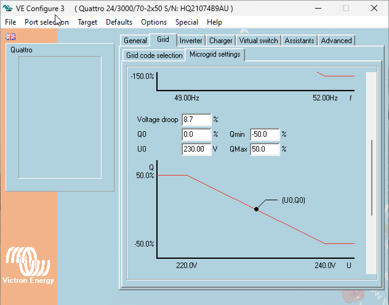
Voltage droop [%] (default: 8.7)
Q0 [%] (default: 0.00)
U0 [V] (default: 230.00)
Qmin [%] (default: -50.0)
Qmax [%] (default: 50.0)
Operating principle
The parameter U₀ defines the reference voltage. At this voltage, the inverter delivers the reactive power defined by Q₀.
If the measured bus voltage deviates from U₀:
A voltage drop results in increased reactive power injection (supporting voltage).
A voltage rise results in reduced or absorbing reactive power.
The Voltage droop parameter defines the slope of the Q–U characteristic.
As with P–f droop:
Identical Q–U settings across all Power Banks result in proportional reactive power sharing.
Modified slopes or offsets influence voltage stiffness and reactive power distribution.
Reactive power limits
Reactive power output is bounded by:
Qmin
Qmax
These limits restrict reactive power contribution relative to nominal inverter power.
Reactive power capability
When the inverter/charger delivers more than 30% of its nominal active power, the minimum achievable power factor (cosφ) is limited to 0.7.
This means that at higher active power levels, the available reactive power is reduced in order to remain within the inverter’s apparent power (VA) capability.
As active power increases, the maximum allowed reactive power decreases accordingly. This limitation is inherent to the inverter’s power stage and must be considered when configuring Q–U droop parameters in Microgrid applications.
Important
Above 30% active power, the minimum power factor is limited to cosφ = 0.7, reducing available reactive power.
Refer to the following screenshot.
4.4.3. Applying Hybrid droop parameters
The Hybrid droop curve parameters are handled using two internal storage mechanisms:
Default parameter storage (non-volatile)
Active runtime storage (volatile)
Understanding the difference between these two is important when modifying droop curves or related settings.
Default Parameter Storage
When pressing “Send settings”, the configured curve data is written to the non-volatile default parameter storage. However, the new curve will not become active immediately. The updated curve will only take effect after a system reset.
This mechanism ensures that permanent configuration changes are applied in a controlled manner.
Active Runtime Storage
When pressing “Update curves now”, the new curve data is sent directly to the Power Bank and written to the active runtime storage. In this case the updated curves become effective immediately and no system reset is required.
This function is intended for temporary adjustments or tuning during commissioning and testing.
The changes remain active until the next reset. After such an event, the system will revert to the curve stored in the non-volatile default parameter storage.
4.4.4. Hybrid droop parameter behaviour reference
The following table summarises all configurable Hybrid Droop parameters and describes the effect of adjusting each one.
P–f droop : Active Power (P) vs Frequency (f)
Parameter | Controls | Effect when changed |
|---|---|---|
Frequency droop [%] | Slope of the P–f characteristic curve | A lower percentage produces a steeper slope, resulting in less frequency deviation under load and a stiffer system response. A higher percentage produces a flatter slope, allowing more frequency deviation but softer load transitions. |
f₀ | Reference frequency | Shifts the operating point along the frequency axis. At this frequency, the inverter delivers the active power defined by P₀. |
P₀ | Active power output at f₀ | Shifts the droop curve vertically. Increasing P₀ biases more active load toward this Power Bank at the reference frequency. Decreasing P₀ reduces its share. |
P_max / P_min | Active power output limits | Clamps the active power contribution regardless of droop calculation. Prevents overload at the upper limit and reverse power flow at the lower limit. Values are expressed as a percentage of nominal inverter power. |
Q–U droop : Reactive Power (Q) vs Voltage (U)
Parameter | Controls | Effect when changed |
|---|---|---|
Voltage droop [%] | Slope of the Q–U characteristic curve | A lower percentage produces a steeper slope, resulting in stiffer voltage regulation and less voltage deviation under reactive load. A higher percentage produces a flatter slope, allowing more voltage deviation. |
U₀ | Reference voltage | Shifts the operating point along the voltage axis. At this voltage, the inverter delivers the reactive power defined by Q₀. |
Q₀ | Reactive power output at U₀ | Shifts the droop curve vertically. Increasing Q₀ causes the Power Bank to inject more reactive power at the reference voltage. Decreasing Q₀ reduces its reactive contribution. |
Q_max / Q_min | Reactive power output limits | Clamps the reactive power contribution regardless of droop calculation. Must be configured within the inverter's apparent power (VA) capability. Values are expressed as a percentage of nominal inverter power. |
Note
All percentage-based power values refer to the nominal active power of the inverter/charger system, which equals 80 to 90 percent of its VA rating (depending on the device model). This scaling also applies to reactive power.
Caution
Above 30% nominal active power, the minimum achievable power factor is limited to cosφ = 0.7. This means available reactive power decreases as active power increases. The Q–U droop limits must be configured with this constraint in mind to avoid requesting reactive power the inverter cannot deliver.
4.5. GX user interface and VRM monitoring
This chapter covers three layers of monitoring and visibility: the GX device local user interface, the VRM portal for individual Power Bank monitoring, and VRM Installation Groups for aggregated Microgrid-wide monitoring.
Each Power Bank in a Microgrid operates independently, and each may have its own GX device connected via VE.Bus to its inverter/charger system. While a GX device is not mandatory, it is strongly recommended. It provides local visibility into the Power Bank's operating state and, when connected to the internet, enables remote monitoring through the Victron Remote Management (VRM) portal.
Venus OS v3.70 or later is required for Microgrid support on the GX device.
Ensure the GX device firmware is updated before commissioning. Refer to the Venus OS version guidance in the [Configuration] chapter, Section 4.5.
4.5.1. GX Device role in the Microgrid
Each GX device monitors a single Power Bank. It connects to the inverter/charger system (MultiPlus, Quattro, MultiPlus-II, or Quattro-II) via VE.Bus and, optionally, to DC charging sources (MPPT solar chargers, battery monitors) via VE.Direct or VE.Can.
In a Microgrid with multiple Power Banks, there is no direct communication between GX devices. Each GX device sees only its own Power Bank. Microgrid-wide visibility is achieved through VRM Installation Groups, described in Section 4.
The GX device provides two categories of information relevant to Microgrid:
Operational data. Real-time readings from the VE.Bus device detail page: AC input voltage and frequency, AC power, DC bus voltage, battery SoC, inverter/charger state, and active AC input.
Microgrid parameters. A dedicated Microgrid submenu displaying the active Hybrid Droop control mode and its configured parameters. These values are read from the inverter/charger firmware settings and displayed for verification.
4.5.2. GX Local User Interface
VE.Bus Device detail page
Navigate to the VE.Bus device detail page from the GX device overview. Select the inverter/charger device from the device list (e.g. "MultiPlus 12/2000/80-32").
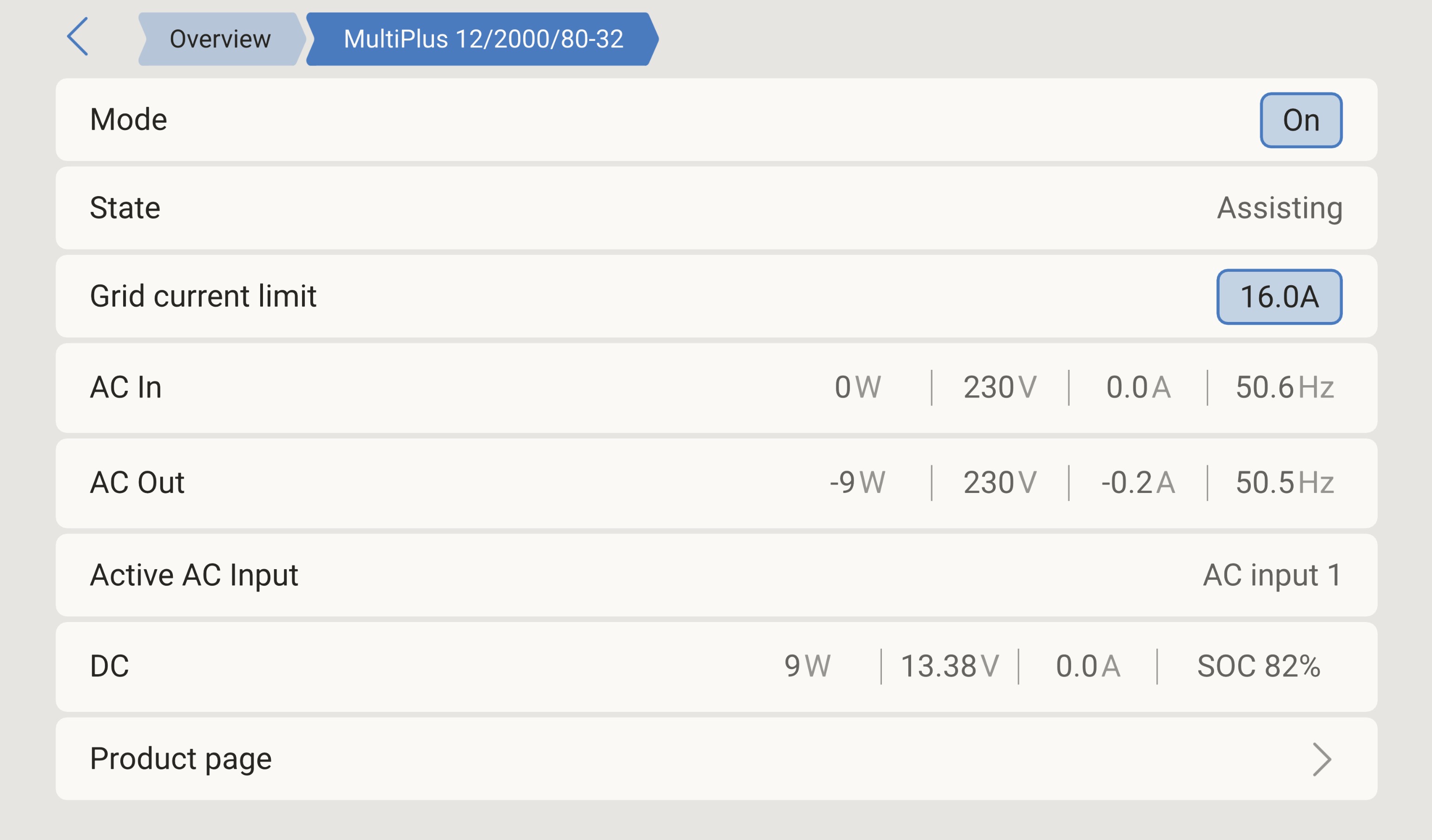 |
The page displays the following fields:
Field | Description | Microgrid relevance |
|---|---|---|
Mode | Current operating mode of the inverter/charger. | Must read On. If set to Charger-only or Inverter-only, the Power Bank cannot participate in Hybrid Droop control. |
State | Operational state (e.g. Assisting, Bulk, Absorption, Float, Inverting). | Assisting indicates the Power Bank is synchronised to the Microgrid AC bus and actively participating. |
Grid current limit | Maximum AC input current setting. | Set to the maximum allowed value per the [Configuration] chapter, Section 4.3. |
AC In | Power (W), voltage (V), current (A), and frequency (Hz) on the AC input, which in a Microgrid is the shared AC bus connected to AC-IN (MultiPlus / MultiPlus-II) or AC-IN-2 (Quattro / Quattro-II). | Frequency is the primary diagnostic value. In a Microgrid operating under Hybrid Droop, AC bus frequency reflects aggregate active power load via the P–f droop relationship. A frequency of f0 (default 50.50 Hz) indicates the Power Bank is at its reference active power (P0). Frequency below f0 indicates the bus is loaded above P0; frequency above f0 indicates it is loaded below P0. |
AC Out | Power (W), voltage (V), current (A), and frequency (Hz) on the AC output terminals. | In a Microgrid, AC-OUT-1 and AC-OUT-2 are not used and must remain disconnected. The AC Out readings may show small residual values but are not operationally relevant. |
Active AC Input | Indicates which AC input terminal is in use. | Confirms the Power Bank is connected to the Microgrid AC bus via the correct input terminal. |
DC | Power (W), voltage (V), current (A), and battery SoC (%). | SoC is critical for operational awareness. The lowest Power Bank SoC in the Microgrid drives load-shedding and shutdown decisions, per the [Operation] chapter. |
The "AC In" frequency reading is the single most important value for Microgrid monitoring at the local GX level.
It serves as a real-time proxy for aggregate percentage load on the Microgrid AC bus. An installer or operator observing bus frequency can immediately assess whether the Microgrid is lightly loaded (frequency near or above f0), moderately loaded (frequency noticeably below f0), or approaching capacity (frequency near the lower droop limit).
Microgrid submenu
Navigate to the Microgrid submenu via Settings → Devices → [VE.Bus device name] → Microgrid.
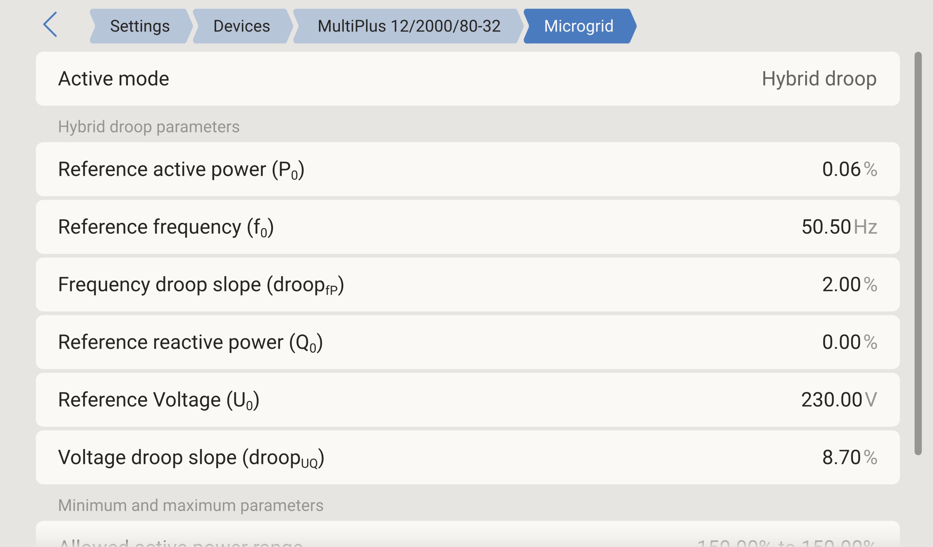 |
This page displays the Hybrid Droop parameters currently configured in the inverter/charger firmware.
These values are read-only on the GX device, they are configured using VEConfigure 3 and VE.Bus System Configurator, per the [Configuration] chapter, Section 4.4.
The Microgrid submenu displays:
Parameter | Value | Description |
|---|---|---|
Active mode | Hybrid Droop | Confirms the inverter/charger is operating in Microgrid Hybrid Droop mode. |
Reference active power (P0) | 0.06% | The active power setpoint at the reference frequency f0. Expressed as a percentage of nominal active power. |
Reference frequency (f0) | 50.50 Hz | The AC bus frequency at which the Power Bank delivers P0. |
Frequency droop slope (droopfP) | 2.00% | The P–f droop slope. Determines how much the Power Bank adjusts its active power output per unit of frequency deviation. |
Reference reactive power (Q0) | 0.00% | The reactive power setpoint at the reference voltage U0. |
Reference Voltage (U0) | 230.00 V | The AC bus voltage at which the Power Bank delivers Q0. |
Voltage droop slope (droopUQ) | 8.70% | The Q–U droop slope. Determines how much the Power Bank adjusts its reactive power output per unit of voltage deviation. |
Below the droop parameters, the submenu displays the allowed operating range:
Parameter | Default value |
|---|---|
Allowed active power range | −150.00% to 150.00% |
Allowed reactive power range | −50.00% to 50.00% |
Use this page to verify that the Hybrid Droop parameters match the intended design.
When commissioning a Microgrid with multiple Power Banks, check that all Power Banks display identical droop parameters, unless intentional asymmetric load sharing has been designed, per the [Configuration] chapter, Section 4.4.
If the Microgrid submenu does not appear in the device menu, verify that the inverter/charger is running firmware with S97 or S98 subversion and that the GX device is running Venus OS v3.70 or later.
4.5.3. VRM portal, individual Power Bank monitoring
Each GX device in the Microgrid registers as a separate installation on the VRM portal (vrm.victronenergy.com). When a GX device is connected to the internet and registered to a VRM account, it continuously uploads system data.
Each Power Bank's VRM installation provides:
Dashboard. Real-time overview of battery SoC, solar yield, AC power flows, and system state.
Advanced page. Detailed historical graphs and data logging for all monitored parameters, including AC input frequency, voltage, power, and battery SoC over time.
Remote Console. Full remote access to the GX device local user interface described in Section 2, including the Microgrid submenu.
Alarm logging and notifications. Historical alarm records and configurable email/push notifications for alarm conditions.
For Microgrid monitoring, the most valuable VRM data points per installation are:
Battery State of Charge trend. Track each Power Bank's SoC over time to identify imbalances between Power Banks. Because there is no automatic SoC balancing between Power Banks, diverging SoC trends may indicate unequal DC charging capacity or load distribution.
AC input frequency trend. The bus frequency logged by each Power Bank provides a historical view of Microgrid loading. Since all Power Banks are on the same AC bus, their frequency readings should be consistent.
Inverter/charger state transitions. State changes (Assisting, Bulk, Absorption, Float) indicate when a Power Bank is contributing to the Microgrid, or disconnected.
Use consistent, descriptive installation names for each Power Bank (e.g. "Site Name PB1", "Site Name PB2") to simplify identification when working with multiple installations.
4.5.4. VRM portal, Microgrid monitoring with Installation groups
When a Microgrid contains multiple Power Banks, each with its own GX device and VRM installation, it's possible to monitor them individually and collectively.
VRM Installation Groups provide a mechanism to view all Power Banks belonging to a single Microgrid in a unified list with aggregated totals.
Creating an Installation Group
Log in to the VRM portal.
Navigate to Teams & Groups in the left sidebar.
Select Installation groups.
Click Create installation group in the upper right.
Enter a descriptive group name that identifies the Microgrid site.
Click Create installation group to confirm.
A VRM account can contain multiple Installation Groups. Only installations to which the account has full access can be added to a group.
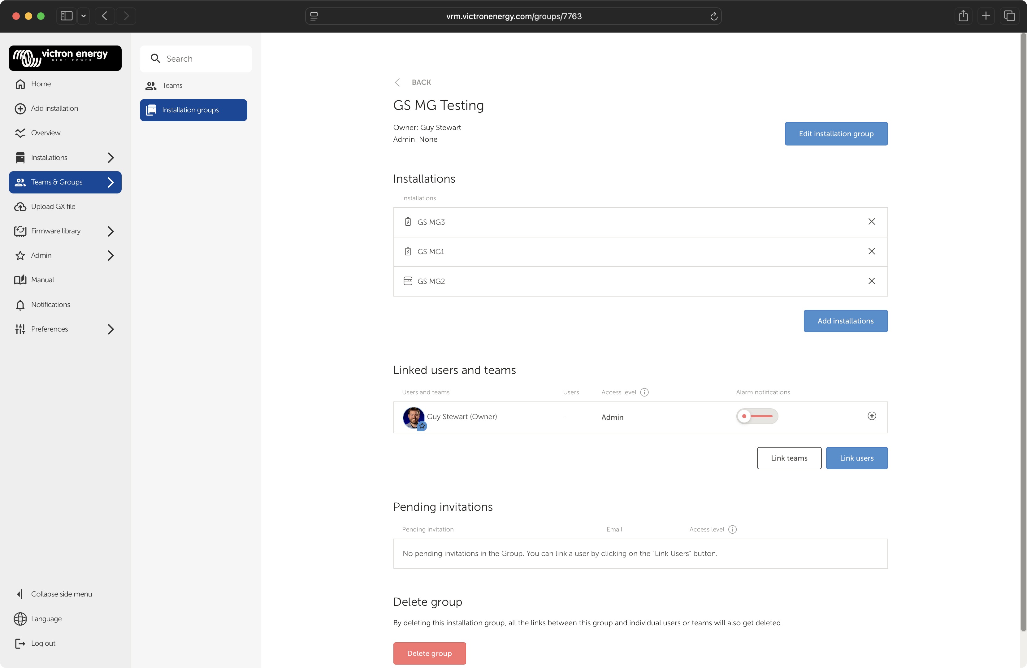
Adding Power Banks to the Group
After creating the group:
Open the group by clicking its name in the Installation groups list.
Click Add installations
Select each GX device installation that belongs to the Microgrid (e.g. "GS MG1", "GS MG2", "GS MG3").
Confirm the selection.
All Power Banks in the Microgrid should be added to the same group. The group detail page displays the list of included installations and allows adding or removing installations at any time.
Linking Users and Teams
The Installation group detail page also allows access management.
Under Linked users and teams, link additional VRM users or teams who need visibility into the Microgrid. Each linked user or team is assigned an access level (e.g. Admin) and can optionally receive alarm notifications.
Use this feature to grant monitoring access to site operators, maintenance personnel, or remote support teams without sharing credentials for individual installations.
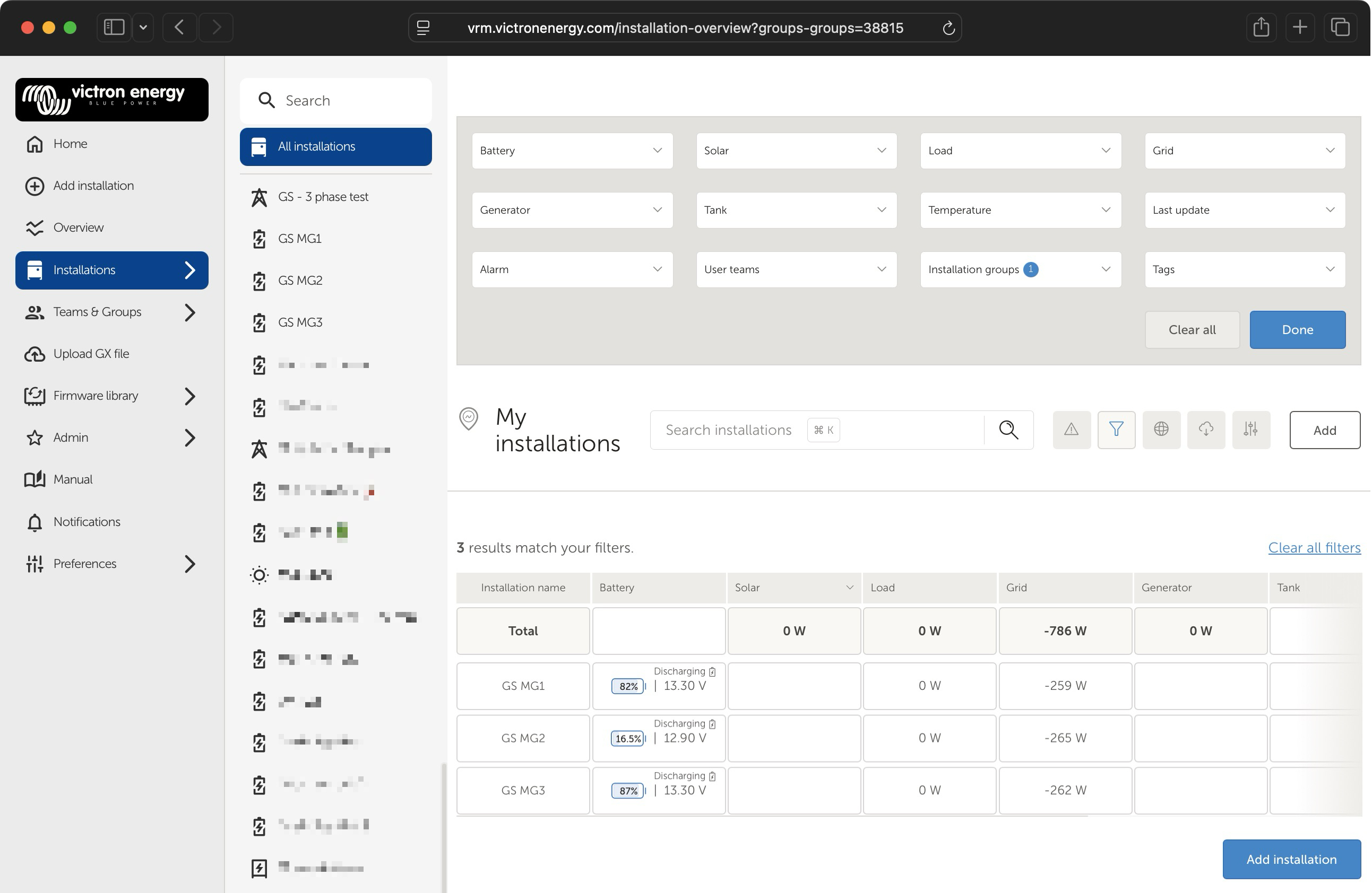
Viewing the Microgrid as a group
Once the Installation Group is created and populated:
Navigate to Installations in the left sidebar.
Select All Installations.
Open the filter panel
Set the Installation groups filter to the Microgrid group name.
Click Done to apply the filter.
The filter set is stored in the URL, so if you want to create a shortcut to this filtered view, create a bookmark.
The Installations list now shows only the Power Banks belonging to the selected Microgrid. The view includes:
A Total row at the top, displaying the sum of Solar, Load, Grid, and Generator power across all Power Banks in the group. This provides the aggregated Microgrid-wide power flow at a glance.
Note: In a Microgrid configuration, the inverter operates by pushing power via the AC input. This is reflected as a 'grid export' in the Total row and other elements of the UI. Its normal for the column labeled Load to show zero.
Individual Power Bank rows below the Total, each showing: installation name, battery SoC and voltage, solar yield, load power, and last update timestamp.
This is the primary Microgrid-wide monitoring view. Use it to:
Compare SoC across Power Banks. Significant SoC divergence between Power Banks (e.g. one at 82% while another is at 17%) indicates an imbalance that requires investigation, typically unequal DC charging capacity, different battery sizes, or differing load history.
Verify all Power Banks are online. The "Last update" column confirms each GX device is communicating. A stale timestamp may indicate a GX device has lost internet connectivity or the Power Bank has shut down.
Monitor aggregate load. The Total row provides a quick check on whether the Microgrid is operating within its aggregate continuous rating (P_total = sum of 80% × VA per Power Bank).
Check for alarms. The Alarm column shows whether any Power Bank has active alarms. A count of "0/N" (where N is the number of Power Banks) indicates no active alarms.
Using filters for targeted monitoring
The VRM Installations view provides additional filter dropdowns beyond Installation groups: Battery, Solar, Load, Grid, Generator, Tank, Temperature, Last update, Alarm, User teams, and Tags.
These filters can be combined with the group filter to further narrow the view, for example, filtering for Power Banks with active alarms, or sorting by battery SoC to identify the lowest Power Bank.
4.6. Venus OS version
If a GX device is used, it should be updated to Venus OS version 3.70 or later.