2. Functionality
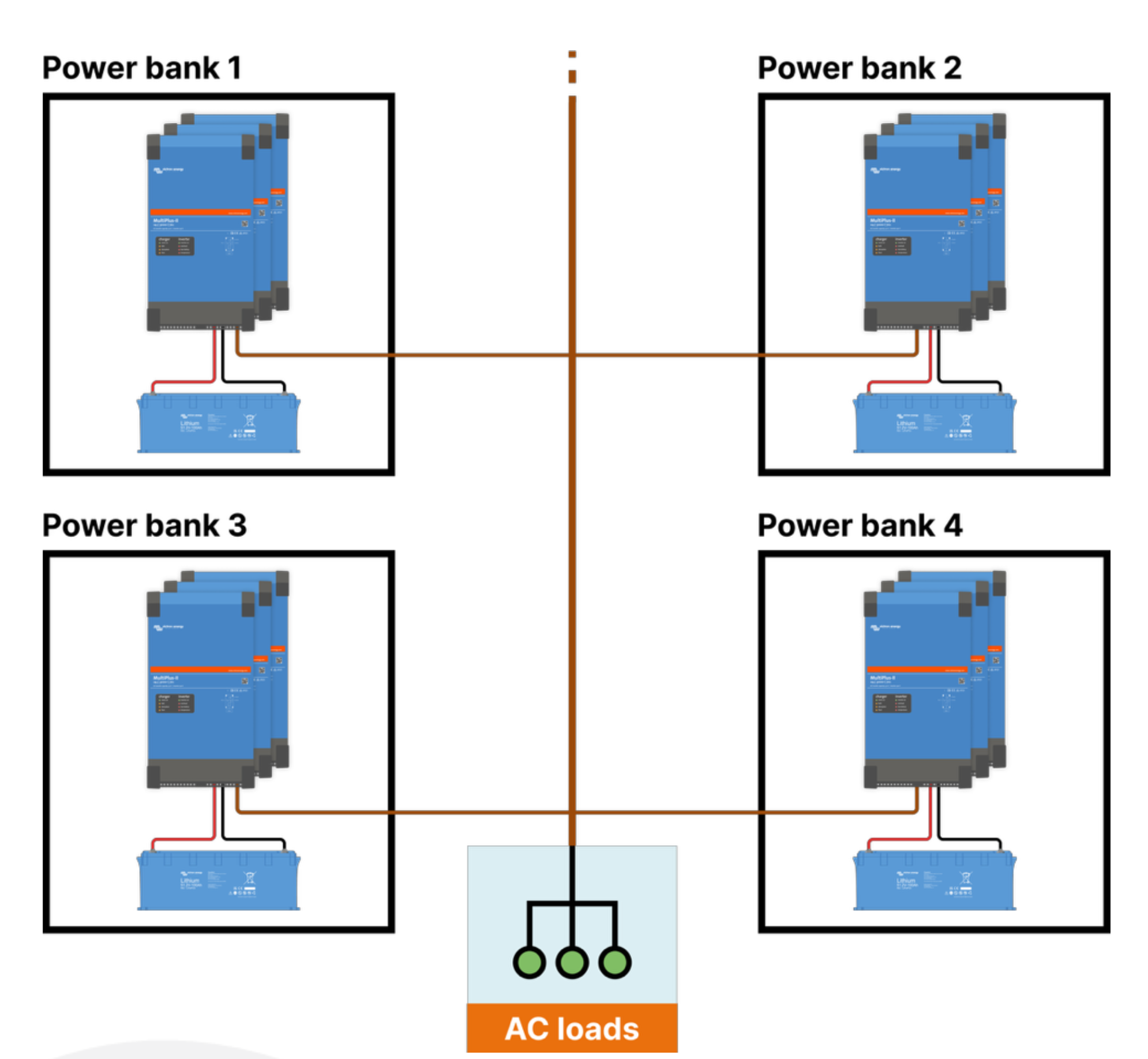
The Microgrid functionality enables multiple independent inverter/charger systems (Victron Power Banks) to operate together on a shared AC bus in off-grid applications.
Each Power Bank consists of a MultiPlus, Quattro, MultiPlus-II, or Quattro-II system connected to its own battery system. Instead of forming one large VE.Bus system with a shared DC bus, several such systems are interconnected only via the AC side.
All participating Power Banks operate in Hybrid Droop mode and jointly establish and regulate the AC bus. Load sharing between the units is achieved through controlled frequency and voltage deviation on the AC bus.
When system load changes:
All Power Banks automatically adjust their output.
Load is shared proportionally (with identical droop settings).
No external Energy Management System (EMS) is required.
The system operates exclusively off-grid. The AC bus is fully formed and stabilized by the participating Power Banks.
Caution
Coupling with other AC sources (AC PV Inverters, AC gensets, etc.) is not supported.
2.1. Comparison to standard operation
In a standard VE.Bus system, AC input is used to connect to an upstream AC source (grid or generator), while loads are supplied via AC output. The internal or external transfer switch manages the transition between inverter operation and passthrough (or PowerAssist) operation.
In a Microgrid application using Hybrid Droop mode, this behaviour changes fundamentally:
The AC input is used to connect the Power Bank to the shared Microgrid AC bus.
The AC input is therefore permanently connected to a live AC system formed collectively by all participating Power Banks.
AC outputs must not be connected to load in Microgrid applications.
Unlike a standard application, the AC input is not considered an upstream supply but the interconnection point to the common off-grid bus. The internal or external transfer switch is not used to switch between external AC input and inverter operation; instead, the inverter continuously participates in forming and stabilizing the AC bus via Hybrid Droop control.
This results in a different electrical topology compared to conventional VE.Bus installations and must be considered during system design and wiring.
Warning
In this application, AC input is live whenever a Power Bank assists the Microgrid. Therefore, always treat AC input as a live terminal.
If removable connectors are used, touch-safe connectors are required. Powerlock connectors are one commonly used solution that can meet this requirement.
2.2. Limitations and constraints
The Victron Microgrid functionality is designed as a decentralized, droop-controlled, off-grid architecture focused on stable and proportional load sharing between multiple Victron Power Banks.
The system intentionally follows a simplified and robust design philosophy. While this enables modularity, scalability, and resilience, certain features commonly found in other microgrid architectures are not part of the current implementation.
The following constraints apply.
2.2.1. Off-Grid operation only
Hybrid droop operation is intended exclusively for islanded systems. The Microgrid AC bus is fully formed and stabilized by the participating Power Banks and must not be connected to a public utility grid. Grid-connected operation in Microgrid mode is not supported.
This makes the system suitable for stand-alone power systems, remote installations, and containerised distributed generation, but not for grid-interactive hybrid plants.
2.2.2. Maximum system size
Microgrid applications are supported with a total inverter output of up to 400 kW, defined as the sum of the inverter output power across all Power Banks.
2.2.3. Decentralized control philosophy
The Microgrid operates without centralized dispatch control. Load sharing is achieved exclusively through droop control, using frequency and voltage as the coordination mechanism between Power Banks.
External Energy Management Systems (EMS) for distributing active power setpoints to individual Power Banks are not supported; And there is no centralised economic dispatch or optimisation layer. The system is intentionally designed to function without fast communication links between units, increasing robustness while limiting advanced supervisory control strategies.
2.2.4. AC bus usage
The Microgrid AC bus is intended for interconnecting Victron Power Banks and supplying loads. It is not designed as a general-purpose paralleling bus for additional AC generation sources.
AC-coupled PV inverters, external grid-forming inverter systems, or directly paralleled generators are not supported on the Microgrid AC bus. Battery charging must be provided individually per Power Bank via DC-coupled sources or dedicated AC chargers supplied from an external source.
This architectural decision ensures controlled droop interaction and predictable system dynamics.
2.2.5. Independent battery systems
Each Power Bank operates with its own battery system and manages it independently. There is no shared DC bus and no automatic state-of-charge balancing between Power Banks.
Energy distribution between units is therefore governed solely by droop characteristics and system design. Coordinated charging strategies must be considered during project planning.
2.2.6. Black-Start behaviour
Black-start capability is intentionally limited to prevent uncontrolled restart loops. Once a Power Bank has successfully established or joined an energized Microgrid, its ability to initiate a new black start is disabled until the inverter/charger(s) was restarted.
2.2.7. System positioning
The Victron Microgrid architecture extends the well-known VE.Bus system concept into a modular AC-coupled environment. It enables scaling beyond the limits of a single inverter/charger system while maintaining a decentralized and inherently stable operating principle.
It is not intended to replace centralized microgrid controllers with advanced dispatch, grid-forming hierarchies, or complex generator coordination. Instead, it provides a robust and scalable foundation for off-grid AC-coupled power systems based on proven droop control principles.
2.3. Topology
| ||