11. Appendix
11.1. LED indications, warnings, alarm and error codes
LEDs
The Lynx Smart BMS is equipped with two LEDs, the Bluetooth LED and the Status LED. These LEDs will indicate the operation mode and the fault mode in case there is a fault.
Bluetooth LED | Description |
|---|---|
Off | No system power or Bluetooth disabled in VictronConnect app. Bluetooth can be disabled in both, VictronConnect and a GX device, but only enabled from a GX device. |
Blue on | A Bluetooth device is connected to the Lynx Smart BMS |
Blue flashing | Bluetooth is active but no device is connected |
Blue flashing at 3 seconds interval | The Lynx Smart BMS is in OFF mode but is still accessible over Bluetooth |
Status LED | Description |
|---|---|
Off | The Lynx Smart BMS is in OFF mode |
Orange on | Initializing or shutdown |
Orange blinking | Delayed shutdown due to cooling down the pre-charge circuit |
Green on | Running, the contactor is closed |
Green blinking | Pre-charging |
Green flashing at 3 seconds interval | The Lynx Smart BMS is in Standby mode |
Green and red alternating | System in bootloader mode (updating firmware) |
Red flashing 1 time every 4 seconds | Warning, see VictronConnect for more information |
Red flashing 2 times every 4 seconds | Battery communication error, check battery BMS cables |
Red flashing 3 times every 4 seconds | High/low cell voltage or high/low temperature detected |
Red flashing 4 times every 4 seconds | High BMS temperature detected |
Red flashing 5 times every 4 seconds | Pre-charge time out |
Red flashing 6 times every 4 seconds | Pre-charge high current |
Red flashing 7 times every 4 seconds | Probably wrong system voltage |
Red flashing 8 times every 4 seconds | Contactor current too high |
Red flashing 9 times every 4 seconds | Initialization error |
Red flashing 10 times every 4 seconds | Safety contactor failure |
Red flashing 12 times every 4 seconds | Internal supply error |
Red flashing 14 times every 4 seconds | Battery voltage not allowed |
Warning, alarm and error codes
Warning, alarm and error codes are also reported via the VictronConnect app or a connected GX device and VRM.
A warning indicates a problem that, if not corrected, will result in a system shutdown, while an alarm indicates the reason for the system shutdown.
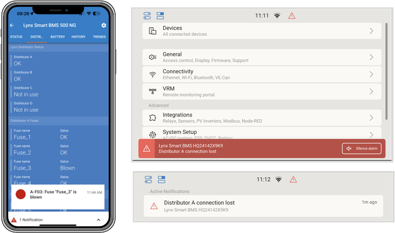 |
Lynx Smart BMS alarms on the VictronConnect App and a GX device
The following tables list all warning, alarm and error codes:
Warnings: Warnings indicate an issue that when unresolved will lead to a system shutdown
VictronConnect warning code | Message | Instructions / remarks |
|---|---|---|
W-B01 | Low cell voltage | Charge the battery or reduce the load to prevent an imminent system shutdown. |
W-B02 | High current | Reduce the current to prevent an imminent system shutdown. Do this by reducing the load or by turning loads off. |
W-B03 | High BMS temperature | Check the ambient temperature and check if the BMS fans are running. If the fans are running, reduce the ambient temperature. If the fans are not running, contact your Victron dealer. |
W-B04 | Warning bad contactor | Reduce the current to prevent an imminent system shutdown. Do this by reducing the load or by turning loads off. Contact your Victron dealer. |
W-B06 | Load will disconnect | The loads will be turned off in 30 seconds if fault is not resolved. For example low battery voltage. This warning is always in combined the reason why the load will disconnect. The loads are turned off via the ATD contact and/or via the GX device. |
W-B07 | Low SoC | Charge battery or reduce load to prevent imminent system shutdown. |
W-B10 | VE.CAN disconnected | Check communication cabling. |
W-D01 | Communication with distributor A lost | Check the cable between BMS and Distributor. |
W-D02 | Communication with distributor B lost | Check the cable between BMS and Distributor. |
W-D03 | Communication with distributor C lost | Check the cable between BMS and Distributor. |
W-D04 | Communication with distributor D lost | Check the cable between BMS and Distributor. |
W-D05 | Communication with distributor E lost | Check the cable between BMS and Distributor. |
W-D06 | Communication with distributor F lost | Check the cable between BMS and Distributor. |
W-D07 | Communication with distributor G lost | Check the cable between BMS and Distributor. |
W-D08 | Communication with distributor H lost | Check the cable between BMS and Distributor. |
Alarms: Alarms indicate the reason why the system is shutdown.
VictronConnect alarm code | Message | Instructions / remarks |
|---|---|---|
A-B01 | Low cell voltage | Charge battery. The system will turn the loads back on when the battery is sufficiently charged. |
A-B02 | High current | Reduce charging current or turn off some loads. The system will try to re-enable chargers or loads in 5 minutes. |
A-B06 | Load disconnected | The loads have been turned off via the ATD contact and/or via the GX device. Resolve this alarm by charging the battery. If not resolved, eventually the contactor will open and the DC system will be disconnected. |
A-B07 | Low SoC | Charge battery. The system will turn the loads back on when the battery is sufficiently charged. |
Error codes
VictronConnect error code | Message | Instructions / remarks |
|---|---|---|
E-B01 | Battery init failure | Check that all batteries are properly connected. |
E-B02 | No battery found | Verify that the BMS cable loop is closed. |
E-B05 | Invalid number of batteries | Check that all batteries are properly connected. |
E-B09 | Battery voltage not allowed | The battery voltage is too high or too low. Check the battery voltage and check the battery settings in the VictronConnect app. This error occurs when the battery voltage is outside all system voltage ranges (9V > Vbat > 60V) |
E-B11 | Hardware error | Contact your Victron dealer. |
E-B25 | Pre-charge error | The load resistance is too low to pre-charge the loads. Disconnect or reduce some DC loads. |
E-B26 | Contactor error | Contact your Victron dealer. |
E-B32 | BMS cable error | Check the battery M8 cabling. |
E-B34 | Wrong system voltage | Check battery voltage settings in the VictronConnect app. |
E-B35 | Pre-charge timeout | The load capacity is too high to pre-charge. Disconnect some DC loads. |
E-B36 | ATC/ATD failure | Check ATC/ATD wiring and make sure that all loads and chargers are controlled by ATC or ATD. |
E-B116 | Calibration data lost | Contact your Victron dealer. |
E-B119 | Settings data lost | Settings data is corrupt. Go to the settings page and reset to defaults. |
Alarm codes Lynx Distributor related
VictronConnect alarm code | Message | Instruction / remarks |
|---|---|---|
A-F01 | Fuse "Fuse_1" is blown | Check your system and replace fuse. |
A-F02 | Fuse "Fuse_2" is blown | |
A-F03 | Fuse "Fuse_3" is blown | |
A-F04 | Fuse "Fuse_4" is blown | |
A-F05 | Fuse "Fuse_5" is blown | |
A-F06 | Fuse "Fuse_6" is blown | |
A-F07 | Fuse "Fuse_7" is blown | |
A-F08 | Fuse "Fuse_8" is blown | |
A-F09 | Fuse "Fuse_9" is blown | |
A-F10 | Fuse "Fuse_10" is blown | |
A-F11 | Fuse "Fuse_11" is blown | |
A-F12 | Fuse "Fuse_12" is blown | |
A-F13 | Fuse "Fuse_13" is blown | |
A-F14 | Fuse "Fuse_14" is blown | |
A-F15 | Fuse "Fuse_15" is blown | |
A-F16 | Fuse "Fuse_16" is blown | |
A-F17 | Fuse "Fuse_17" is blown | |
A-F18 | Fuse "Fuse_18" is blown | |
A-F19 | Fuse "Fuse_19" is blown | |
A-F20 | Fuse "Fuse_20" is blown | |
A-F21 | Fuse "Fuse_21" is blown | |
A-F22 | Fuse "Fuse_22" is blown | |
A-F23 | Fuse "Fuse_23" is blown | |
A-F24 | Fuse "Fuse_24" is blown | |
A-F25 | Fuse "Fuse_25" is blown | |
A-F26 | Fuse "Fuse_26" is blown | |
A-F27 | Fuse "Fuse_27" is blown | |
A-F28 | Fuse "Fuse_28" is blown | |
A-F29 | Fuse "Fuse_29" is blown | |
A-F30 | Fuse "Fuse_30" is blown | |
A-F31 | Fuse "Fuse_31" is blown | |
A-F32 | Fuse "Fuse_32" is blown | |
* If the fuse name is not set, the default name is used. If it is set, the name configured in VictronConnect for the Lynx Distributor is used. | ||
11.2. Supported NMEA 2000 PGNs
Description | PGN |
|---|---|
Product Information | 126996 |
DC detailed Status | 127506 |
DC/Battery Status | 127508 |
Switch Bank Status
| 127501 |
Class and function:
N2K device class: Electrical generation
N2K device function: Battery
For more information see the NMEA2000 & MFD integration guide.
11.3. List of battery monitor settings
Description | default value | adjustable | fixed | automatic |
|---|---|---|---|---|
Battery capacity | 200Ah | Yes | No | No |
Charged voltage | 14.0V/28.0V/56.0V* | Yes | No | No |
Tail current | 4% | Yes | No | No |
Zero current calibration | --- | No | No | Yes (at power up) |
Peukert exponent | 1.05 | No | Yes | No |
Charge efficiency factor | 99% | No | Yes | No |
Current threshold | 0.05A | No | Yes | No |
Low SoC warning level | 15% | Yes | No | No |
Discharge floor | 10% | Yes | No | No |
Delta T | 1 | No | Yes | No |
SoC Cycle end | 90% | No | Yes | No |
SoC Cycle | 65% | No | Yes | No |
SoC full discharge | 5% | No | Yes | No |
* for a 12V/24V/48V system
11.4. Multiconnector pin-out and overview
Pin | Name | Type | Function |
|---|---|---|---|
1 | AUX voltage output + | System voltage positive | The positive connection to power auxiliary devices, like a GX device. |
2 | AUX voltage output - | System voltage negative | The negative (ground) connection to power auxiliary devices, like a GX device. |
3 | Allow to charge | Potential free contact | Turns chargers on or off via a wired signal. Pin 3 can be used as the signal input for pin 4 and wired e. g. from AUX + or AUX -. See system examples for correct wiring. When charging is allowed, the contacts are closed and when not allowed, the contacts are open. |
4 | |||
5 | Allow to discharge | Potential free contact | Turns loads on or off via a wired signal. Pin 5 can be used as the signal input for pin 6 and wired, e. g. from AUX + or AUX -. See system examples for correct wiring. When discharging is allowed, the contacts are closed and when not allowed, the contacts are open. |
6 | |||
7 | Programmable relay NC | Potential free contact | The programmable relay is used to either control an alternator or as an alarm relay. For details, see chapter Programmable relay wiring. |
8 | Programmable relay COM | Potential free contact | |
9 | Programmable relay NO | Potential free contact | |
10 | Remote on/off H | Pull-up resistor | To remotely turn the Lynx Smart BMS on or off. For full functionality, see chapter Wiring the Remote on/off. |
11 | Remote on/off L | Pull-down resistor | |
12 | TEMP + | Sensor | Positive Input for external temperature sensor (1000A only, not supported, future use) |
13 | TEMP - | Sensor | Negative Input for external temperature sensor (1000A only, not supported, future use) |
11.5. Lynx Smart BMS related menu structure of the GX device
This is an overview of the Lynx Smart BMS related menu structure of the GX device. To see all menu items shown here, Venus OS v2.90 or later is required.
Menu item | Default value / unit | Description and / or possible values |
|---|---|---|
Lynx Smart BMS | Shows SoC, voltage and current in the device list | |
Switch | On | Soft switch to manually switch the Lynx Smart BMS to Standby or On mode |
State | Running | Possible states: Initialising, Pre-charging, Running, Shutdown, Standby |
Error | #0 - No error | Error state |
Battery | Voltage, current, power | Shows current battery monitor data |
State of charge | % | State of charge in percent |
Consumed AmpHours | Ah | Displays the consumed AH since the battery was last fully charged |
Time-to-go | Days / Hours | Displays the estimated time, based on the current load and discharge floor setting |
Alarms | ||
High internal temperature | Ok | |
Low cell voltage | Ok | |
Low SoC | Ok | |
History | ||
Deepest discharge | Ah | The deepest discharge since last history reset |
Total charge cycles | 0 | Number of charge cycles since last history reset |
Number of full discharges | 0 | A full discharge is accounted for after SoC falls below 5% |
Cumulative Ah drawn | Ah | Cumulative Ah drawn since last history reset |
Minimum voltage | V | Minimum voltage since last history reset |
Maximum voltage | V | Maximum voltage since last history reset |
Synchronisation count | 0 | Cumulative number of battery monitor synchronisations |
Discharged energy | kWh | Cumulative number of discharged energy since last history reset |
Charged energy | kWh | Cumulative number of charged energy since last history reset |
Clear history | Press to clear | Clears all history data |
Diagsnostics | ||
Diagnostics | Shows last known errors | |
Fuses | ||
Distributor A | Ok | Possible states: Ok, Fuse blown |
Fuse 1..4 | Ok | Possible states: Ok, Not used, Blown |
Distributor B | Ok | Possible states: Ok, Fuse blown |
Fuses 1..4 | Ok | Possible states: Ok, Not used, Blown |
IO | ||
System switch | Enabled | Status of the system switch |
Allow to charge | Yes | Status of the ATC signal |
Allow to discharge | Yes | Status of the ATD signal |
Device | Device related parameters and custom name setting | |
Parameters | ||
Charge Voltage Limit (CVL) | V | Shows the voltage target send to DVCC compatible chargers (for a 12V battery: 13.50V or 14.20V) |
Charge Current Limit (CCL) | A | Maximum allowed charge current limit send to DVCC compatible chargers |
Discharge Current Limit (DCL) | A | Maximum allowed discharge current limit |
11.6. Reversed power distribution
WARNING: Electrical shock and fire hazard
Disable and remove all voltage sources before opening the enclosure or performing any service operations. Use a voltmeter to ensure that there is no residual voltage from internal capacitors, batteries or the like. Failure to observe this instruction may result in burns or fire.
11.6.1. Introduction
This guide describes how to configure the Lynx Smart BMS and Lynx Smart BMS NG for reversed power distribution.
By default, power flows from left to right: DC power sources connect to the left-hand side, and DC loads to the right. This guide is intended for cases where this arrangement needs to be reversed. It applies to all models and hardware revisions of the Lynx Smart BMS.
11.6.2. Models and variants
There are currently two models and two variants of the Lynx Smart BMS.
The models differ by current rating:
500 A version with one power contactor
1000 A version with two power contactors
The variants are distinguished by enclosure marking:
NG (New Generation)
Non-NG (original design)
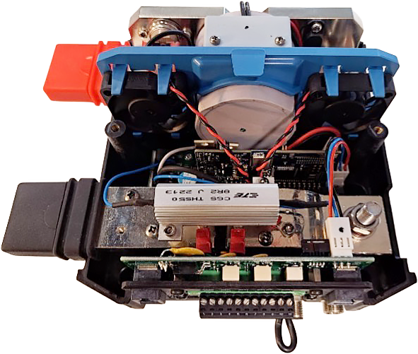 | 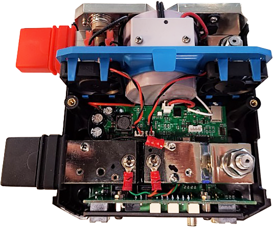 |
11.6.3. Technical background
The primary function of the Lynx Smart BMS is to monitor system and battery voltages, as well as the currents flowing through the device, thereby protecting the battery from under- and overcharging.
Before closing the main power contactor, the BMS performs a short-circuit check on the load side by pre-charging any connected loads. It also monitors the current through the busbar’s shunt to prevent over-current situations that could damage cables or the battery.
Reversing the power distribution requires specific configuration changes, as the load and source connections - and the current flow through the shunt - are reversed. The current shunt is a low-ohmic resistor, precisely factory-calibrated. User modifications to the shunt are not permitted, as even minor changes can introduce contact resistance and invalidate the calibration.
To compensate for the reversed current flow, a dedicated software setting is available. This must be configured via Bluetooth using the VictronConnect app, available from the Victron Energy website.
Caution
Without these modifications, the Lynx Smart BMS will not function as intended.
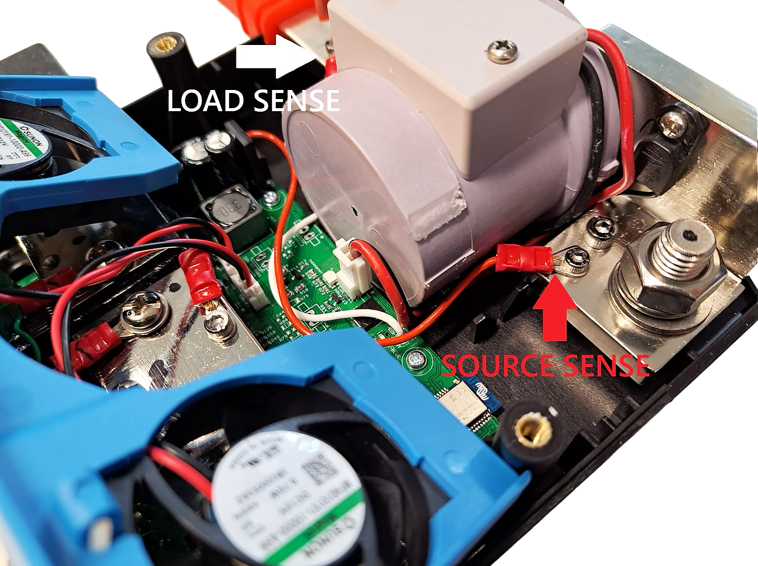
11.6.4. Wiring adjustment procedure
This procedure involves relocating the voltage sense wires on either side of the power contactor:
Voltage sense wires involved:
Red wire = Source voltage
White wire = Load voltage
Steps
Access the wiring area
Remove the fan bracket from its holder and set it aside
Do not disconnect the fan cables; the connector has limited mating cycles.
Swap the wires
Move the white wire to the left side
Note
For the Lynx BMS 1000A: On units with serial numbers before HQ2530, the white wire may be too short and will need to be extended.
Move the red wire to the right side
Use a 2.5 mm Allen key to loosen the screws, reposition the wires, and re-tighten them.
Secure the wiring
Ensure screws are snug, but do not overtighten.
Route the wires neatly along the bottom corner of the power contactor to avoid obstructing the fan bracket.
Refit the fan bracket.
Check clearance
Ensure the now-crossed wires do not block the internal light pipes.
Close the unit
Refit the enclosure cover and tighten all screws before applying power.
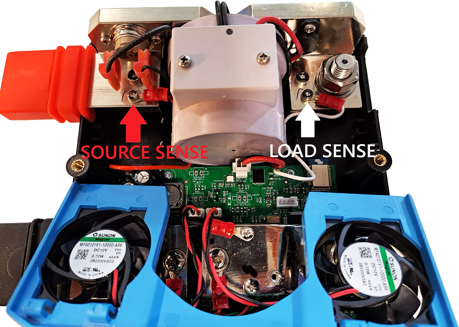 Source and load voltage sense |
Swapped wires for reversed power distribution |
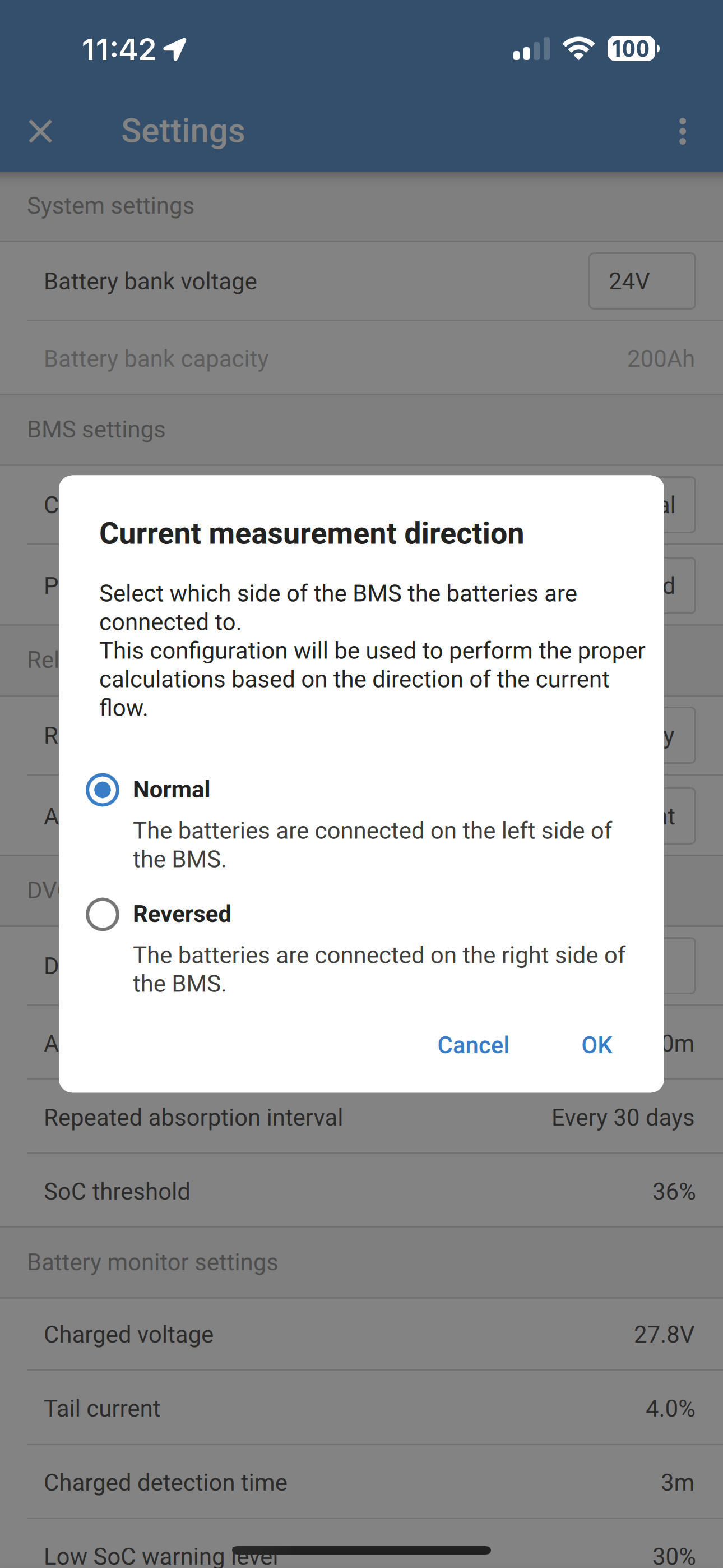
11.6.5. Configuring the reversed current setting
Follow these steps after completing the voltage sense wire swap:
CautionWithout applying both the wiring and software modifications, the Lynx Smart BMS will not function as intended. |
Revere current setting in VictronConnect |
11.6.6. Final check
Before leaving the installation unattended:
Power on the unit and properly test and verify the unit's functionality
Confirm correct operation
Ensure all protective functions are active
If you are not confident in performing the procedure, contact your local Victron representative for assistance.
11.7. Enclosure dimensions

Lynx Smart BMS 500 M10 model enclosure dimensions
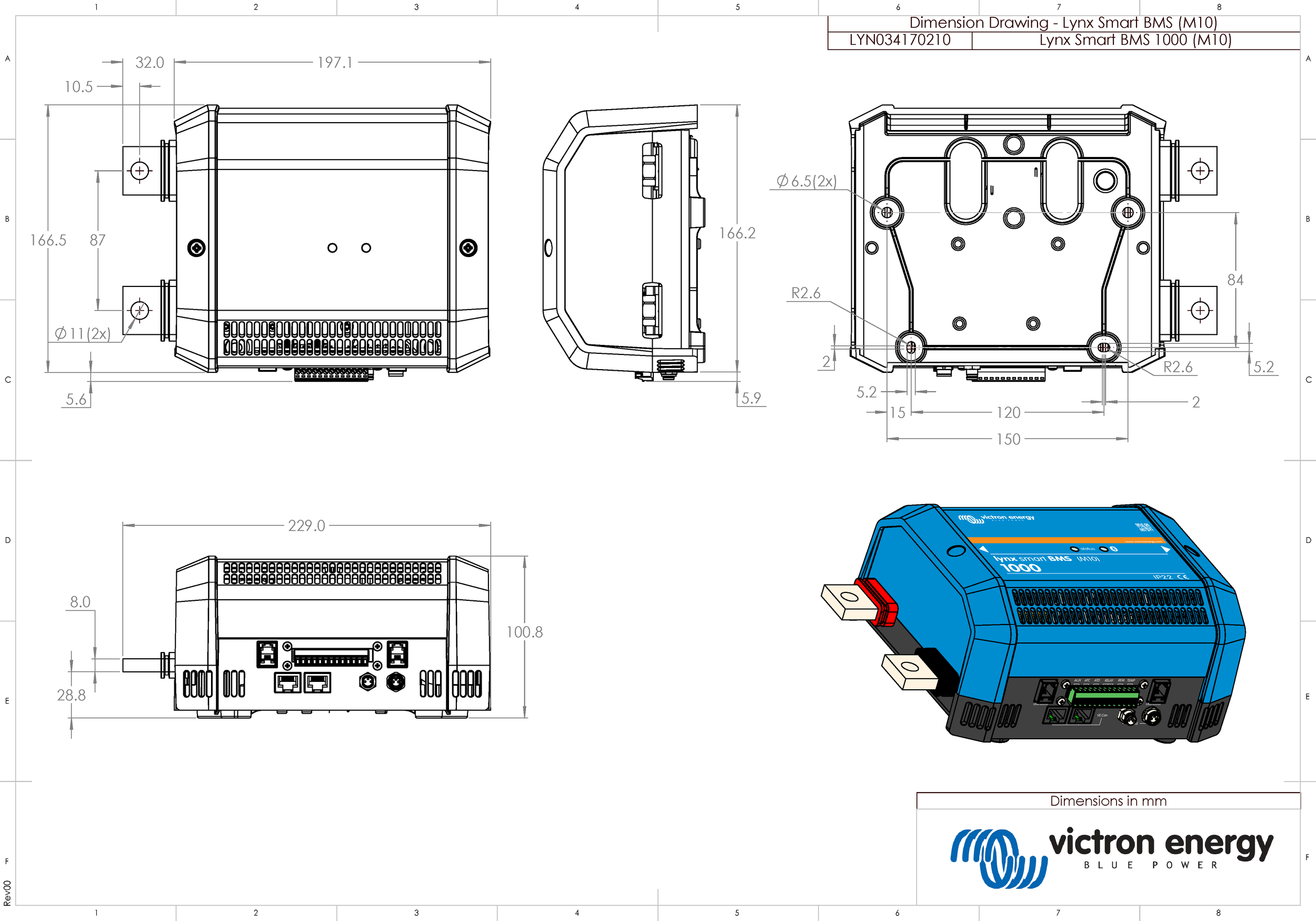
Lynx Smart BMS 1000 M10 model enclosure dimensions