7. Commissioning and Operation of the Lynx Smart BMS
7.1. Commissioning the Lynx Smart BMS
Commissioning sequence:
 | Check polarity of all battery cables. |
| Check cross sectional area of all battery cables. |
| Check that each battery has the most up to date firmware. |
| Check that if batteries have been connected in series, each battery has been fully pre-charged (refer to battery manual). |
| Check if all battery cable lugs have been crimped correctly. Check if all battery cable connections are tight (don’t exceed maximum torque). Tug slightly on each battery cable and see if the connections are tight. |
| Check all BMS cable connections and make sure the connector screw rings are screwed all the way down. |
| Check if each paralleled battery is fused or that each paralleled battery series string is fused. |
| If a GX device is used, check if the VE.Can cables and terminator have been placed and the device is powered from the AUX voltage output of the Lynx Smart BMS. |
| Power the Lynx Smart BMS by connecting the battery supply or placing the battery fuses and, if applicable, by switching the remote on/off switch to “on”. |
| Check that the load pre-charge is complete, the contactor is closed, and the loads are energised. |
| Connect to VictronConnect and make sure the Lynx Smart BMS has the latest firmware (see the Update firmware chapter for details) and that all settings have been made, in particular that the battery capacity and the number of paralleled batteries is set correctly. |
| Check that the system voltage has been set correctly. |
| Check if the fuse names of the Lynx Distributor (if applicable) are correctly named. |
| If a GX device is connected, check that it is powered from the Lynx Smart BMS AUX terminals. |
| Check that the Lynx Smart BMS displays correctly on the GX device. |
| Disconnect a random BMS cable and verify that the BMS is turning off all charge sources and all loads. Reconnect the BMS cable. |
| Turn on a load and check that the current is a negative current displayed on the GX device or the VictronConnect app. |
| Charge batteries fully and check that a 100% state of charge is displayed |
7.2. Powering up
The Lynx Smart BMS will power up when a battery is connected to the battery terminals and the Remote on/off switch is turned on (or the wire loop is placed in the remote on/off terminal).
The power up sequence follows these steps:
System check: A self-test that checks the internal and external voltages and contactor.
Pre-charge loads: The pre-charge circuit will pre charge capacitive loads such as inverters or inverter/ chargers before the contactor closes to prevent very high inrush current.
Contactor closes: The Lynx Smart BMS is operational and the power to the Lynx Distributor(s) is turned on.
Operational
Once powered up, the contactor is closed. The green status LED together with the blue Bluetooth LED on the Lynx Smart BMS and the green power LED on Lynx Distributor(s) are illuminated.

Lynx Smart BMS LEDs
7.3. BMS operating modes
The BMS in the Lynx Smart BMS communicates with the batteries and will safeguard them against low or high cell voltage as well as low or high temperatures. Such events are reported by the battery to the Lynx Smart BMS to take necessary action by turning off loads and/or inverter/chargers and chargers and either turning the Lynx Smart BMS off or on again, fully automatically or manually.
The Lynx Smart BMS has 3 modes of operation:
ON
This is the normal operating mode. All interfaces are operational, and the contactor is closed. If the Lynx Smart BMS was off due to low cell voltage or low SoC shutdown, it will exit OFF mode and return to ON mode when
it detects a charging voltage >11.7V (>23.4V for a 24V system or >46.8V for a 48V system) than the battery voltage on the system side or
when all cell voltages are higher than 3.2 V in case of a low cell voltage shutdown or
when all cell voltages are higher than 3.37V in case of a low SoC shutdown or
when it is turned back on via the Remote on/off switch or
when it is turned back on via the VictronConnect app.
The mode is also ON for a duration of 5 minutes with no charge voltage supplied when a Low Cell Voltage alarm was issued.
OFF
Lowest power mode. All interfaces are off, and the contactor is opened. This mode is used to prevent damaging batteries by draining them too low.
OFF is the mode the LSB will enter when using the Remote on/off switch or the soft switch in the VictronConnect app.
The Lynx Smart BMS will also switch to OFF mode with a 5 minute delay if:
one or more cells fall below 2.8V (adjustable in the battery) and no charge voltage has been detected during this time to prevent further discharge or
when the set discharge floor is reached and by then no sufficient charging voltage has been detected on the system side of the BMS.
Standby
The Lynx Smart BMS can be put into Standby mode via the soft switch in the VictronConnect app or via the GX device and is used when the boat is docked or the RV is parked to prevent accidental discharging and charging from sources on the system side. All systems will be shut down, except for equipment powered by the AUX power port from which we recommend for powering the GX device. This mode is not intended to be used when the boat or RV is in storage for a longer period. Therefore, when a low cell voltage or low SoC (as determined by the discharge floor setting in the BMS) is detected, the Lynx Smart BMS will automatically switch to OFF mode to prevent further battery discharge.
Note
The basic requirement for the soft switch to work in VictronConnect or in the GX device is that the contact between pins 10 and 11 of the multi connector is bridged with either a wire loop or a remote on/off switch.
See below tables for an overview of all 3 operating modes, how to switch them manually and the status of the interfaces:
Mode | Main contactor | ATC | ATD | AUX power output | VE.Can port | Bluetooth | Intended use |
|---|---|---|---|---|---|---|---|
On | Closed | On | On | Powered | Functional | On | Normal operating mode. All interfaces are operational. |
Standby | Open | Off | Off | Powered | Functional | On | All systems will be shut down, except for equipment powered by the AUX power port from which we recommend for powering the GX device. |
Off | Open | Off | Off | Off | Off | On | Lowest power mode. All interfaces are off, and the contactor is opened. |
Lynx Smart BMS device modes and status of the interfaces
Mode | Soft switch VictronConnect app | Soft switch GX device | Hard wired Remote on/off switch |
|---|---|---|---|
* Only possible from Standby mode | |||
ON | Yes | Yes* | Yes |
Standby | Yes | Yes | No |
OFF | Yes | No | Yes |
How to manually switch device modes
7.4. Lynx Smart BMS trigger
This section describes the behavior of the Lynx Smart BMS in case the pre-alarm threshold is reached or either a low or high cell voltage or low temperature event is triggered.
The limits for the pre-alarm threshold, low cell voltage and low temperature are set in the battery.
Pre-alarm
If a cell voltage drops and reaches the pre-alarm threshold, the programmable relay will activate, if configured to Alarm relay mode. This will give an advanced warning of an impending low cell voltage and before the loads are disabled. Pre-alarm is indicated by the red LED flashing 3 times every 4 seconds. The Lynx Smart BMS ensures a minimum delay of 30 seconds between enabling the pre-alarm and switching off the loads.
Low cell voltage cut off
If the cell voltage gets too low and has reached the low cell voltage threshold, the ATD contact opens and turns off all loads. If the Lynx Smart BMS is connected to a GX device, DVCC compatible inverters connected to the same GX device are also turned off. After 5 minutes without sufficient charge voltage on the system side of the BMS, it will shut down.
Low temperature or high cell voltage cut off
If a cell voltage becomes too high and has reached the high cell voltage threshold (3.75V hard coded in battery), or if the low temperature threshold (adjustable in battery) has been reached, the ATC contact opens and will turn off all chargers. If the Lynx Smart BMS is connected to a GX device, DVCC compatible chargers that are connected to the same GX device will be turned off as well.
7.5. Battery monitor operation
The Lynx Smart BMS has a built-in battery monitor. It measures battery voltage and current. Based on these measurements it calculates state of charge, time to go and keeps track of historical data, such as deepest discharge, average discharge and number of cycles.
7.6. Battery care
Once the Lynx Smart BMS is in operation, it is important to take care of the batteries.
These are the basic guidelines:
Avoid total discharge of the battery at all times and use the discharge floor setting to prevent this.
Familiarize yourself with the pre-alarm feature and act when pre-alarm is active to prevent a DC system shutdown.
Charge your batteries as soon as possible when the pre-alarm is active or the BMS has deactivated loads.
Minimize the time the batteries spend in a deeply discharged state as much as possible.
The batteries need to spend at least 2 hours in absorption charge mode each month to ensure sufficient time in balancing mode.
When leaving the system unattended for some time, make sure to either keep the batteries charged during that time or make sure the batteries are (almost) full and then disconnect the DC system from the battery. Do this by disconnecting the positive battery pole.
7.7. VictronConnect-Remote (VC-R) support*
VictronConnect-Remote functionality enables the Lynx Smart BMS to be accessed remotely through a GX product, via the VRM portal.
This powerful feature allows full product configuration (except Bluetooth) and monitoring from practically anywhere in the world using the VictronConnect app. The user interface experience is just like the Lynx Smart BMS were connected locally using Bluetooth.
Open the VictronConnect app and tap on the VRM button.
Click on the installation that includes the Lynx Smart BMS.
Click on the Devices button. A list with all available VE.Direct and VE.Can devices will show up.
Tap on the Lynx Smart BMS. The Lynx Smart BMS status screen is now displayed as if it were connected locally using Bluetooth
*Requires VictronConnect v5.70 or later and Venus OS v2.90 or later
7.8. VictronConnect Instant readout*
Battery voltage, current, state of charge and remaining running time at a glance. See what you want to know in seconds in the VictronConnect app Device list.
The advantage is that the data is available much faster, together with data from other Bluetooth smart devices, and the range exceeds that of a normal Bluetooth connection.
To enable Instant readout:
Open the VictronConnect app and tap on the entry for your Lynx Smart BMS.
Tap on the cog wheel icon in the top right hand corner.
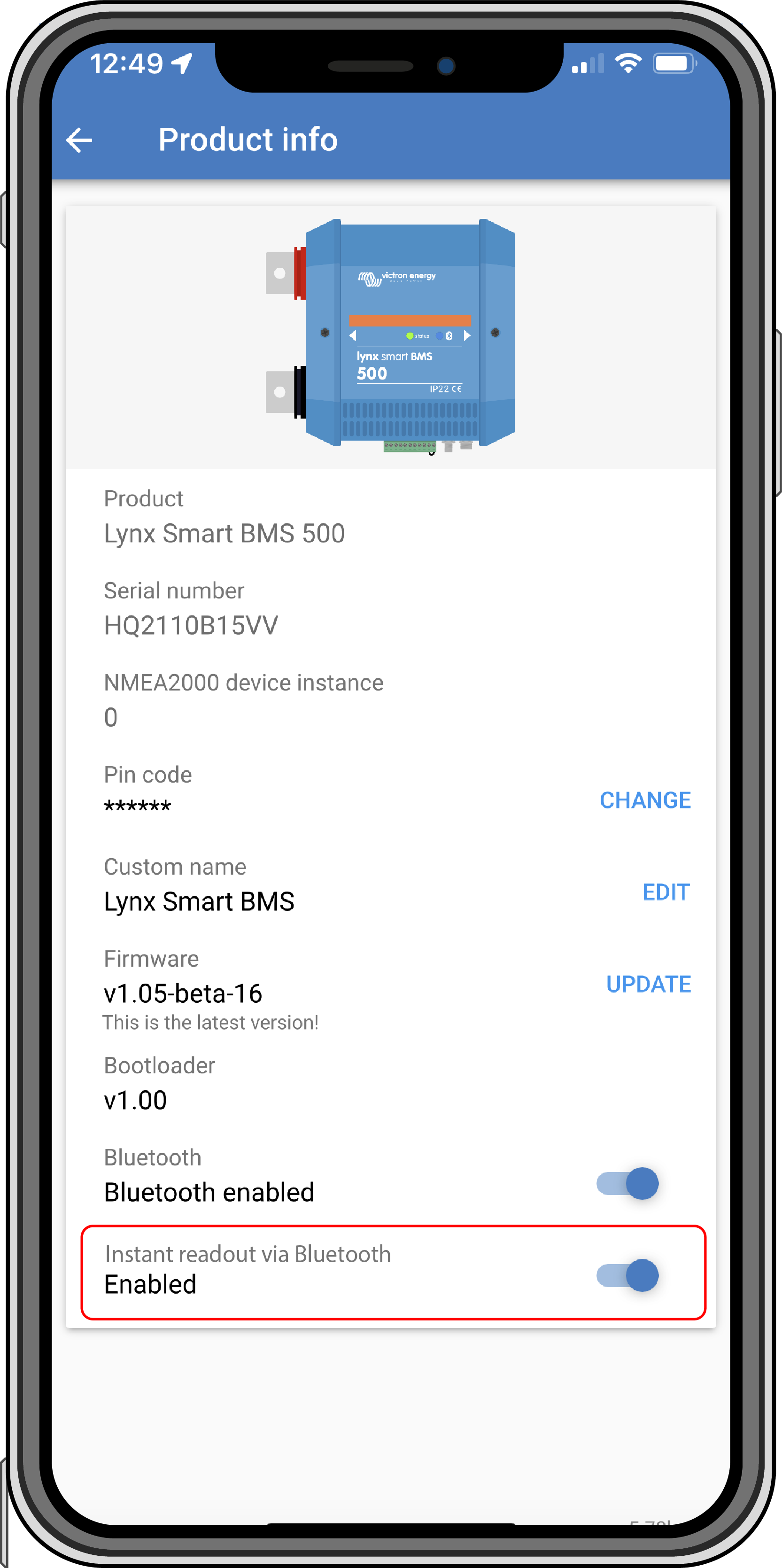
Tap on the 3 dots icon in the top right hand corner. The Product info screen opens.
Enable Instant readout by tapping on the slider. Be careful not to disable Bluetooth.
Go back to the local device list. Instant readout is now visible to the Lynx Smart BMS.
* Requires VictronConnect v5.70 or later
 |  |