4. Monitoring and control
4.1. VRM dashboard
4.1.1. Controls
Once Dynamic ESS has been set up, and its controls have been enabled on the Confirmation page, a Dynamic ESS control appears in the Controls menu on the VRM dashboard, where it can be switched on and off.
Select the Controls button at the top right of the VRM dashboard. | 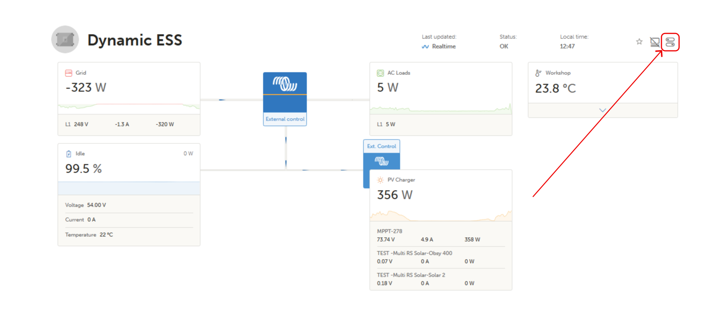 |
In the Controls panel, switch Dynamic ESS on or off using the toggle at the bottom. Depending on the site and the browser window size, it may be necessary to scroll to the bottom of the panel to see it. | 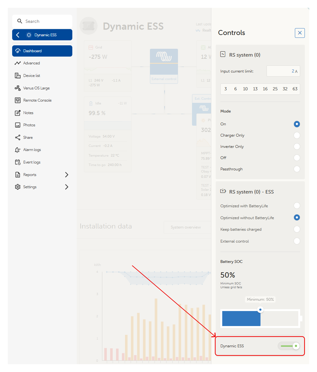 |
4.1.2. Dashboard graphs
When Dynamic ESS is enabled, additional graphs appear on the VRM dashboard. The graphs page has three tabs, Energy, Costs and earnings, and Schedule, selected from the upper left. A date control at the upper right moves between days, and a shaded "Now" band marks the current time. Values to the right of the "Now" band are forecasts.
Energy
The Energy tab shows two graphs. The upper graph plots the buy and sell energy prices across the day. The lower graph shows the energy flows between solar, battery, grid and consumption, for example solar to consumption, grid to battery, or battery to grid, as identified in the legend. | 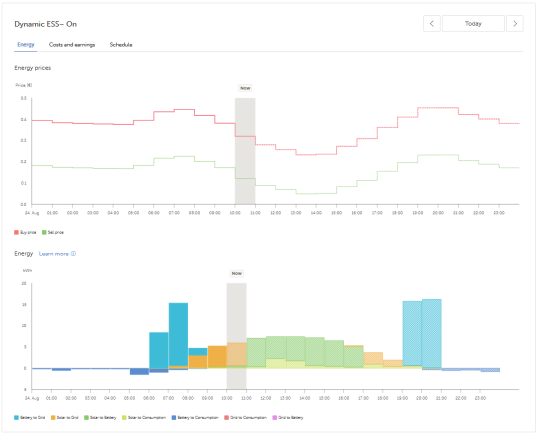 |
Costs and earnings
The Costs and earnings tab shows the costs incurred and the earnings made over the day. Energy bought from the grid and battery wear are shown as costs; energy exported to the grid is shown as earnings. A summary beneath the graph gives the grid earnings, battery costs and grid costs, together with the net total result. | 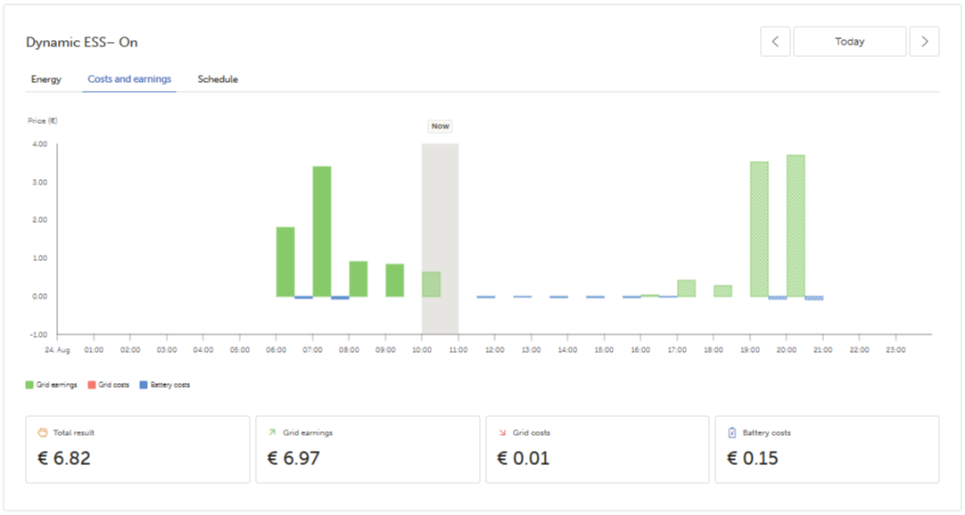 |
Schedule
The Schedule tab repeats the energy price graph at the top so it can be compared with the planned usage below. In the usage graph, bars below the axis represent energy drawn from a source, and bars above the axis represent battery charging or export to the grid. | 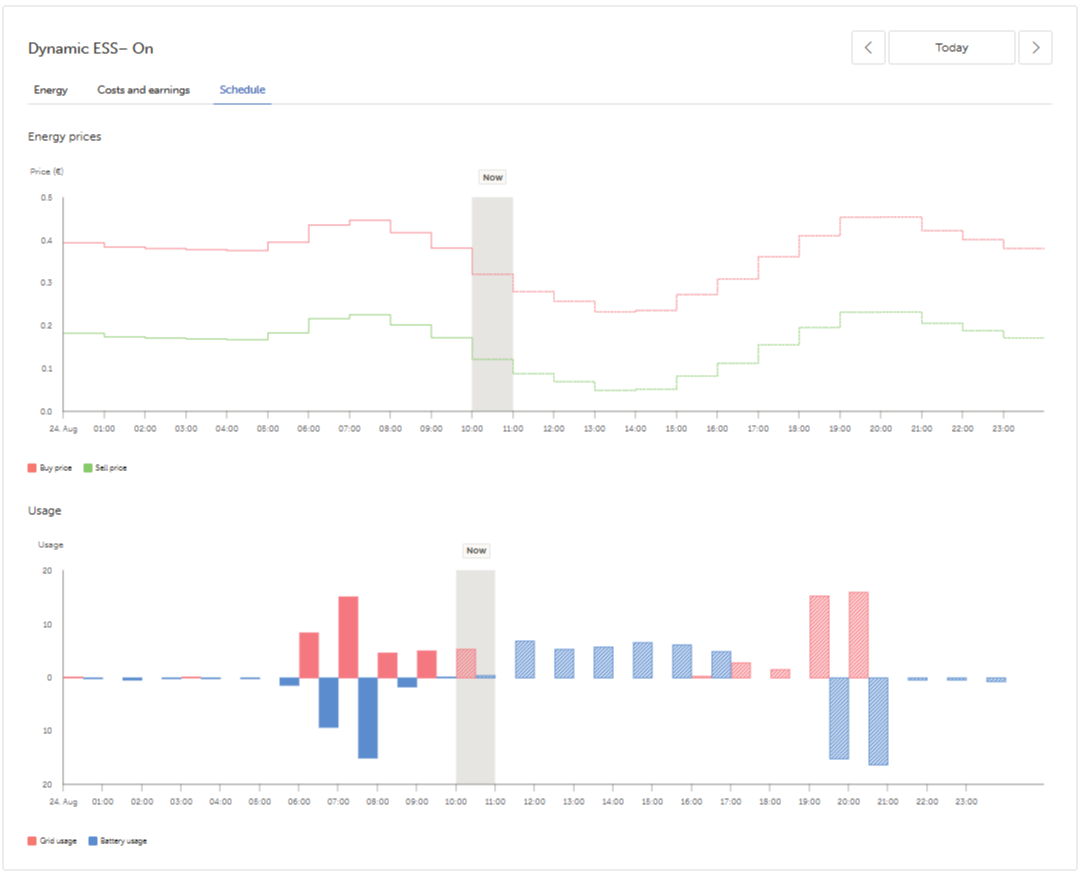 |
4.2. GX device menu
Dynamic ESS is set up in VRM. The GX device offers no setup options for Dynamic ESS, but it does provide a local read-out of what Dynamic ESS is doing, and allows Dynamic ESS to be switched on or off.
The location of the Dynamic ESS menu depends on the type of inverter/charger used.
Inverter/charger | GX device menu |
|---|---|
VE.Bus inverter/chargers such as MultiPlus Settings → System Setup → ESS → Dynamic ESS | 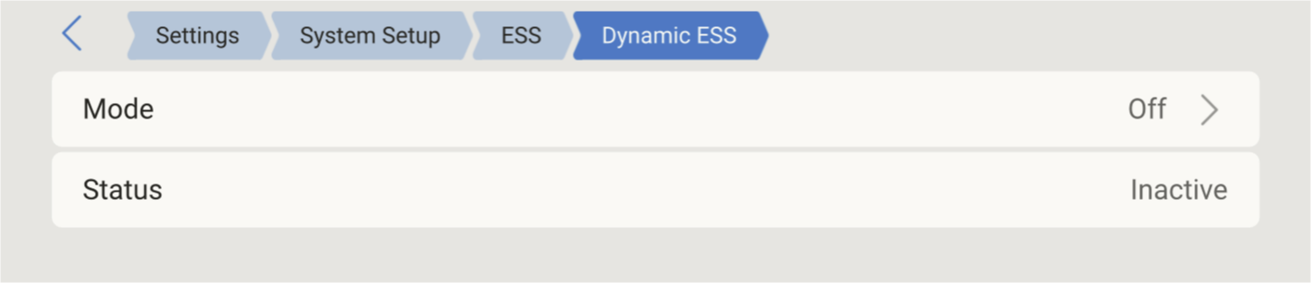 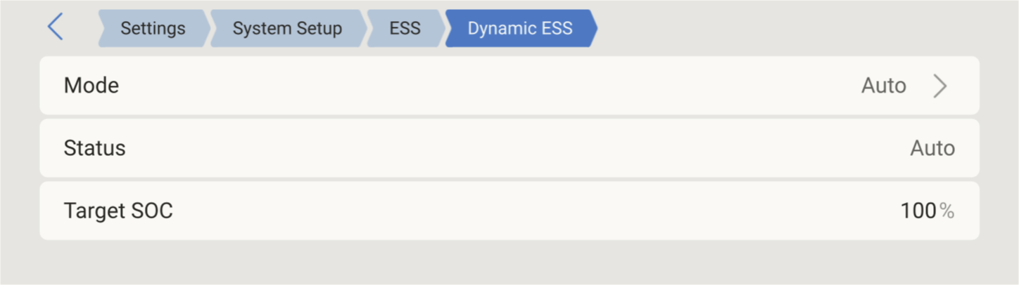 |
VE.Can inverter/chargers such as Multi RS Settings → Devices → RS system → ESS → Dynamic ESS | 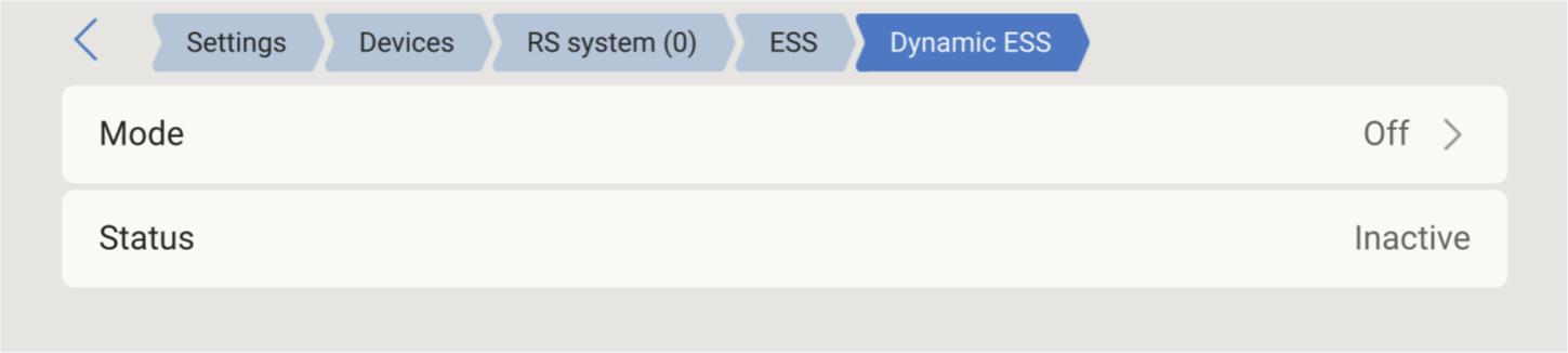 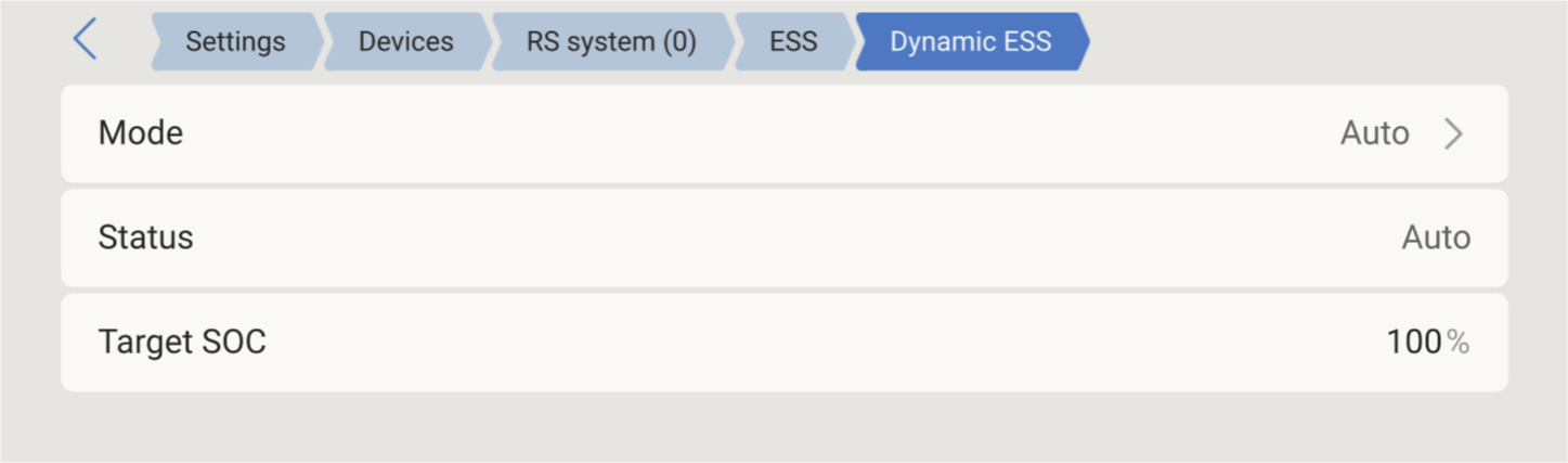 |
The menu contains the following items.
Item | Description |
|---|---|
Mode | The Dynamic ESS operating mode. Set Mode to Off to stop Dynamic ESS. Auto means the schedule supplied by VRM is being followed. Local means the schedule is supplied locally, by Node-RED, rather than by VRM. |
Status | Read-only. Shows what Dynamic ESS is doing at that moment. Status reads Inactive while Mode is set to Off. |
Target SOC | Read-only. The state of charge that Dynamic ESS aims to reach by the end of the current schedule interval. The value is updated with each new schedule interval. Only shown while Dynamic ESS is active. |