5. Installation
5.1. Mounting
The Blue Smart IP65 Charger range is designed to be used as a portable charger, or alternatively can be permanently mounted using the mounting tabs on the base of the charger.
Before mounting, the following aspects should be considered to identify/provide a suitable and safe location:
Install the charger in a location with good natural airflow/ventilation; in case airflow is a restricted, consider adding a cooling fan.
Ensure there is sufficient unobstructed space around the charger; a minimum clearance of 100mm above and below is recommended.
Install the charger on a non-flammable substrate and ensure there are no heat-sensitive items in the immediate vicinity; it is normal for the charger to become hot during operation.
Install the charger in a location where it is protected from environmental conditions such as water, high moisture and dust, and also located well away from any flammable liquids or gasses.
Do not install or place/operate the charger on top of the battery, directly above the battery, or in a sealed compartment with the battery; batteries can emit explosive gasses.
Do not cover or place any other items on top of the charger.
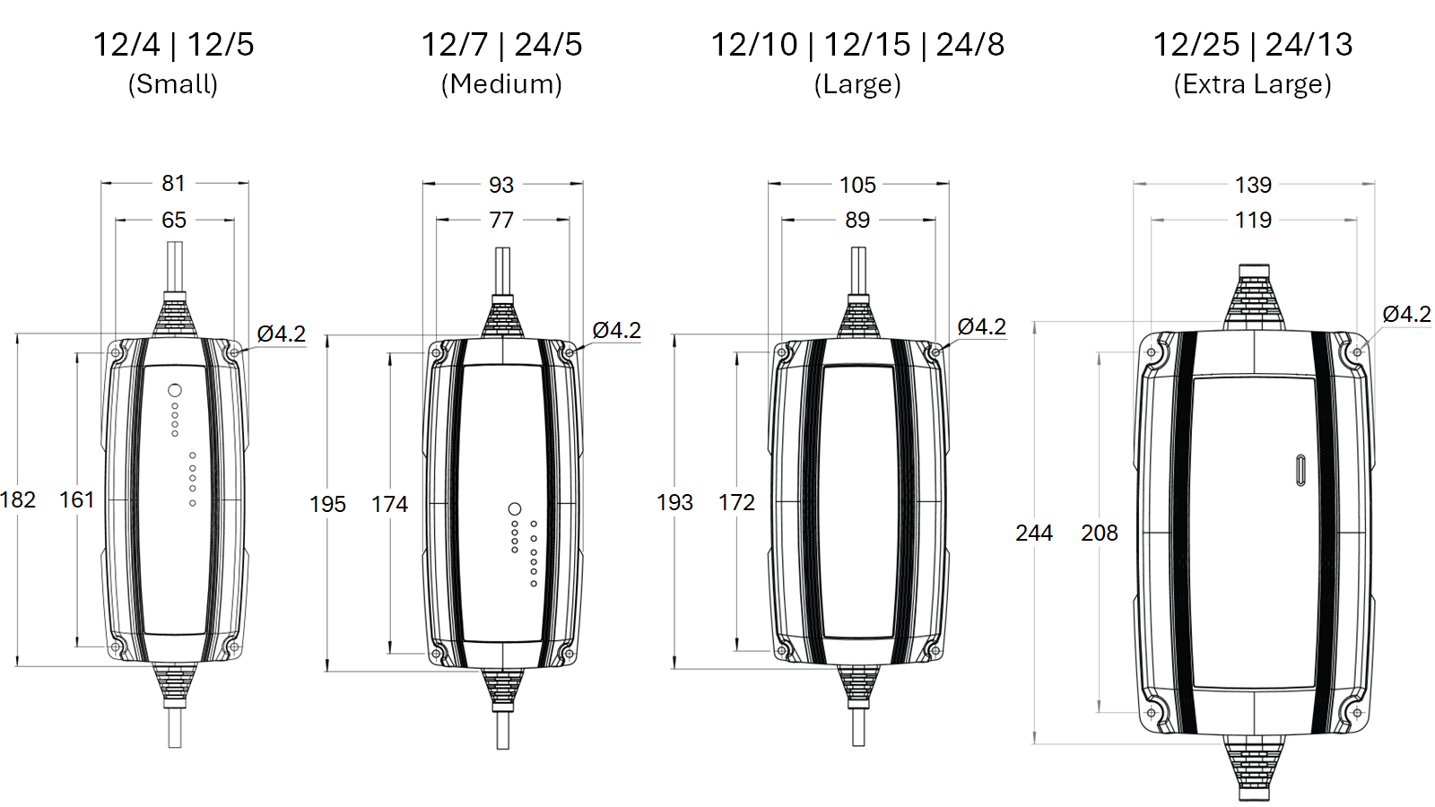
For permanent installations, mount the Blue Smart IP65 Charger vertically with the AC supply cable facing down; secure using suitable screws though the mounting holes.
Select and use screws with a pan/flange head (do not use screws with a countersunk/tapered head), and a screw thread outer diameter well matched to the mounting hole/slot internal diameter (~3mm max OD to provide a clearance fit).
To aid installation, it is recommended to hang the unit using the 2 upper screws (leave the screw heads ~3mm from the surface) and then install the 2 lower screws, before fully securing all 4 screws.
Take care to not over-tighten the mounting screws (as the mounting flanges are plastic).
Refer to the drawing below for mounting dimensions:
5.2. Wiring
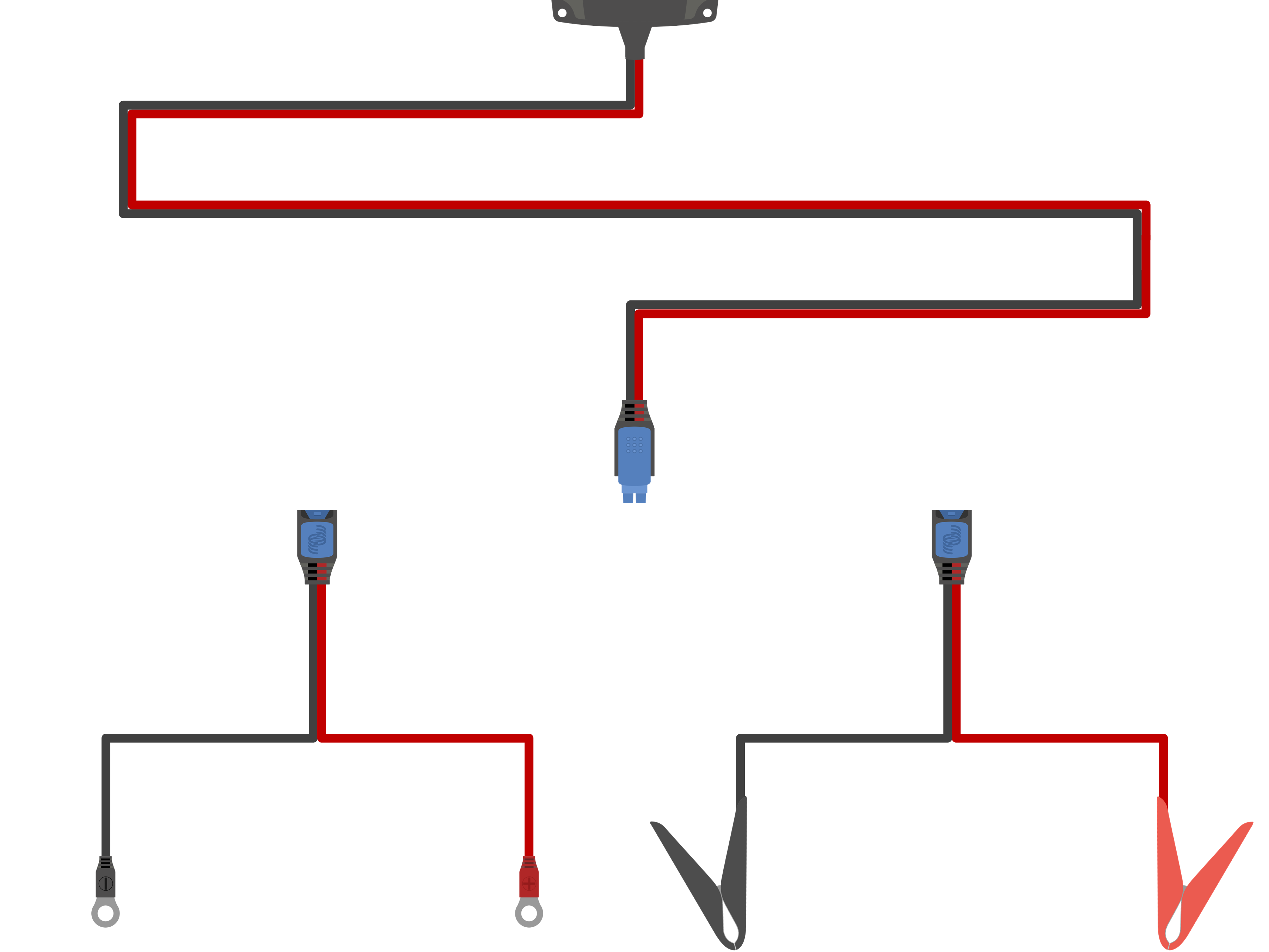
The Blue Smart IP65 Charger range includes suitable DC power cabling hardwired to the charger with interchangeable battery / DC system connection options; refer to the 'Installation > Wiring > DC power cable' section for more information.
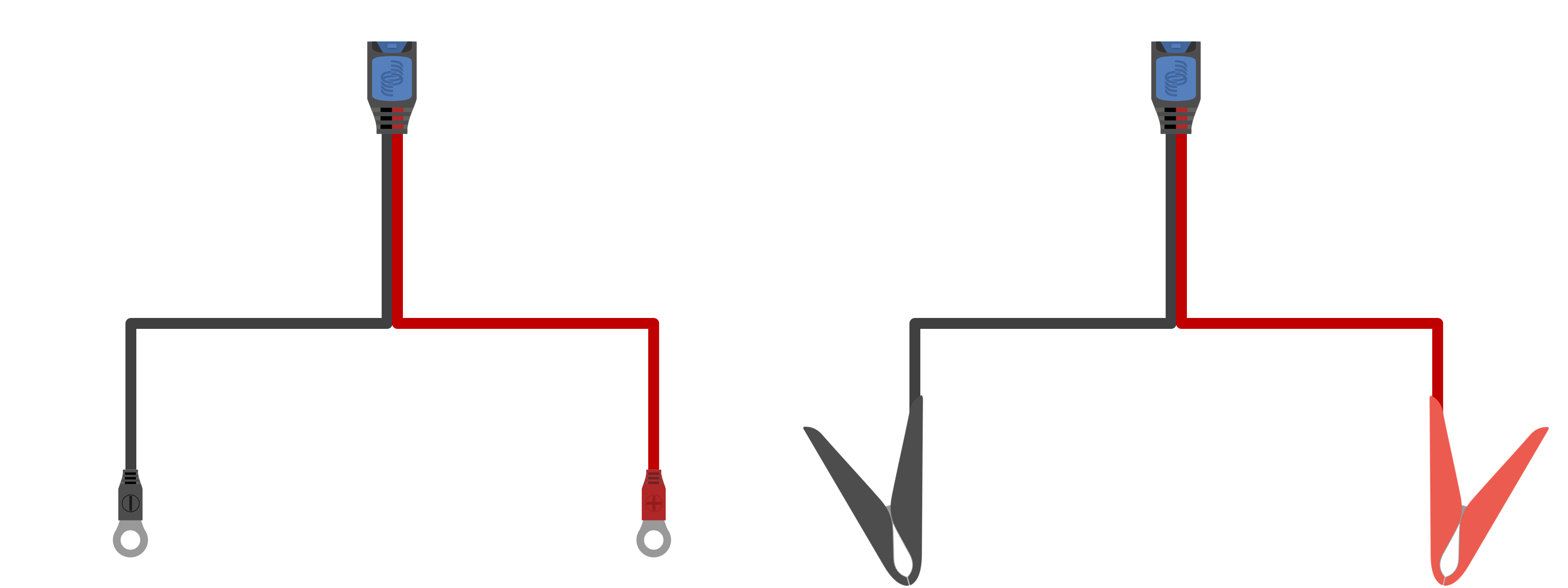
Select the interchangeable DC power cable battery connection type required for the installation; M8 ring terminals and battery clamps are supplied with the charger.
Other interchangeable DC power cable battery connection types and extension cables are available as an optional accessory; refer to the 'Installation > Wiring > DC power cable' section for more information.
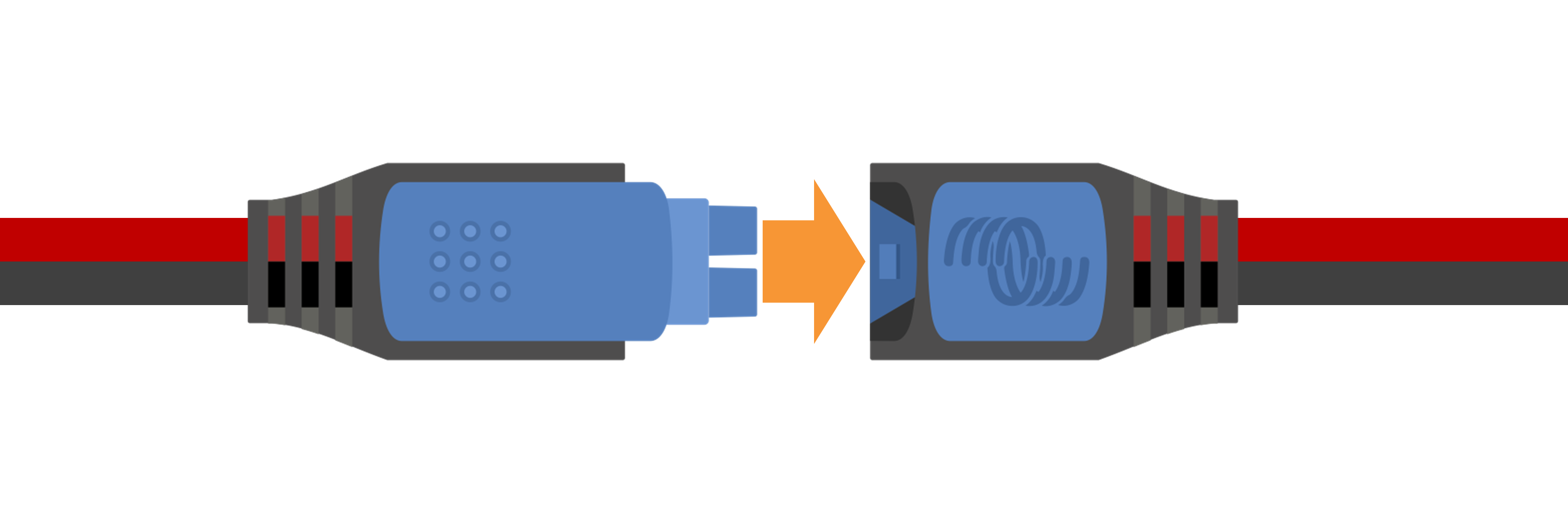
Connect the required DC power cable battery connection type to the DC power cabling hardwired to the charger; push the mating quick connectors together until the blue latch is fully engaged.
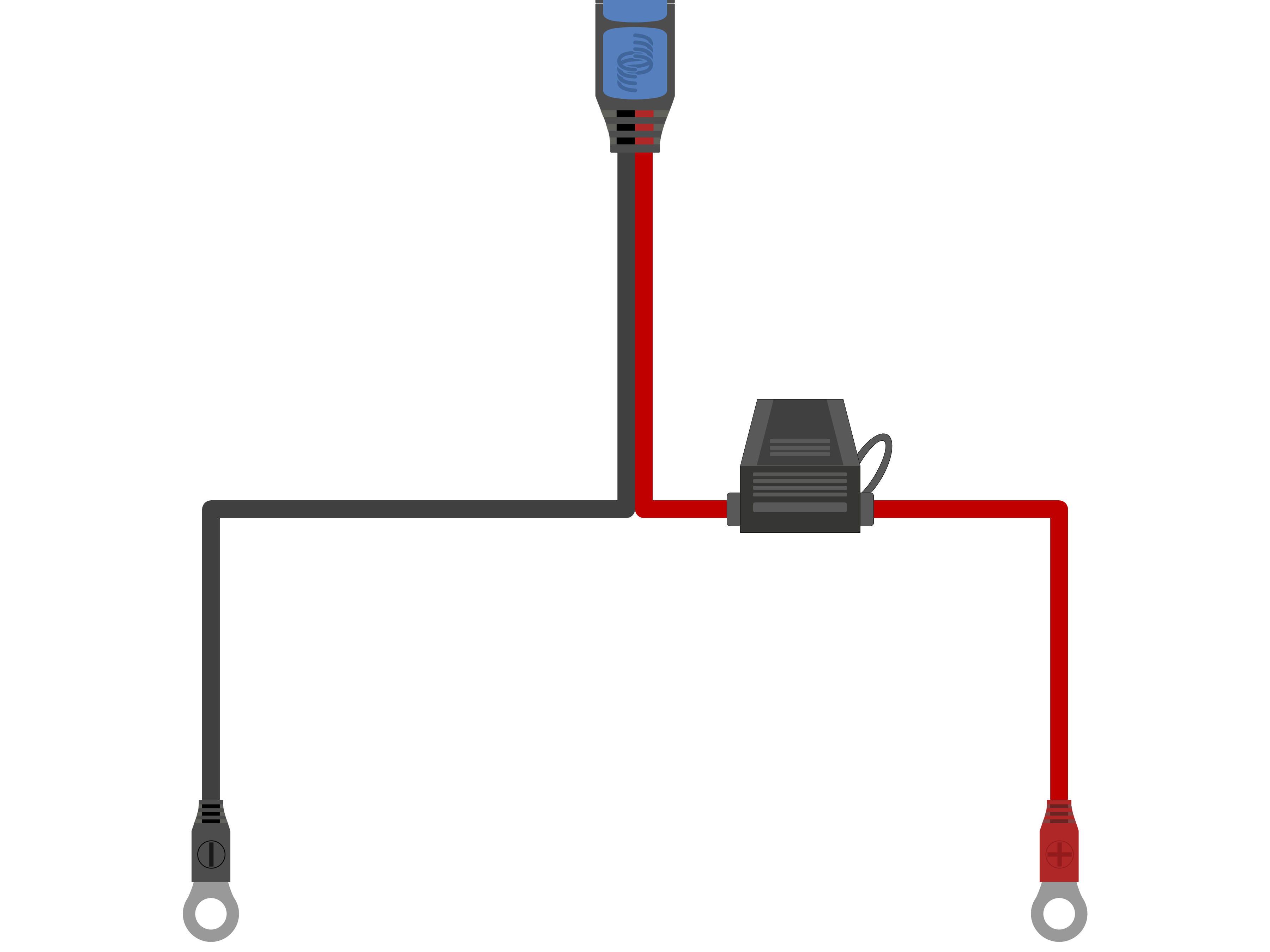
If applicable, install a suitably rated inline fuse or circuit breaker within the DC power cabling between the Blue Smart IP65 Charger and battery/batteries, located as close as practical to the battery/batteries; refer to the 'Installation > Wiring > Overcurrent protection' section for more information.
Connect the DC power cabling to the battery/batteries or DC system distribution bus - follow the instructions relevant to the installation type.
For hardwired installations, or when charging a battery outside of a vehicle/installation:
Ensure that the DC system is shut down (all DC loads and charge sources off/isolated) prior to disconnection of any existing battery / DC system distribution bus cabling and connection of the charger to the battery terminals / DC system distribution bus.
Connect the positive DC cable (red insulation) to the positive (+) terminal and the negative DC cable (black insulation) to the negative (-) terminal connection; ensure that the cable connection polarity is correct.
Torque all wiring termination hardware to manufacturers torque specifications using a suitable torque wrench and socket / screw driver bit.
For temporary installations when charging a battery installed within a vehicle, and the negative (-) battery terminal is grounded to the vehicle chassis (conventional):
Connect the positive DC cable / battery clamp (red insulation) directly to the battery positive (+) terminal first.
Then connect the negative DC cable / battery clamp (black insulation) to a suitable grounding point on the vehicle chassis (not directly to the negative battery terminal).
When disconnecting the charger, disconnect the DC cables / battery clamps in reverse of the connection order.
For temporary installations when charging a battery installed within a vehicle, and the positive (+) battery terminal is grounded to the vehicle chassis (unconventional):
Connect the negative DC cable / battery clamp (black insulation) directly to the battery negative (-) terminal first.
Then connect the positive DC cable / battery clamp (red insulation) to a suitable grounding point on the vehicle chassis (not directly to the positive battery terminal).
When disconnecting the charger, disconnect the DC cables / battery clamps in reverse of the connection order.
Connect the Blue Smart IP65 Charger AC power cable to a mains power outlet; after a short delay the TEST LED will begin to blink, until the charger determines if the battery will successfully accept charge (for up to 2 minutes).
Notice
Example wiring schematics depicting most typical installation configurations are also provided for reference; refer to the 'Installation > Schematics' section for more information.
5.2.1. DC power cable
The Blue Smart IP65 Charger range includes suitable DC power cabling hardwired to the charger with interchangeable battery / DC system connection options; M8 ring terminals and battery clamps are supplied with the charger.
The following interchangeable DC power cable battery connection types are also available as an optional accessory:
M6 ring terminals with inline ATO fuse (30A fuse included) - PN: BPC900100014
M8 ring terminals with inline ATO fuse (30A fuse included) - PN: BPC900110014
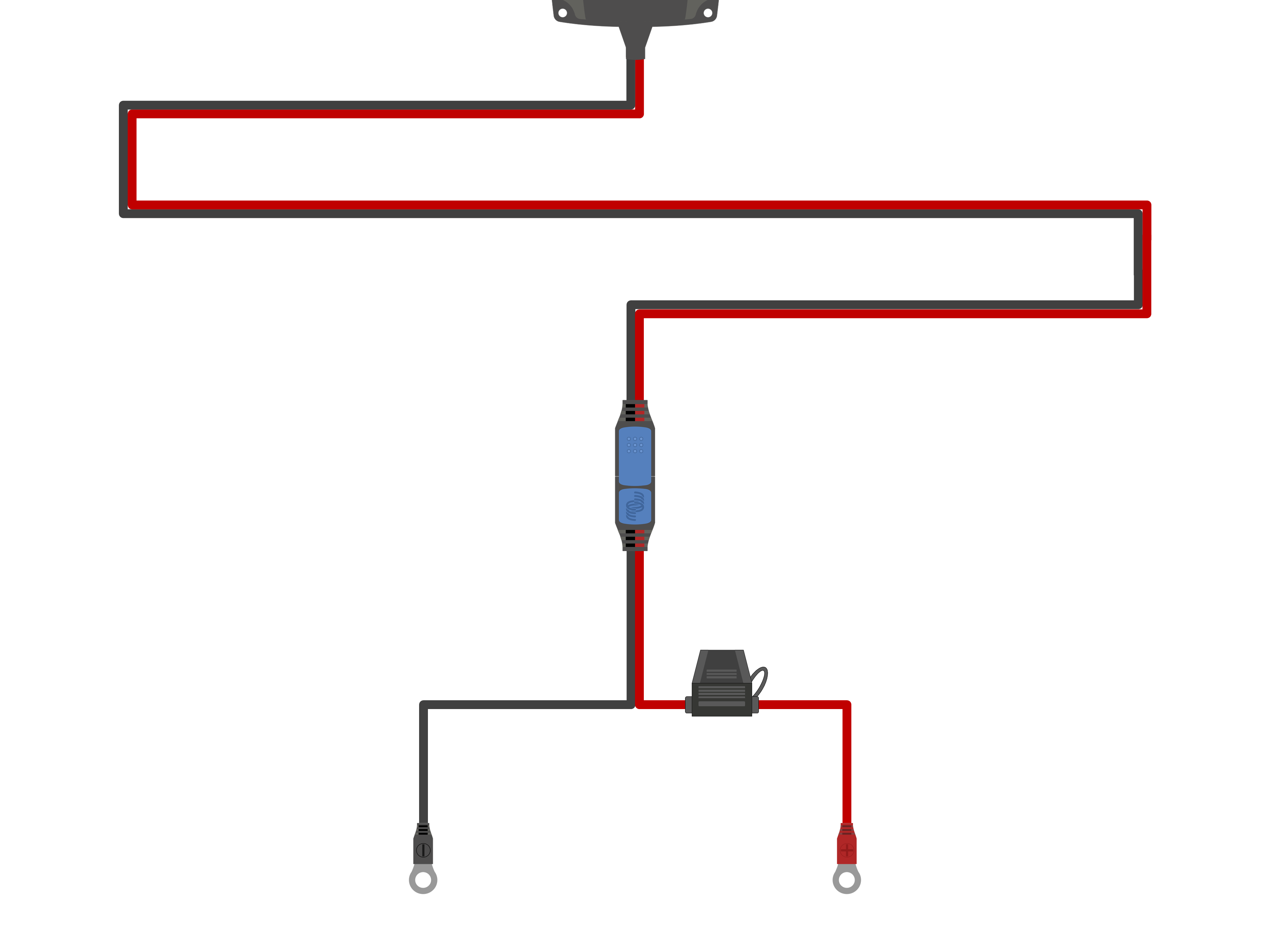
12V battery indicator quick connector with M8 ring terminals and inline ATO fuse (30A ATO fuse included, for use with lead-acid batteries only) - PN: BPC900120114
12V battery indicator panel with M8 ring terminals and inline ATO fuse (30A ATO fuse included, for use with lead-acid batteries only) - PN: BPC900110114
Spring clamps with inline ATO fuse (30A ATO fuse included) - PN: BPC900400014
12V cigarette lighter plug with integrated M205 fuse (16A fast bow M205 fuse included) - PN: BPC900300014
MagCode 12V Power Clip (15A max) - PN: BPC900500014
MagCode Power Port (15A max) - PN: BPC900520014
2m extension cable - PN: BPC900200014
Refer to the table below for the DC power cable size/gauge (cross sectional area) supplied with each Blue Smart IP65 Charger model:
5.2.2. Overcurrent protection
To ensure reliable and safe operation, it is recommended to install a suitably rated inline fuse or circuit breaker within the DC power cabling between the Blue Smart IP65 Charger and battery/batteries, located as close as practical to the battery/batteries; this is particularly important for hardwired installations.
The primary purpose of an inline fuse or circuit breaker located close to the battery/batteries (energy source) is to protect the cabling and system in the event of a overcurrent fault, such as a short circuit in the DC power cabling; a fuse or circuit breaker located in the charger unit or nearby within the DC power cabling will not provide protection from a short circuit in the unprotected length of cabling.
In the event of a short circuit in the DC power cabling between the battery/batteries and charger, the battery/batteries have the capability to provide extremely high current through the DC power cabling, which can result in severe overheating of the cabling and potentially a fire unless the battery/batteries (energy source) is promptly disconnected by a suitable fuse or circuit breaker.
Note that other Blue Smart IP65 Charger interchangeable DC power cable battery connection types are available as an optional accessory, including cables with an integrated inline fuse; refer to the 'Installation > Wiring > DC power cable' section for more information.
Refer to the table below for the recommended fuse / circuit breaker rating, depending on the charger model:
Notice
The fuse / circuit breaker rating recommendations above are based on a 75% maximum normal operating current limit for the minimum fuse / circuit breaker rating and the maximum current capability of the related DC power cabling size/gauge for the maximum fuse / circuit breaker rating; these recommendations are generic and do not cover the intricacies of all installations and/or fuse / circuit breaker types, please consult a certified installer for guidance with specific and/or complex installations.
5.3. Schematics
5.3.1. Basic install
Refer to the wiring schematic below to connect a Blue Smart IP65 Charger to a single battery / battery bank:
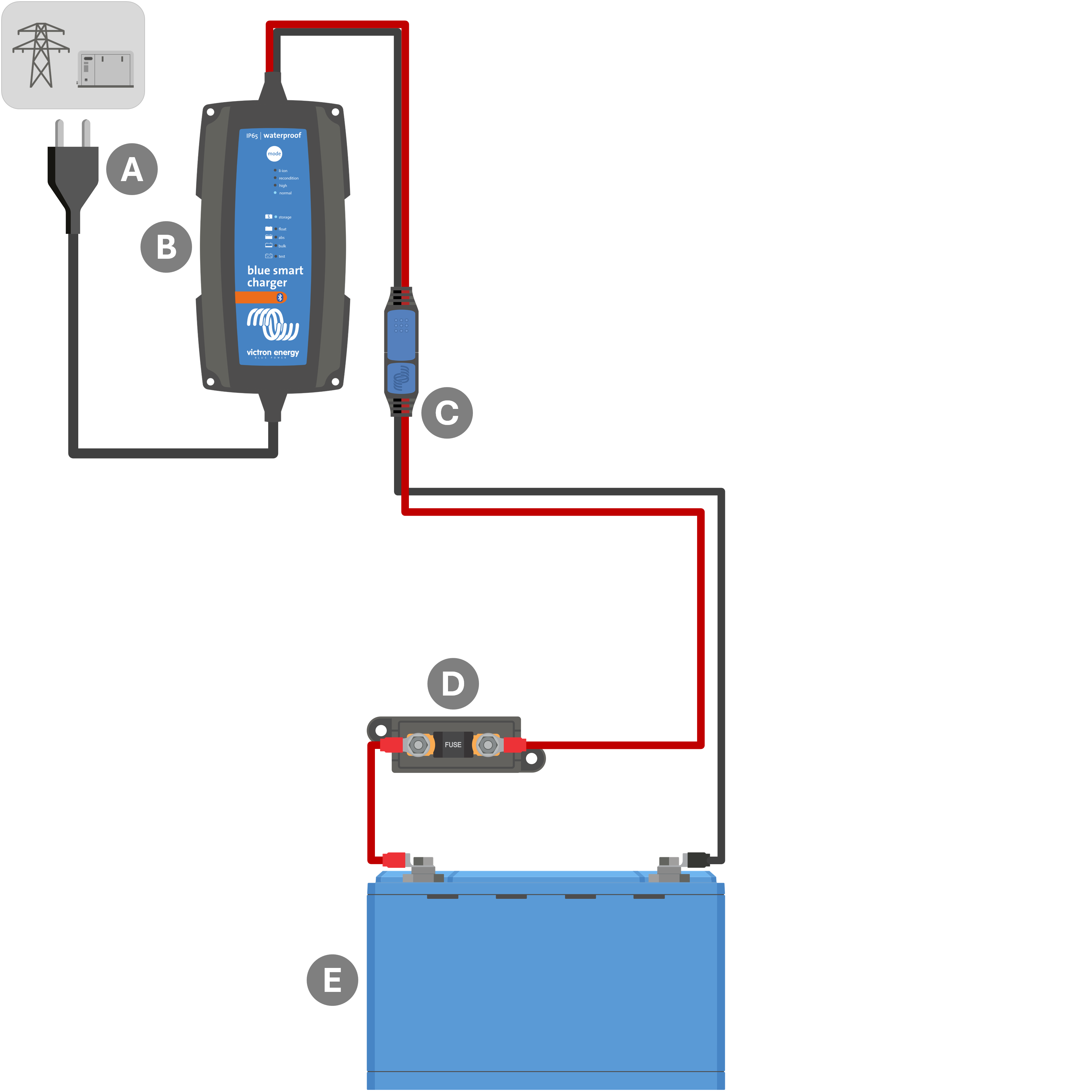
Key | Description |
|---|---|
A | AC power supply (mains power grid, generator or inverter) |
B | Blue Smart IP65 Charger |
C | Interchangeable DC power cable battery connection with ring terminals (Other battery connection types are available as an optional accessory; refer to the 'Installation > Wiring > DC power cable' section for more information) |
D | Fuse / circuit breaker (locate as close as practical to battery) |
E | Battery / battery bank |
5.3.2. System with multiple chargers
Refer to the wiring schematic below to connect multiple Blue Smart IP65 Chargers in parallel to a single battery / battery bank:
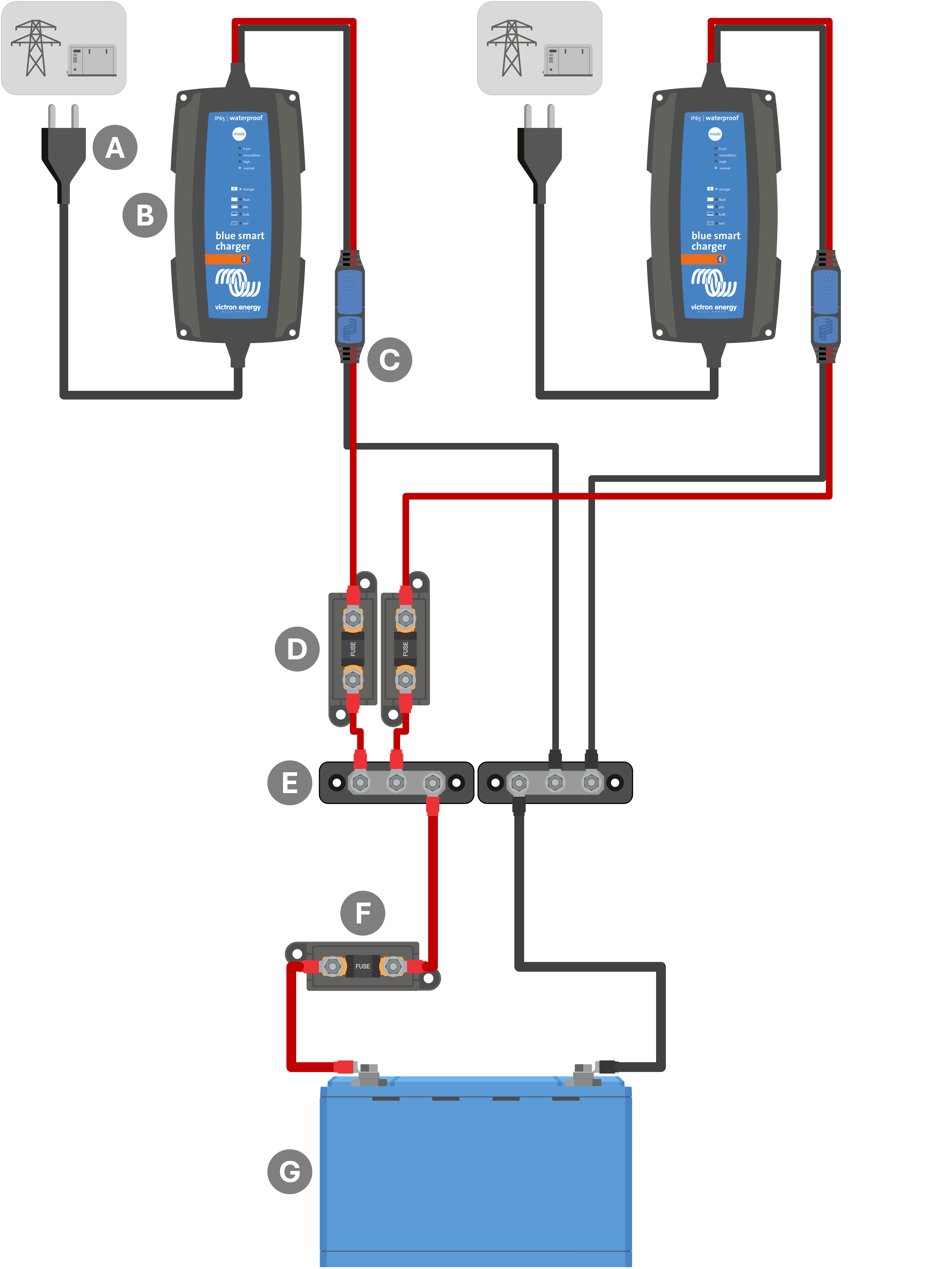
Key | Description |
|---|---|
A | AC power supply x2 (mains power grid, generator or inverter) |
B | Blue Smart IP65 Chargers x2 |
C | Interchangeable DC power cable battery connection with ring terminals (Other battery connection types are available as an optional accessory; refer to the 'Installation > Wiring > DC power cable' section for more information) |
D | Fuses / circuit breakers x2 (locate as close as practical to DC positive busbar) |
E | DC positive and negative busbar |
F | Fuse / circuit breaker (locate as close as practical to battery) |
G | Battery / battery bank |
Notice
Multiple Blue Smart IP65 Chargers connected in parallel must all have the same charge settings.