 Add this page to your book
  Remove this page from your book
  Manage book (
 Help
Help Table of Contents
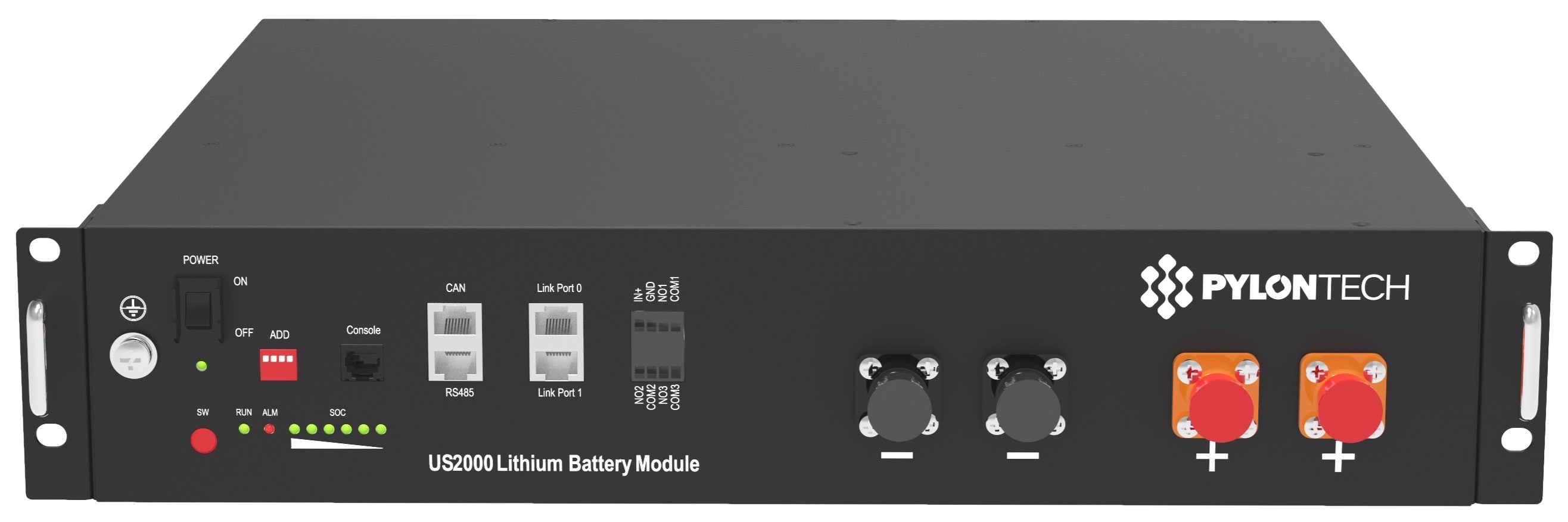
Victron & Pylontech UP2500, US2000(C/D), US3000, US3000C, US5000, US5000B, UF5000, Pelio-L, UP5000, Phantom-S, Force-L1 & L2
The combination of Victron products with Pylontech lithium batteries has been tested and certified by the Victron and Pylontech R&D departments.
General information about the battery is found in Pylontech's documentation.
This manual is intended to be used in conjunction with the product manual supplied by Pylontech. It provides additional and specific information regarding integration with Victron systems.
The Pylontech includes a Battery Management System (BMS) with each battery module. This interfaces with the Victron GX device and can support multiple battery modules connected in parallel.
1. Product & system compatibility
| Battery | UP2500* | US2000 (Plus/C/D) | US3000(C) | UP5000 & US5000(B) | Pelio-L | Force-L1 & L2 | UF5000 |
|---|---|---|---|---|---|---|---|
| Nominal voltage | 24V | 48V | 48V | 48V | 51.2V | 48V | 51.2V |
| Module capacity | 2.55 kWh | 2.4 kWh | 3.5 kWh | 4.8 kwh | 5.12kWh | 3.55 kWh | Coming soon |
| Minimum Venus firmware | v3.50 | v3.50 | v3.50 | v3.50 | v3.50 | v3.50 | v3.50 |
24V: UP2500 48V: US2000, US3000, US2000C/D, US3000C, US5000, US5000B, UP5000, Phantom-S, Force-L1 & L2 51.2V: Pelio-L, UF5000
* Note that UP2500 came in two versions, UP2500NA01V00101 does not have a CANBUS port, and IS NOT supported by Victron. UP2500NB01V00101 released April 2020 has the CANBUS port and IS supported.
1.1 Offgrid, Backup and Energy Storage Systems are possible
Victron + Pylontech can be used for the following system types:
- Off-grid (DVCC)
- Energy Storage Systems (ESS) - Self Consumption (ESS - Start page)
1.2 A GX-device is required, eg Cerbo GX or Venus GX (VGX)
It is essential to use the CAN-bus connection of the GX device (e.g. Cerbo GX) - this communicates the keep-alive signal, charge and discharge limits, error codes and state of charge (SOC %) between the batteries and the system.
For new systems, the minimum required firmware version for the GX Device (e.g. Cerbo GX is v2.42. It is highly recommended to use the latest firmware version on all connected devices, including the GX device Inverter/Charger and MPPTs. There are regular updates to improve performance and reliability.
Legacy systems installed with v2.15 can continue to be used without upgrade as long as they do not present any issues.
1.3 All Multi, MultiPlus, MultiGrid and Quattro are compatible
As long as you are using the appropriate model for the nominal battery voltage, all VE.Bus inverters and inverter/chargers are compatible.
The minimum firmware version for new installations is 469. Though updating to the latest firmware is recommended where possible, and a necessary first step when troubleshooting issues.
These inverter/charger units must be connected to the GX device via the VE.Bus connection port.
Legacy systems installed with VE.Bus firmware 422 can continue to be used without upgrade as long as they do not present any issues.
1.4 All VE.Direct BlueSolar and SmartSolar MPPT Chargers are compatible
For proper operation, the Pylontech battery needs to be able to control the charge current. Therefor it is recommended to use Victron 48V compatible MPPTs models with VE.Direct port for charging.
MPPTs with a VE.Direct port
MPPTs are controlled via the GX device. Make sure the GX device runs v2.15 or later, and the MPPTs to 1.37 or the latest available version.
The MPPT requires connection to the GX device to regulate charge currents as the batteries require (due to temperature, etc) To test operation, try disconnecting the GX device from the MPPT. After a time-out, the MPPT will stop charging and flash an error code on its LEDs. The error code is error #67: no BMS.
MPPTs with a VE.Can port
New Model (2019 and later) VE.Can MPPTs are also supported from firmware version 1.06 and above. Be aware that some GX devices (e.g. CCGX) only have a single CANBus interface, and that is required for the battery communications. So if you use a new VE.Can MPPT, it must also be with a GX device that has more than one CANbus interface, e.g. the Cerbo GX.
Old model VE.Can MPPTs (pre 2019) are not supported.
2. Minimum Battery Sizing Recommendations
Once DVCC is enabled on the GX device, the charge and discharge rates are managed by the Pylontech battery.
Using very large solar arrays with battery banks that are too small can exceed the limits of the batteries ability to charge and possibly lead to the BMS triggering over-current alarms.
You must have the minimum number of battery modules to supply the inverters startup inrush surge currents that charge the capacitors when the inverter is first connected, this occurs prior to any loads being connected. There is also the subsequent potential current demands of the loads connected to the inverter. It is much more desirable to have the inverter/charger overload than the battery, as the inverter will automatically recover, whereas the battery may require intervention once in a fault state.
These minimum battery sizings are required for reliable operation.
An example of minimum system sizing based on the US2000 battery module is below. Each battery module is approximately 50Ah at 48V, can provide 25A continuous charge and discharge and 100A peak for 1 minute.
| Inverter / Charger Model | Inv continuous watts @ 25 degrees | Inverter peak watts surge rating | Number of Pylontech modules | Battery continuous discharge watt rating | Battery peak discharge watt rating |
|---|---|---|---|---|---|
| Multiplus 48/500/6 | 430 | 900 | 1 | 1200 | 4800 |
| Multiplus 48/800/9 | 700 | 1600 | 1 | 1200 | 4800 |
| Multiplus 48/1200/13 | 1000 | 2400 | 1 | 1200 | 4800 |
| Multiplus 48/3000/35 | 2400 | 6000 | 2 | 2400 | 9600 |
| Multiplus 48/5000/70 | 4000 | 10000 | 4 | 4800 | 19200 |
| Quattro 48/8000/110-100/100 | 6500 | 16000 | 6 | 7200 | 28800 |
| Quattro 48/10000/140-100/100 | 8000 | 20000 | 7 | 8400 | 33600 |
| Quattro 48/15000/200-100/100 | 12000 | 25000 | 10 | 12000 | 48000 |
3. CAN-bus Wiring
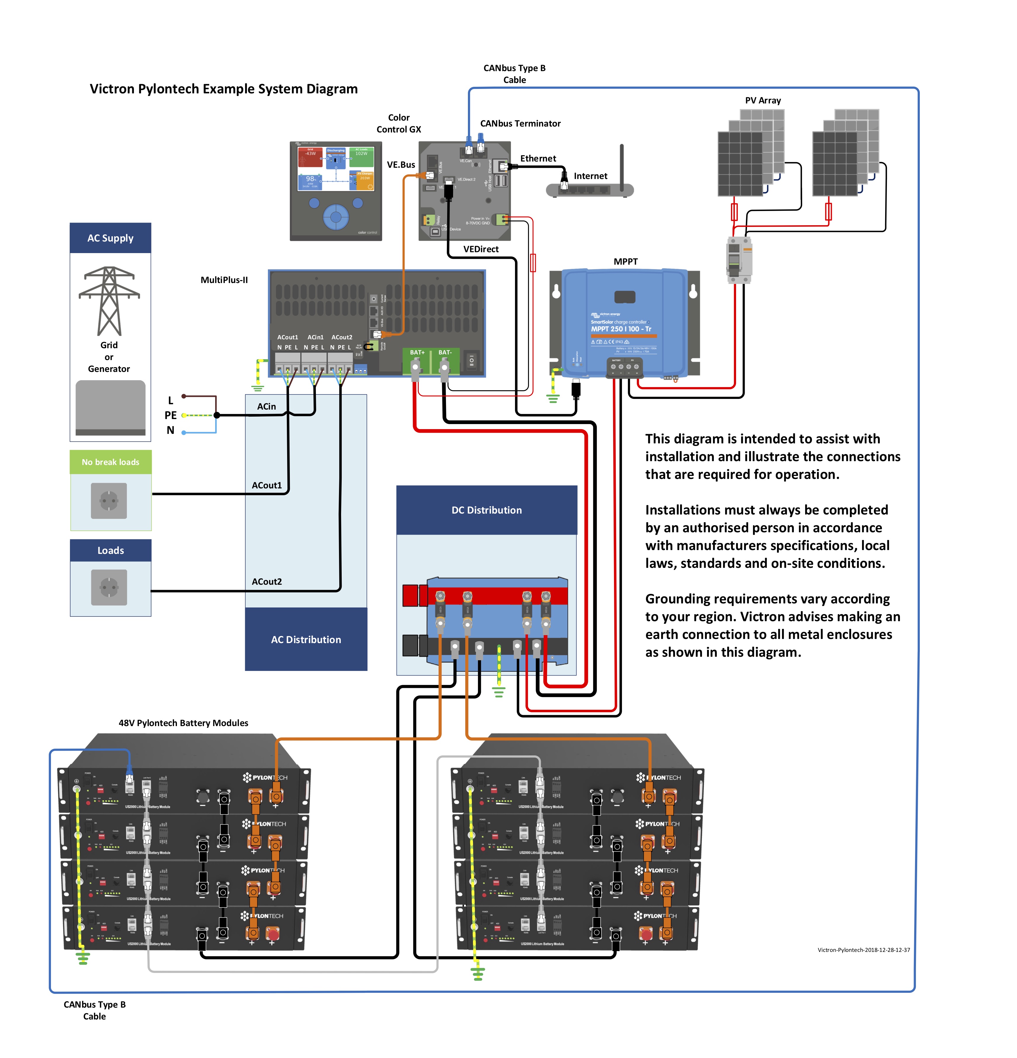
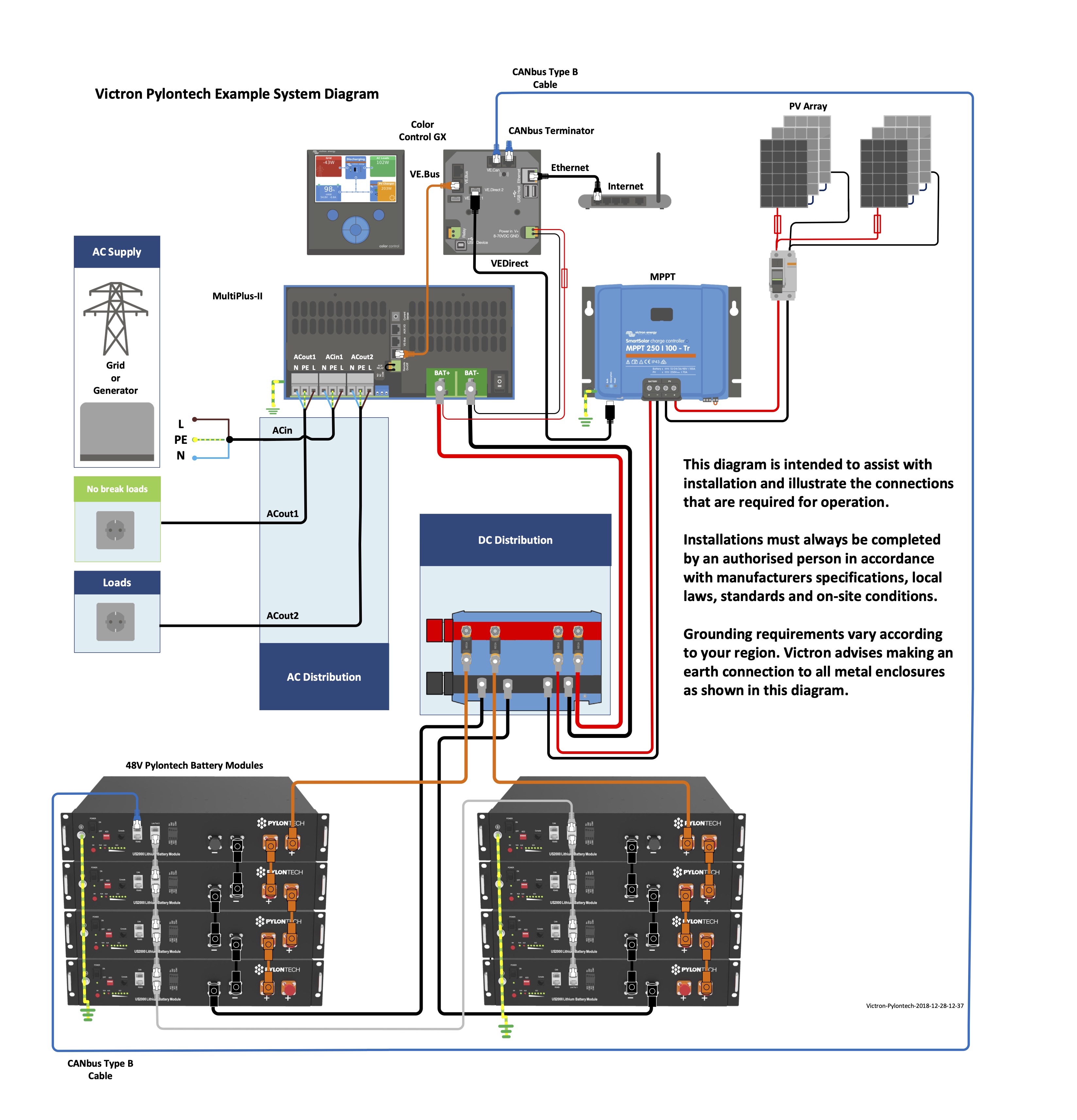
You can connect multiple battery modules together to form a single large battery by connecting the RJ-45 cable supplied by Pylontech using the link ports on the battery. This is shown in more detail in the example wiring diagram and Pylontech manual.
The communications for UP2500 can be paralleled up to 20 modules per string (and cannot use the LV-HUB). Other models can connect up to 8 battery modules (see Pylontech data sheets), in those models when using more than 8 parallel units, some limitations, additional configuration or equipment (e.g. Pylontech LV-Hub) may apply. See your Pylontech dealer, and Pylontech documentation for more details.
The batteries will automatically detect and link to each other, no adjustment of dip switches on the battery module are necessary.
The battery with the empty link port 0 is the master battery.
Important note on DIP switches
No adjustment to the DIP switches is necessary, unless you are using a LV-Hub to connect a large number of modules. The address DIP-switches must be set to 000 for correct operation, and the GX device will not detect the battery if you use any other setting. Larger batteries using an LV-Hub is discussed later in this document.
Type A cable
The Victron VE.Can to CAN-bus BMS type A Cable, part number ASS030710018 is used for connection with US2000C/D / US3000C / UP5000 / US5000 / US5000B / Force-L.
Type B cable
The Victron VE.Can to CAN-bus BMS type B Cable, part number ASS030720018 is used for connection with US2000 / US3000 / UP2500;
Note you cannot use the comms cable supplied by Pylontech for this connection between the master battery and the GX device.
Connections
Plug the communication cable with the side which is labeled Battery BMS into the Pylontech CAN port of the master battery.
Some GX devices (such as the Cerbo GX), have multiple CAN ports. If your GX device has a BMS-Can port, this should be used. If your GX device ONLY has VE.Can ports, you will need to change the VE.Can port profile to CAN-bus BMS (500 kbit/s) for the battery (and then it cannot be used for other VE.Can devices).

Plug the side labeled Victron VE.Can into the GX device.
Then, plug a VE.Can terminator in the other VE.Can socket on the GX device. Two VE.Can terminators are included with the package of the GX device as an accessory, only one is used. Keep the other one as a spare.
More information about the cable can be found in its manual.
Without properly connecting this cable, the battery will not show up on the display of the GX device. The battery will also turn itself off.
It is important to ensure this connection and display of the battery on the GX device display before attempting firmware updates or settings changes on other devices if they depend on the power supply from the battery. Without this connection, the battery may turn off unexpectedly.
4. GX Device Settings
When the Pylontech battery is connected to the BMS-Can port of a GX device (running v2.80 and later) the following DVCC settings will be set and enforced automatically.
If you are running a GX firmware version prior to this, these will need to be manually configured.
Manual Configuration
On the GX device,
- If your GX device has a BMS-Can port, the battery should be connected to this.
- If you connect the BMS to the VE.Can port you will need to adjust the port speed. Select the CAN-bus BMS (500 kbit/s) CAN-profile in the GX device. Menu path: Settings → Services → VE.CAN port.
After properly wiring and setting the correct CAN-bus speed, the Pylontech will be visible as a battery in the device list. If you have multiple batteries a single entry will show up, which represents all batteries:
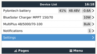
Next, go to Settings, DVCC, and configure as follows:
| Venus Settings → System Setup Parameter | Value |
|---|---|
| DVCC | ON |
| Shared Voltage Sense | OFF |
| Shared Temperature Sense | OFF |
For more information about the behaviour of DVCC, please see the GX device manual.
Additional optional controls
Note: The “Limit managed battery charge voltage” feature should be left OFF, unless you are experiencing “High Voltage” or “Internal Error” alarms. These alarms can indicate that there is an internal cell imbalance in the battery. It may be useful in this situation to enable this feature, and then adjust the voltage limit down so that the batteries are able to balance charge without reaching over voltage internally. This imbalance is at a cell level, so might not be reflected as a high overall battery voltage if measured with a Multimeter. This can then be turned off once the battery has balanced itself properly.
The 'limit charge current' value that you set manually in the DVCC menu of the GX device will allow you to set a value less than the ceiling Charge Current Limit (CCL) set by the BMS, if you want to further restrict system wide charge current for some reason. You can enter a larger number than the CCL, but the system will then stop at the CCL number (and not your manually entered figure).
For example if you only wired in 80A capacity wire / fuses through the system, and didn't want the potential combined power delivery of a generator charging as well as a solar charge, you could limit the total system charging (MPPT + MultiPlus) to that lower level, even though the batteries could potentially absorb more.
Other information
The parameters option within the battery page shows the battery charge and discharge limits as communicated to the DVCC system by the BMS.
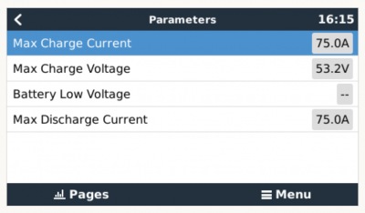
The 'charge current limit' (CCL) as shown in the parameters screen (and received from the BMS, by the GX device, via DVCC) will be the ceiling, and the system will try its best not to exceed that (as much as it can - it may spike under momentary peaking conditions).
This parameters page is also a good place to check that all batteries are connected and working properly. The battery data sheet specifies the normal working conditions, e.g. the current limit per cell. For example, If each battery is rated to 25A charge current, and the menu shows a 75A charge current limit ( 75 / 25 = 3 ) means there are 3 Pylontech battery modules connected.
In off-grid systems, the inverter will prioritise running the load, and potentially exceed this Discharge Current Limit. This could lead to the battery shutting down, and why it is important to follow the minimum battery sizing guide.
In grid connected ESS systems, the inverter will do its best to respect the Discharge Current Limit and use the grid to supplement the load if required.
Note that 'details' menu of the battery (e.g. Lowest and Highest cell voltages etc) is only supported with recent Pylontech firmware.
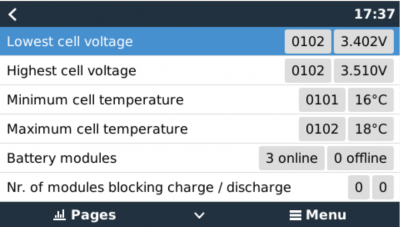
The prefix number to the cell voltages and temperature is used to identify which specific battery in the installation is reporting.
The first two numbers are the group number. The group number is only applied for multiple groups of batteries (with LV-hub), otherwise the group number will always shown as 01.
The second two numbers refer to the battery number, starting with 01, 02…up to 16
The Master battery is located closest on the CAN-bus to the LV-hub, GX device, or group master, and then count sequentially in order from there. Below is a diagram showing the assignments of group and battery numbers:

The firmware requirements for the details menu is documented in the table below.
| Product | Firmware version |
|---|---|
| LV HUB | v1.8 |
| US2000B | v2.9 |
| US2000C & US3000C | v2.1 |
| ForceL | v1.4 |
| US5000 & Pelio-L | All firmware versions |
5. VEConfigure Settings
When using the latest firmware on all compatible connected devices, and once the battery module has been detected by the GX device, battery charging parameters (e.g. Maximum Charge Current, Target Battery Voltage, etc) are automatically configured by the Pylontech BMU, and communicated to the rest of the Victron components in the system via DVCC.
It is possible to override some of these automatic settings to provide additional limitations (e.g. reduce the total charge current that would be provided but the MultiPlus). The following information is provided for that purpose, though is not required for the safe operation of the system.
This section presumes familiarity with VEConfigure software.
Voltages shown are for the 48V model, and should be scaled for the 24V model. The 24V model is an 8-series configuration while the 48V model is a 15-series configuration. Voltages should therefore be scaled by 8/15.
5.1 General tab
- Check the “Enable battery monitor” function
- Set the battery capacity to the total capacity of the battery: eg 50Ah times the number of battery modules for the US2000 model.
- The other parameters (“State of charge when bulk finished” and “Charge efficiency”) can be left to their default setting: They are ignored for a Pylontech installation.
5.2 Charge Settings
Charger tab
| Parameter | Setting |
|---|---|
| Battery type | Lithium |
| Charge curve | Fixed |
| Absorption voltage | 52.0 V |
| Float voltage | 51.0 V |
| Absorption time | 1 Hr |
Note: make sure to double check the float voltage after completing Assistants, and if necessary set it back to 51.0 V.
Note For off-grid use: ignore the 'bms assistant required' warning.
5.3 Inverter Settings
In the Inverter tab of VEConfigure
| VEConfigure Inverter Parameter | Setting |
|---|---|
| DC input low shut-down | 44V |
| DC input low restart | 48V |
| DC input low pre-alarm* | 48V |
* The pre-alarm setting is dependant on your preference and on site specific requirements. You may wish for this to be activated earlier in an off grid situation to allow time to start a backup generator.
ESS System Settings
If you are using the battery as part of a grid connected ESS system, please review the ESS Quickstart guide and Design and Installation Manual.
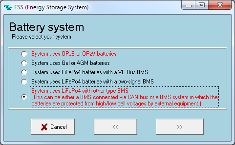
The settings that are specific to the Pylontech battery in the VEConfigure ESS Assistant are below:
Select the externally managed Lithium battery option
| ESS Parameter | Settings |
|---|---|
| Sustain voltage. | 48V |
| Dynamic cut-off values | set all values to 46V. |
| Restart offset: | 1.2V (Default) |
Due to the reliability of the grid supply and the behaviour of the sustain voltage threshold in ESS; you may wish to suppress the low voltage pre-alarm warning so that it does not trigger every day on its regular deep cycle. See ESS FAQ Q5 - about suppressing the low-voltage alarm.
Hardware Protection Points
In normal operation, the charge parameter limits are set by the Pylontech battery and communicated through the system by the GX device to the inverter/charger and MPPT.
- Low Voltage: When the battery discharges to 44.5V or less, battery protection will turn on.
- High Voltage: If charging voltage above 54V, battery protection will turn on.
- Working discharge temperature range is from -10 to 50 degrees celsius.
- Charging temperature range is from 0 to 50 degrees celsius.
- Discharge Current Limit set to 0A at 47V, inverter will turn off.
- Over-charge and Over-discharge Current Limit 102A for 15 seconds, 200A for 0.1 seconds and 400A short circuit current.
If operation is attempted outside the operating range, the battery will disconnect to protect itself.
6. VE.Direct MPPT Settings
In normal operation the MPPT charge characteristics are governed by the GX device via DVCC, with instructions from the connected Pylontech battery.
This section presumes familiarity with VictronConnect
The settings below can be set as a precautionary measure.
| MPPT Parameter | Setting |
|---|---|
| Battery voltage. | 48V |
| Absorption voltage | 52V |
Note for MPPT RS - the Remote Mode in VictronConnect must be set to Remote on/off, not BMS.
7. Example Wiring Diagram
8. Troubleshooting
If the system is not operating correctly, go through these steps.
Step 0. If the Inverter/Charger or GX device does not switch on
When the grid is connected there are two software controls to sustain voltage. The Minimum SOC (while grid is connected) set in the GX device, and the sustain voltage (set in the ESS assistant).
If the grid fails and no AC supply is available, in this deeply discharged state, and the battery has set the Discharge Current Limit (DCL) to 0A, then the inverter will turn off in a software off state. The GX device will remain on, as there is still DC voltage provided by the batteries for a while.
Note in this state an AC PV inverter will not produce any power, and will not start up, as it requires the inverter to create the sine wave to synchronise.
If the AC grid or generator, or DC MPPT is connected, then the battery will begin to charge and then the inverter will start itself again automatically, also resuming charge from an AC PV inverter.
If instead the battery becomes completely discharged the battery will further protect itself by not just sending the 0A discharge limit, but also disconnecting DC voltage from the battery terminals (via internal MOSFETS). As there is no DC voltage available on the terminals any more the GX device will also shut down, and the inverter will also then be hard off (not just software off).
If you then reconnect a DC charge source, or AC input supply (grid or generator), after approximately 2 minutes the inverter will start up again, power the DC bus, powering up the GX device, and then powering up the battery, and the system will recover.
Step 1. Check that the Pylontech battery is visible on the GX device list
If its not visible, check:
- GX device firmware version (update to latest version, v2.15 or later)
- CAN-bus communication cabling between Pylontech and Victron system. Make sure that it is in the right way around.
- Pylontech system is up and running (LEDs are on)
Step 2. Check that the Pylontech battery is ready for use
Check the Max Charge Voltage parameter. This voltage parameter is sent, together with the other three parameters, by the Pylontech system via the CAN-bus cable. They are visible on the GX device: Device List → Pylontech battery → Parameters menu.
Step 3. Check the Pylontech manual
The Pylontech manual contains additional diagnostic and troubleshooting information, specifically around decoding any indicator LEDs.
9. FAQ and Known Issues
The maximum charge and discharge current is limited to 25A, but the data sheet tells me the maximum is 100A.
The maximum current is limited to keep the battery healthy and reach the 10 year guarantee. In off-grid, the inverter can draw more than the 25A limit to run the loads, make sure you have sufficient batteries installed to keep the load per battery around this limit.
After charging the battery the charge current often changes between 0A and 25A.
This is caused by cell balancing inside the battery. This happens with new batteries and after a deep discharge.
My system isn't charging at the rated capacity, or my PV is shutting down
Pylontech's BMS will restrict the Charge Current Limit of the battery in cold weather. The precise temperatures and limits are not published by Pylontech, but anecdotally from reports on Victron Community it would appear that batteries begin to be limited below 18 degree C, severely limited below 10 degrees C, and completely restricted from charging below 2 degrees C.
You can confirm if this is affecting your installation be entering the Pylontech Battery menu on your GX device, and then the Parameters Menu. This will report the Charge Current Limit (CCL) and Discharge Current Limit (DCL). This information is also logged in the advanced section of the VRM monitoring portal.
My system only charges the battery to 52.4V
When DVCC is enabled, the battery (via the CAN-bms) is responsible for the charge voltage. The Pylontech battery requests a charge voltage of 53.2V. We have however found that in practice this is too high.
The Pylontech battery has 15 cells in series, so 53.2V equates to 3.55V per cell. This is very highly charged and makes the system prone to go overvoltage.
It should also be noted that a LiFePO4 cell stores very little additional energy above 3.45V.
For this reason we opted to override the BMS and cap the voltage at 52.4V. This sacrifices almost none of the capacity and greatly improves the stability of the system.
The battery won't charge to 100%
Also see the question above. The state of charge of the battery is estimated based on the overall voltage and on how well balanced the internal cells are. Because we cap the battery voltage at 52.4V, the state of charge will sometimes rise very slowly once it reaches the mid-90s. This is normal and usually resolves over time.
'Internal Error' shown on battery status
The 'Internal Error' shown in battery status is not a critical error. This only defines that within a battery system, some of the slave batteries are offline(which is due to these modules have been discharged to an extremely low SOC or being in idle mode for more than 72hrs), once the system is available for a charging activity such an error will be automatically eliminated.
'High cell voltage' warning or alarm shown on battery status
The 'high cell voltage' warning or alarm is not unusual on new batteries that are not yet balanced. To help the batteries balance quickly, keep the batteries fully charged until the errors go away. In an ESS system, set it to 'keep batteries charged', in an off-grid system the fastest way is to either charge / balance the battery before installation, or to fully charge with a generator if not enough solar is available to keep the batteries fully charged.
If you are unable to maintain the target voltage to balance the batteries without the 'high cell voltage' alarm occurring, you may need to enable and set the “Limit managed battery charge voltage” setting in the DVCC menu of the GX device. Reduce this voltage as necessary until the alarm stops. After sufficient time to balance the batteries, try increasing this value until it can be disabled again for normal operation.

If it is not possible to raise the voltage over time, and eventually disable this manual override:
1: If you have 2 or more batteries in your system, you can try shutting down the system once it is as close to fully charged as possible, and then physically connecting the batteries in smaller groups (or even individually) so that balancing can occur on each individual battery without it being masked by the others connected in parallel. It may help you to see the indicator lights on the battery (if available on that model) to find which battery might be out of balance with the others.
2: Contact your Pylontech dealer for further assistance (they can provide additional software to see individual cell level data), or assist with other potential solutions.
10. Further Information
For information about where to buy or find suitably qualified installers, visit the Where to Buy Page.
Further community discussion about installing and using Pylontech and Victron can found at Victron Community, use the topic label 'Pylontech'.
LV-Hub specific information
Please discuss large Pylontech systems that require the LV-Hub with your experienced Pylontech agent FIRST. These additional LV-Hub references are provided without any support or endorsement from Victron, and should not be assumed to be up to date. Defer to your experienced dealers recommendations.
Victron Community discussion on LV-hub configuration settings with Victron
DISQUS
~~DISQUS~~