Add this page to your book
  Remove this page from your book
  Manage book (
 Help
Help This is an old revision of the document!
Table of Contents
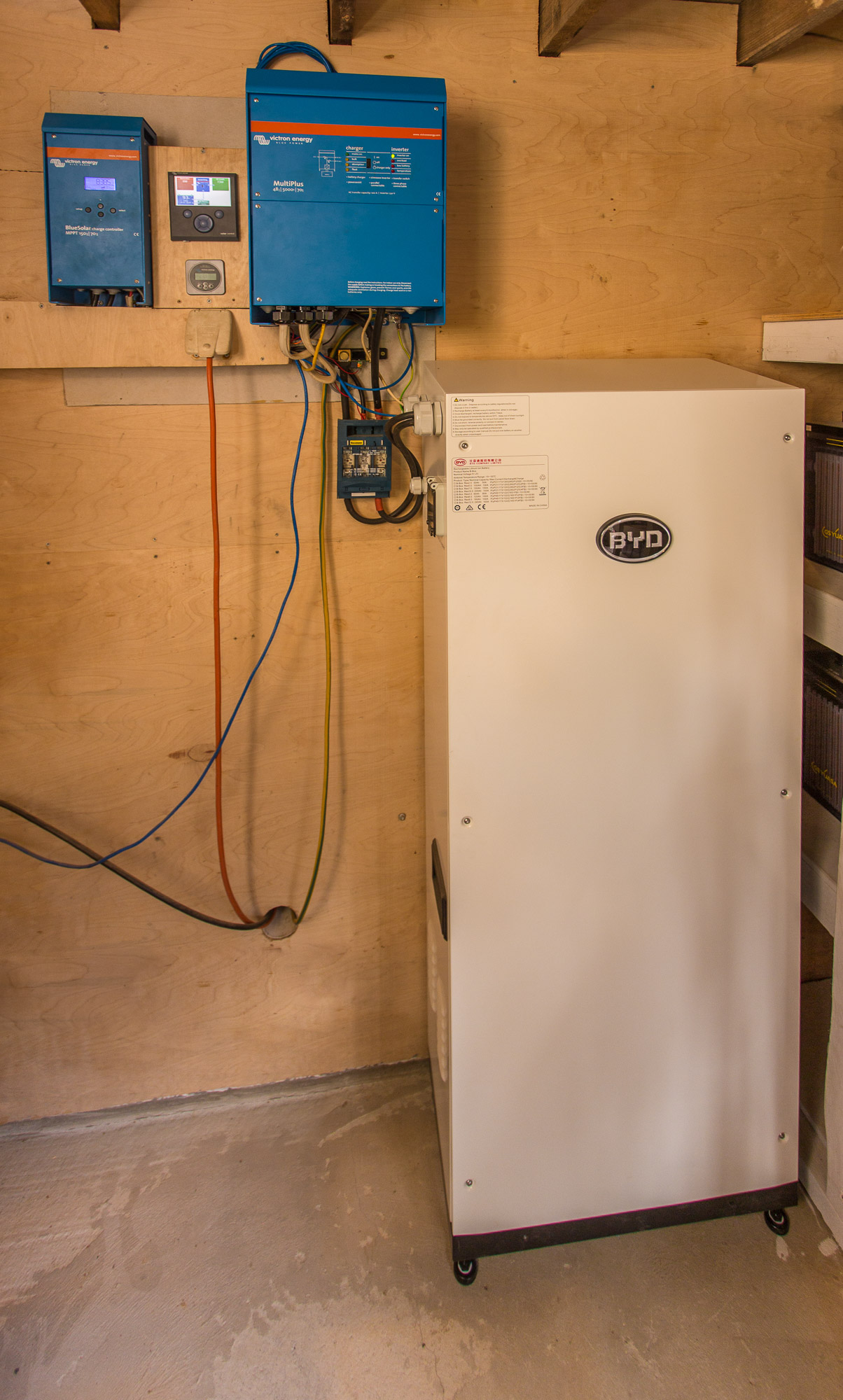
Offgrid BYD on Victron install guide
Installation guide and basic review for BYD B-Box Res IP55 with 4×2.5kWh batteries on Victron off-grid system
Guide by: Oliver Holmgren & Guy Stewart

Disclaimer: No warranty of the accuracy or completeness of the information in this document is given. Any qualified or otherwise party who chooses to use this document and the information contained does so at their own discretion and risk. The authors of this document are in no way liable for the use or misuse of this information.
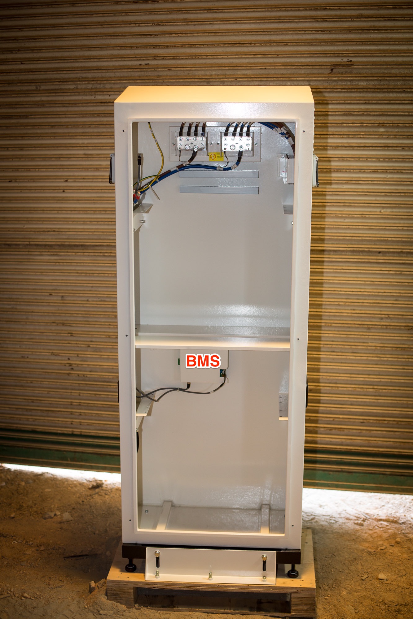
Cabinet, breakers and cables
Packaging seemed solid enough and indicates that this is Version 1.1. There were no damage or marks to paint or otherwise.
There was no installation manual or warranty documentation included. Also see BYD installation video.
The cabinet seems decently made. External edges are smooth. The access panel (not door) is screwed on with six button head cap screws (also called allen key or hex key bolts).
BYD B-Box IP55 Cabinet V1.1
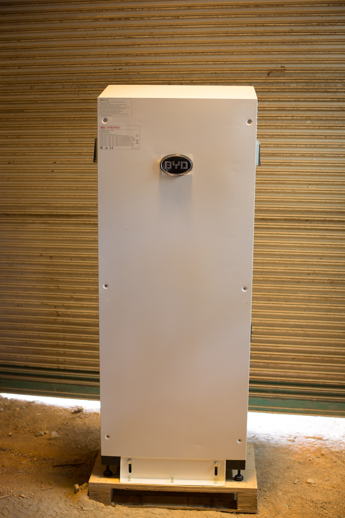
There is a foam seal all the way around the panel that should seal reasonably well when screwed on. The screws bound in their threads a little. Some remains of metal particles in the threads seemed to be the cause. The second unit we installed actually had one screw seize in the thread and needed cutting off and drilling out. There are handles on the side for lifting. There are air vents on the top right and bottom left. They are screened with a fine metal mesh and have filter foam on the inside. However the filter foam wasn’t perfectly flat. Might need adhering to work properly. Given there isn’t much air flow in the box I can’t imagine this will be an issue. The main thing I was worried about was sharp edges inside the cabinet that would make installation an issue but all the edges seemed finished reasonably well. No cuts or scrapes on hands after the install.
There is an electrical wiring diagram on the inside of the access panel.
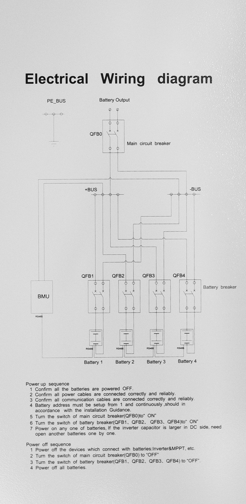
There are four individual breakers (one per battery unit) that are externally switchable and one main breaker (also externally switchable).
Both breaker blocks must be unbolted to get to the clamp screws for installing the remaining cables. The battery cables supplied with each battery are lugged on both ends. The lugs are of different sizes. Ensure you select the correct lug size for the battery end and the larger end for the breaker block as you will have to cut the lugs off at the breaker block end. Little lightweight cable end crimps are supplied that are soft enough to conform when screwed down in the breaker blocks.
Caution: ensure you seat and firmly tighten the cables in the breaker blocks.
I tightened the screws and then wiggled the cables and then check the cables couldn’t move in the breaker blocks. Reason being is its very hard to get to the screws to tighten the breaker block clamps after all the batteries are installed in the cabinet. Obviously also be careful as the breaker blocks could…break, if over tightened.
Because the cabinet can have 1, 2, 3 or 4 batteries installed, quite a lot of cabling still need installing. This may be a downside for installers given the time it takes to get it all in place compared to a pre built unit.
There are nice cable management channels however there are metal screws that hold them on that stick up.
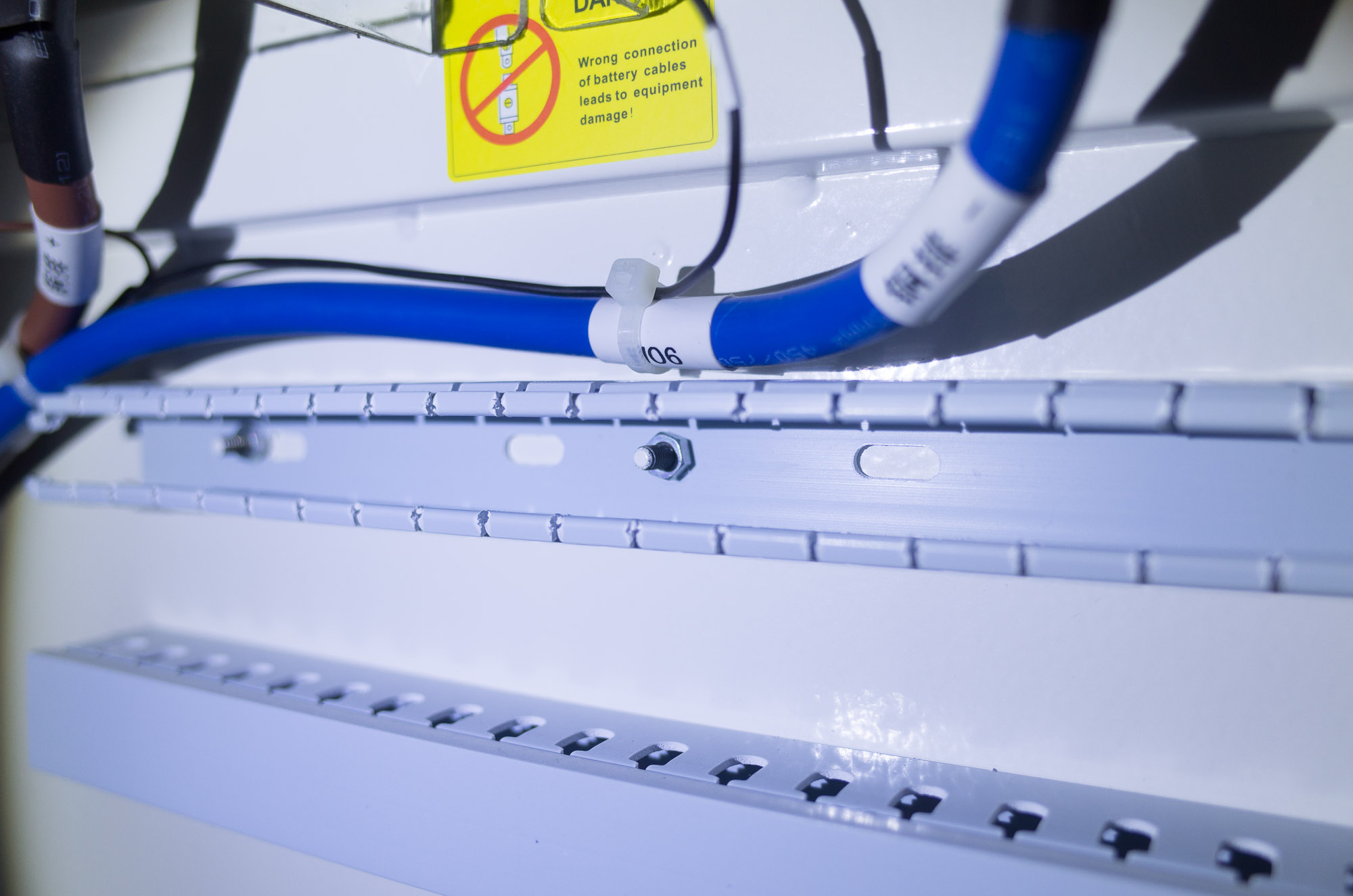
This seems really bad design as there is the possibility that the metal screws could damage the single insulated battery cables.
Power cables
I have mentioned a bit about this earlier. Basically, I cut the bigger lugs off the power cables and crimped the soft crimps onto the fresh ends and installed them into the four way breaker block.
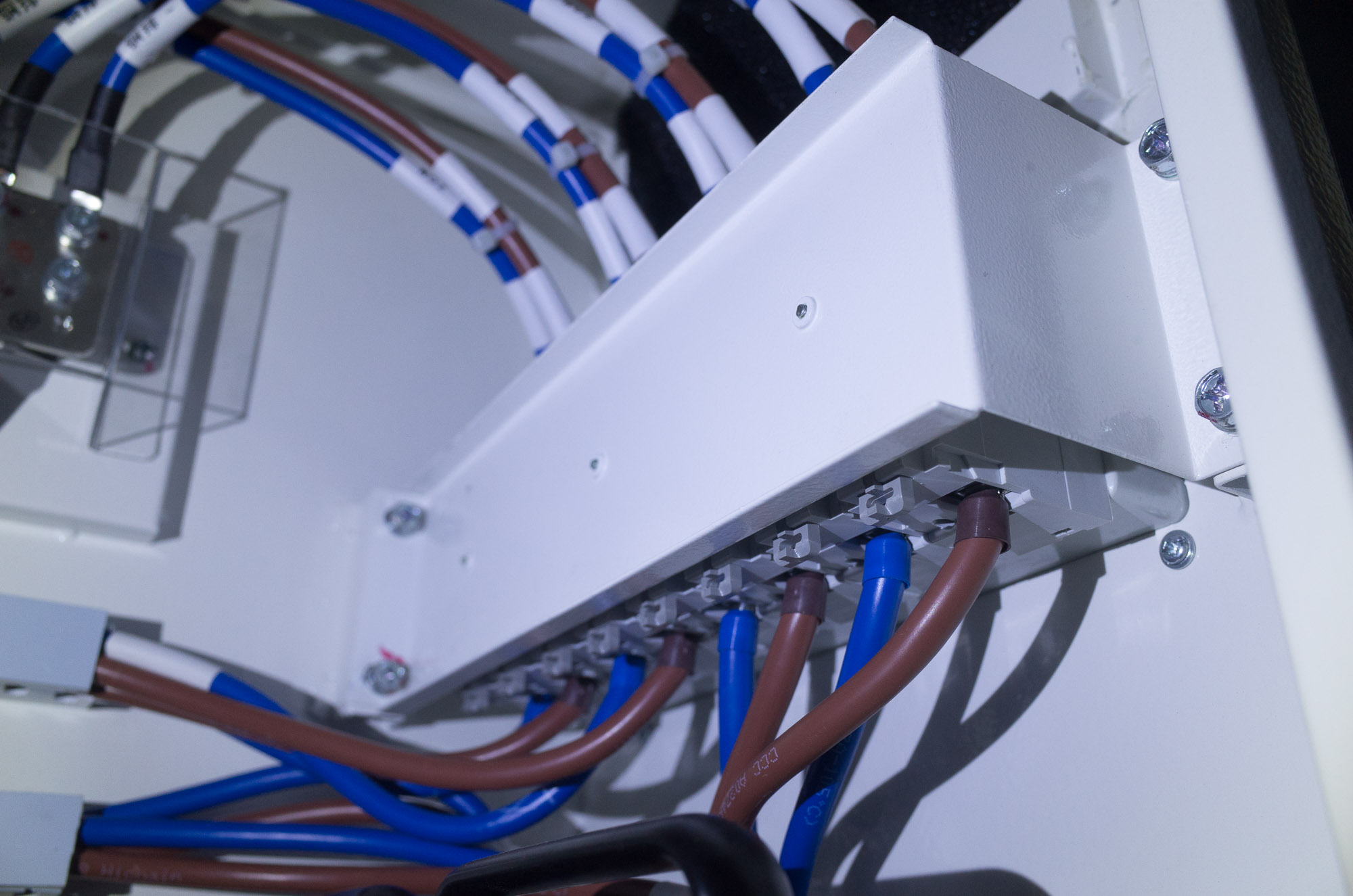 I then routed the cables (through the bad cable management channels). Two sets to the top and two set to the bottom. I did notice the positive cables were longer. Not sure why. It would be possible to cut the cables for the top two batteries shorter but I didn’t as it will marginally decrease the resistance of those two batteries, especially under high loads. Maybe it’s doesn’t matter but I left them equal.
The BYD manual says to test the battery voltage. Considering the batteries are all still off at this stage I am not sure why. Voltage was 12.2v on all batteries. I was surprised to see any voltage at all.
I then routed the cables (through the bad cable management channels). Two sets to the top and two set to the bottom. I did notice the positive cables were longer. Not sure why. It would be possible to cut the cables for the top two batteries shorter but I didn’t as it will marginally decrease the resistance of those two batteries, especially under high loads. Maybe it’s doesn’t matter but I left them equal.
The BYD manual says to test the battery voltage. Considering the batteries are all still off at this stage I am not sure why. Voltage was 12.2v on all batteries. I was surprised to see any voltage at all.
Connect the output side of the BYD main breaker (internal to the cabinet) to the DC breaker and fuse assembly of the system(external and separate to the BYD cabinet).
BMS and internal coms cabling
The Battery Management System(BMS) is in the bottom section of the cabinet.
 It has a CAN bus RJ45 port on the left hand side, which is labeled, that connects to the CAN bus port on the Color Control GX (CCGX) or Venus GX. The BMS layout, colour and port configuration differed from the installation manual. Victron call the CAN port VE.CAN on their products. The Victron CAN bus and BYD CAN bus protocols are a bit different. As such it is only possible to use one or other of the communication methods on a single CAN bus. It is important to understand here that a CAN bus can have many ports but they are all on the one bus. In this case the CCGX has two CAN ports but they are on the one bus. The Venus GX has one CAN bus at this time however it has the hardware for a second CAN bus that may be enabled at some stage. At this time it is not possible to plug in both the BYD battery AND other Victron VE.CAN products at the same time. There are settings in the CCGX that allow you to switch between the CAN bus protocols. This is not an issue for users who have no VE.CAN devices. For new installs it is recommended to use VE.Direct MPPTs where possible. In my case, the MPPT uses VE.CAN and as such I am unable to have it connected. This means I am unable to monitor or log solar yield data.
There is another RJ45 connector on the BMS that is not labeled. It has a cable plugged into it that goes to the top of the cabinet. If I had been installing 1 or 2 batteries the cable could have stayed plugged in. To install 3 or 4 batteries, take it out. This port is the main “COMout” that should connect to the first battery Management Unit (BMU) on the first battery.
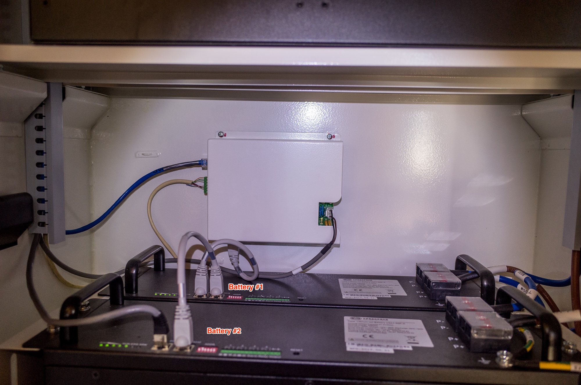
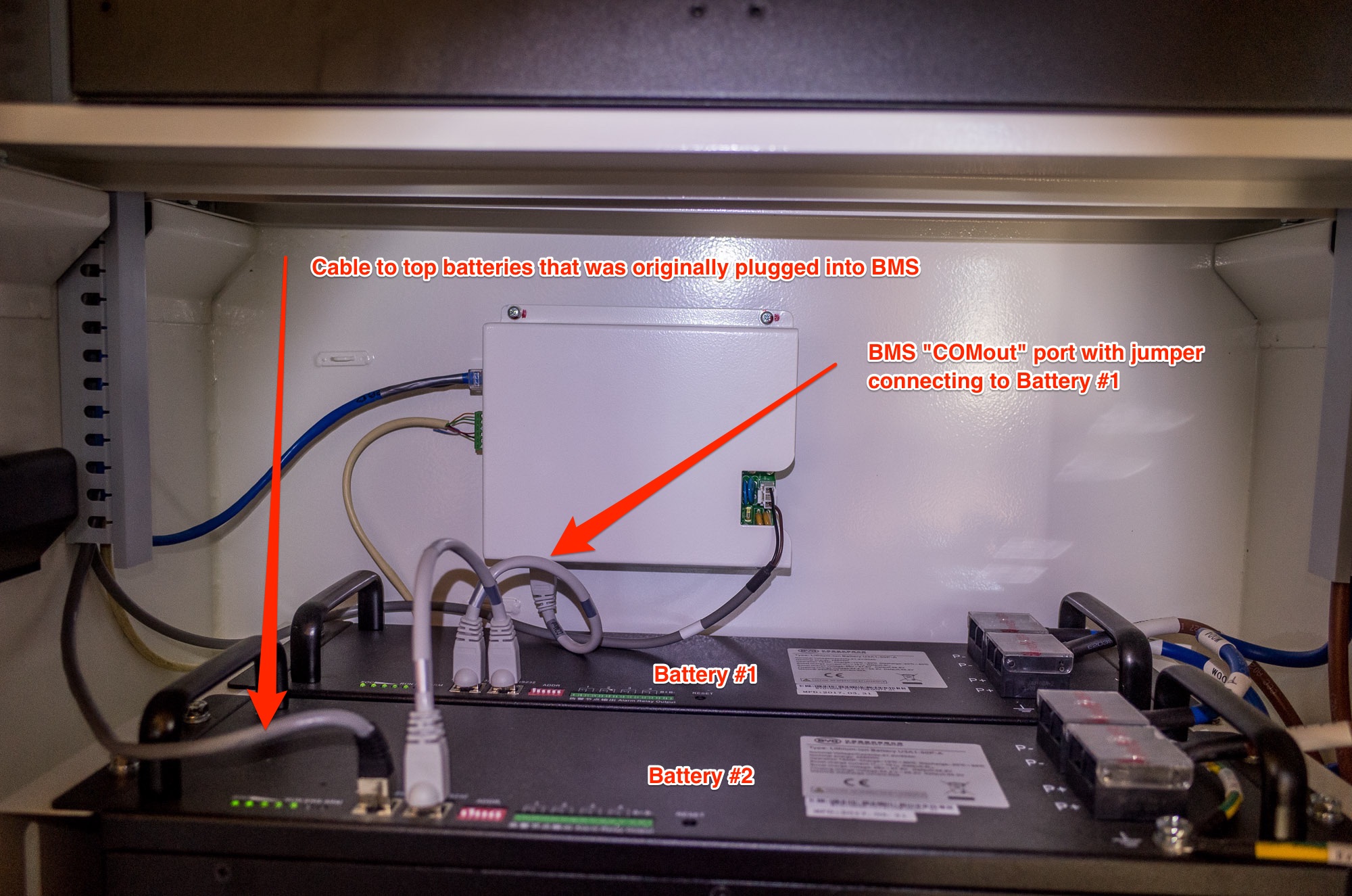 The little ethernet jumper cables intended for connecting the BMUs together are labeled with COMin and COMout ends. Because one comes in every battery box, there was one left over. I put the COMout end of the first ethernet jumper cable into the bottom unlabeled port of the BMS and the other end into the left RJ45 port of battery #1. I then put the COMout end of the second jumper into the right RJ45 port of Battery #1 and put the COMin end into the RIGHT port of the battery #2. I did that just because that’s the way BYD did it.
I then put the unlabelled ethernet cable that was originally plugged into the BMS into the left RJ45 port on battery #2.
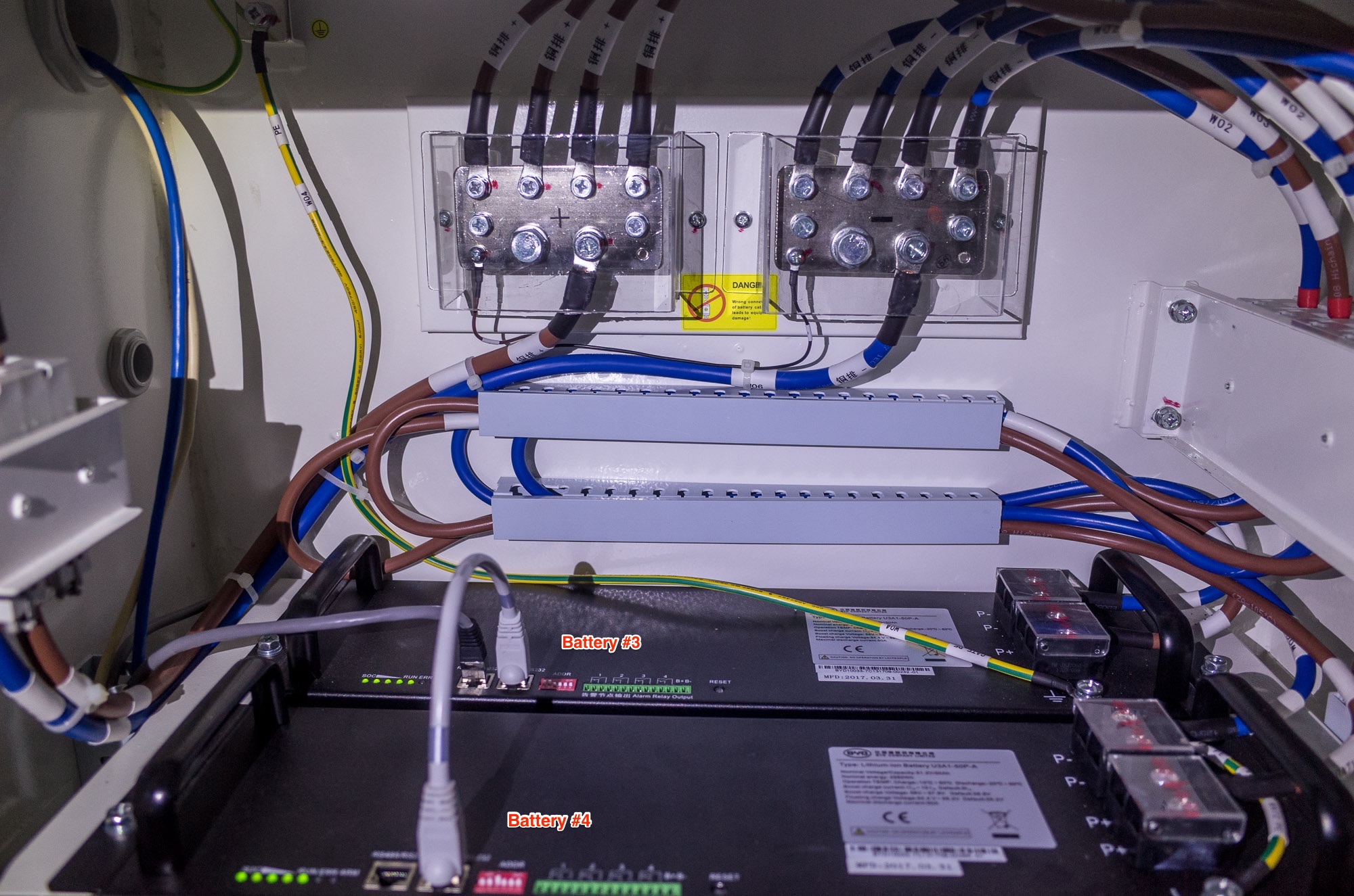 The top end of the cable went into the left port of battery#3. Finally the COMout of the third jumper went into the right port of battery #3 and the COMin went into the right port of battery #4.
BMS to CCGX (or Venus GX) cabling
A custom ethernet cable is required to to connect the BYD BMS to a Victron CCGX. Venus GX installers/users are recommended by Victron to follow the same procedure. Victron are yet to support the second CAN bus on the Venus GX however it is possible to enable and use the second CANbus on the Venus GX now using this guide we just wrote. Thanks to Victron and Rainbow Power Company for their input.
Custom Cable pinout
| Function | VE.Can RJ-45 | B-Box RJ-45 |
|---|---|---|
| GND | Pin 3 | Pin 2 |
| CAN-L | Pin 8 | Pin 5 |
| CAN-H | Pin 7 | Pin 4 |
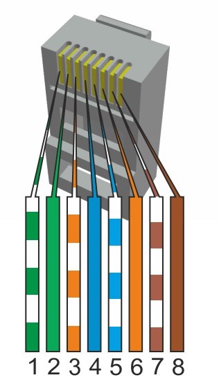
For reference here’s an ethernet plug diagram. Be aware that some ethernet cables may vary.
 How you make up you custom ethernet cable is up to you but to do it properly you should use a proper crimper and fresh RJ45 male connectors.
Label both ends of the cable and install it.
How you make up you custom ethernet cable is up to you but to do it properly you should use a proper crimper and fresh RJ45 male connectors.
Label both ends of the cable and install it.
Battery addressing
The batteries need to be addressed with the “ADDR” jumper blocks.

Be aware that the numbering system is binary. Down is 0 and up is 1. The numbers under the jumper block indicate the number of the jumper.
Battery jump block config from manual
| Battery # | Address | eg |
|---|---|---|
| 1 | 100000 | First jumper up, all the rest down |
| 2 | 010000 | Second jumper up, all the rest down |
| 3 | 110000 | First two jumpers up, all the rest down |
| 4 | 001000 | Third jumper up, all the rest down |
Top two batteries.
 The bottom two batteries.
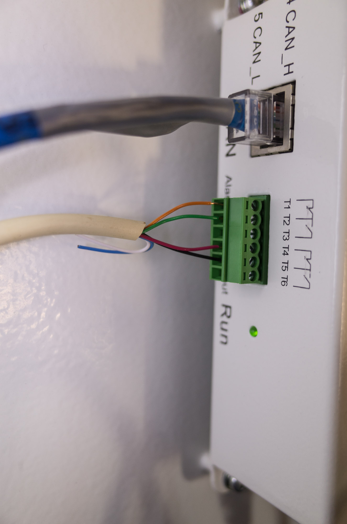
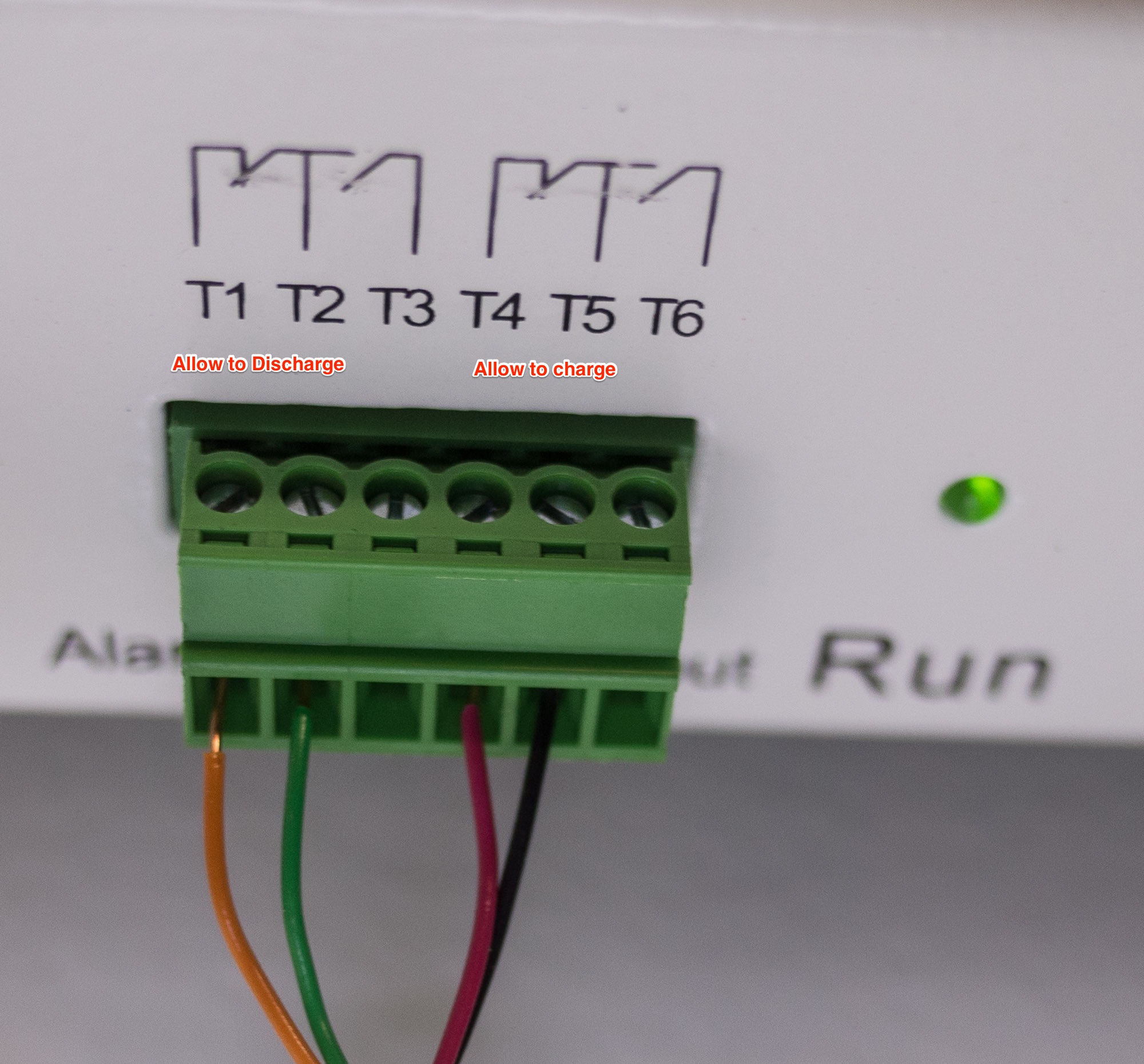
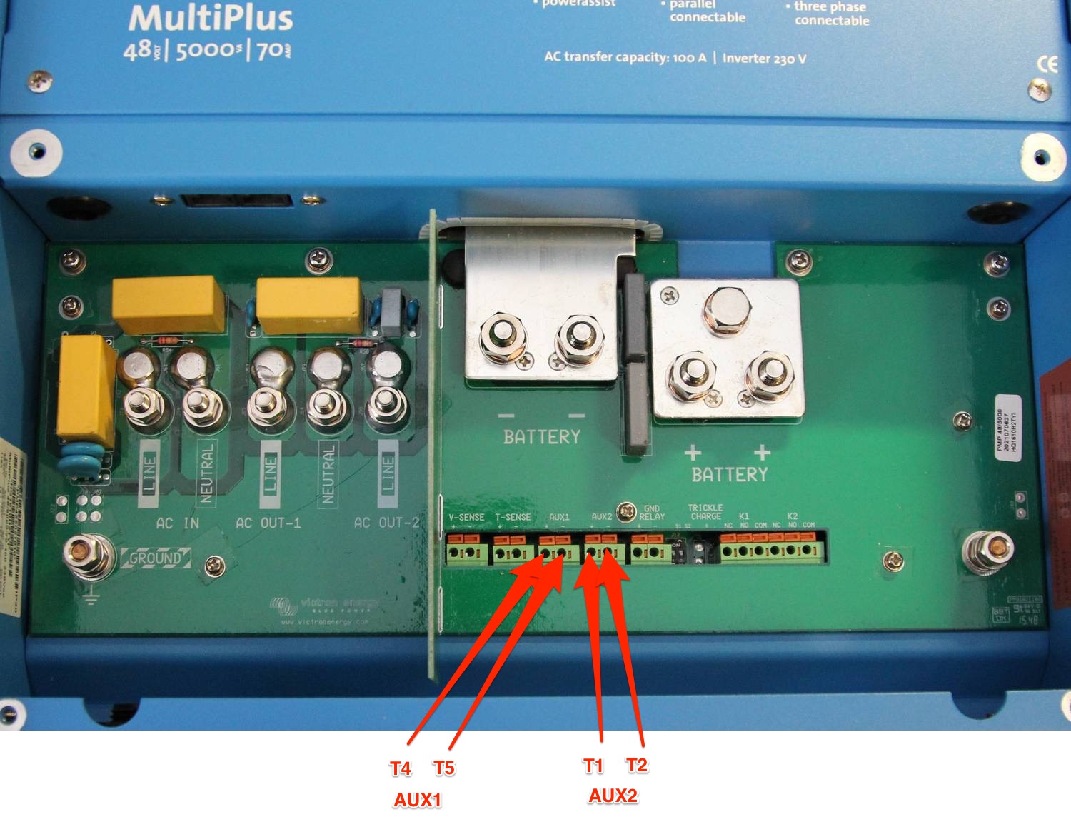
BMS to Multi/Quatro communications wiring
We need to wire the allow to charge and allow to discharge relays on the BMS to the Multi/Quatro.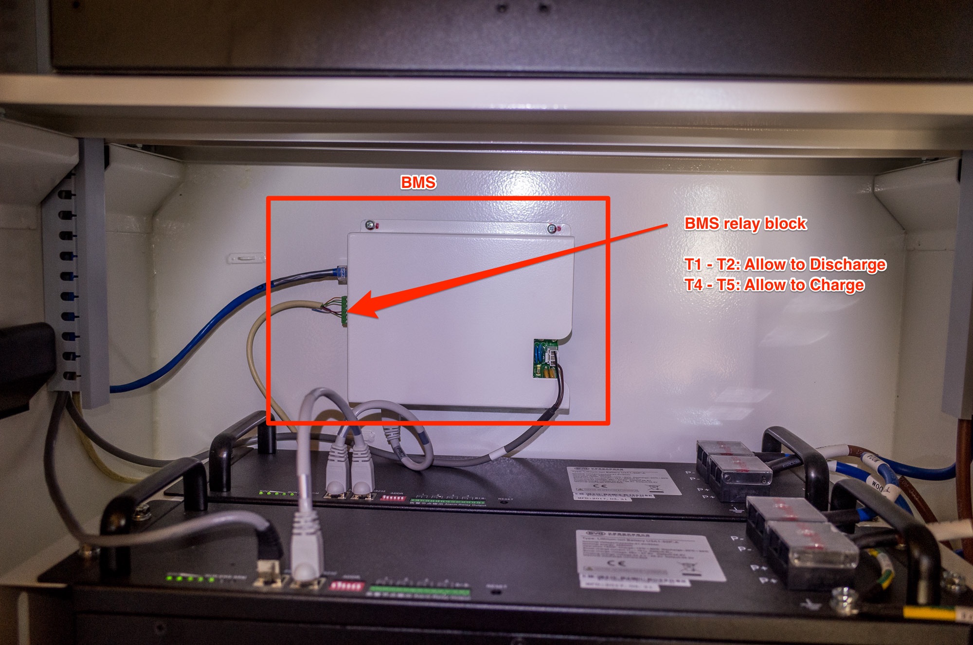
Inverter/Charger (Multiplus, Quatro etc) firmware and settings
Updating firmware for Victron VE.BUS products is not recommended for end users. I don’t think there will be many end users doing all this anyway but do heed Victron’s warnings about this procedure. It’s complicated!
If you already have a power source, you can and should configure all the required settings first. We had a functioning lead acid bank to operate off while setting everything up. If you don’t then this whole procedure may vary a little. This is important to consider as the BYD battery may turn itself off without a correctly configured connection to the CCGX/Venus GX which sends the signal for it to “stay alive”. If the battery turned off midway through a firmware update the consequences could be serious. If the connection between the CCGX/Venus GX and the BYD is established first, the battery will continue to operate. If you plan to use the BYD to power the inverter/charger for the firmware update process, first ensure the battery is connecting to the CCGX/Venus GX and wait ten minutes to ensure its all operating correctly. Setting up the Lynx Ion BMS Support Assistant can be done second.
My Inverter/Charger is a Multiplus 48v, 5000VA with a new (larger chip) which is a model 2624 that came with Firmware version 155 so the full number printed on the circuit board was 2624155. My latest firmware was 413.
See victron documentation for selecting the correct firmware.
See victron documentation for updating firmware.
Log into your Victron Professional account and download appropriate firmware that supports the Lynx Ion BMS Support Assistant. You will need:
- USB to MK2 or MK3 cable
- The latest versions of USBMK2 Drivers, VE Configure Tools & VE Power Setup which are all available on the software section of Victron’s support & downloads page.
- A laptop running Windows (with a good battery and fully charged)
Setup the Lynx Ion BMS Support Assistant (credit:Victron BYD integration page).
Connect the laptop to the Inverter/Charger with the USB adapter, and open the VEConfigure app.
You may need to disable the Virtual Switch to enable the “Assistants” functionality.
Install the “Lynx Ion BMS support Assistant”:
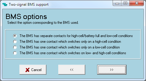
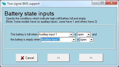
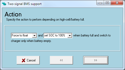 This assistant will be configured using VE Configure.
This can be done directly if you are connected to the Multi/Quatro with the USB to MK2/mk3 cable. If you are connected through the CCGX/Venus GX you will need to pull the settings with VE Power Setup, open and edit them with VE Configure and then put them with VE Power Setup again.
If you already have a firmware that supports the assistant you can just use the CCGX or Venus GX to get and put the settings on the Multi/Quatro. See Victron’s documentation on this procedure.
Use VE Configure to set charge parameters
Victron BYD integration page suggests these settings.
| Parameter | Setting |
|---|---|
| Battery Type | Lithium |
| Charge Curve | Fixed |
| Absorption Voltage | 56.3V |
| Float Voltage | 56.2V |
| Absorption Time | 1 HR |
The specifications on the battery units themselves.

We contacted Victron about the discrepancy. The official reply was: The settings given in our instructions are the correct settings. These have been checked and verified by BYD themselves. Area Manager Oceania Victron Energy BV.

Important note: As of 28/06/2017, users who have the Victron VE.CAN MPPT solar charges will NOT be able connect them to the CCGX CAN bus at the same time as the BYD BMS. Considering the BYD BMS must be connected, it is not possible to monitor and manage the MPPT via VE.CAN. The Venus GX has a second CAN bus but IS NOT officially functional at this time. See this guide for activating the second CANbus on the Venus GX.
For those users that have Victron VE.Direct MPPT solar chargers, the charges should connect and operate as usual.
Configure VE.CAN MPPT
I had already updated firmware to 2.05. If you haven’t, use the remote update procedure through the CCGX and the VRM to do it to save the need for the very expensive USB to VE.CAN cable. Set the charge profile to #8 (user configurable). Do not set it to Lithium! That setting is for Victron lithium and is not appropriate.
Again, set the charge parameters as follows
| Parameter | Setting |
|---|---|
| Absorption Voltage | 56.3V |
| Float Voltage | 56.2V |
| Absorption Time | 1 HR |
Ensure you turn down the max absorption time to 1 hour.
For those with VE.CAN MPPTs, there was an update to the hardware in 2014 adding the Remote On/Off hardware. The Remote On/Off function talked about on the Victron BYD integration page may only be configured on those later models. I was able to get a fully operational system without it. We are waiting on clarification but it appears it is only required for grid interactive systems that use the BYD battery with VE.CAN MPPTs.
This is not an issue with the VE.Direct MPPTs.
Startup procedure
The procedures in the BYD manual do not make sense. They call for operations to occur on the CCGX before there is power to it. And ask for the battery to be set to DOD 5%. I was not able to see these settings. Perhaps the manual is out of date.
The following operations worked fully.
Pre-startup check:
- Ensure all batteries are off. There should not be any lights showing on the batteries.
- Ensure solar breaker is open (off)
- Solar Charger will be off as there is no power yet and breaker is off. There is no hardware switch.
- Ensure the inverter/charger switch is off.
- Ensure DC breaker and fuse assembly is open (off).
- Ensure Main BYD breaker is open (off).
- Ensure all four battery breaks are open (off).
- Ensure all cables are firmly seated and attached properly.
- Ensure all coms cables are seated and attached properly.
- Take all reasonable and legal measures required.
- Ensure all settings in the Multi/Quatro, the solar charger and the CCGX/Venus GX are programed correctly (yes, this requires an operating battery other than the BYD).
Startup procedure:
- Start Battery #1 by holding the reset button down for 1 second. The lights on the left should come on.

- Repeat the procedure for the remaining batteries
- Close (turn on) the individual battery breakers.
- Close (turn on) the main DC breaker and fuse assembly (external to the BYD battery).
- Ensure all settings in both are ready.
- Configure the CAN bus on the CCGX for communication with the BYD BMS. At the time of writing (CCGX Candidate firmware version 2.07) there were options in the CCGX for operating the can bus at 500kbaud rate which is whats required for communication with the BYD BMS.
 CCGX–>Settings–>Services–>CAN-Bus BMS(500kbaud)
- Turn on Multi/Quatro. If it does not come on after the usual warm up period, something isn’t right.
- Close (turn on) the main solar breaker
- Enable charging on the MPPT
Finally, keep an eye on all the parameters while the battery is charging.
Hopefully this info has been helpful.