8. Troubleshooting
Refer to this chapter for addressing any unforeseen behaviour of the solar charger. Start by reviewing the common issues listed here during troubleshooting.
If the problem persists or requires technical assistance, contact the point of purchase – the Victron Energy dealer or distributor. If unsure whom to reach or unaware of the point of purchase, visit the Victron Energy Support webpage for guidance.
8.1. Solar charger is damaged
Before proceeding with troubleshooting, it is important to inspect the solar charger for any visible damage. Please note that damage to the solar charger is typically not covered by warranty.
By conducting this initial visual inspection, you can identify any visible damage that may impact the functionality of the solar charger:
Visual inspection | |
|---|---|
Step 1 | Examine the solar charger for any signs of mechanical damage to the housing or electrical terminals. Please be aware that this type of damage is not covered by warranty. |
Step 2 | Inspect the electrical terminals of the solar charger for signs of burning or melting. This type of damage is often caused by loose electrical connections, the use of rigid core cables, or exceeding the MC4 terminal current ratings. Please be aware that this damage is not covered by warranty. Refer to chapter PV connections burned or melted for more information. |
Step 3 | Look for any indications of water damage or corrosion on the solar charger, especially around the electrical connection area. It is important to note that such damage is not covered by warranty. |
8.2. Solar charger is unresponsive
If the solar charger is unresponsive, it means that none of its LEDs will illuminate or blink, there is no charging activity, and it is unable to establish communication with the VictronConnect app through the VE.Direct port.
Conversely, if the solar charger is active, you will notice its LEDs are either illuminated or blinking, and it can successfully communicate with the VictronConnect app via the VE.Direct port.
The solar charger should activate as soon it receives power from the battery, the PV supply, or both. Note that the solar charger does not have an on/off switch.
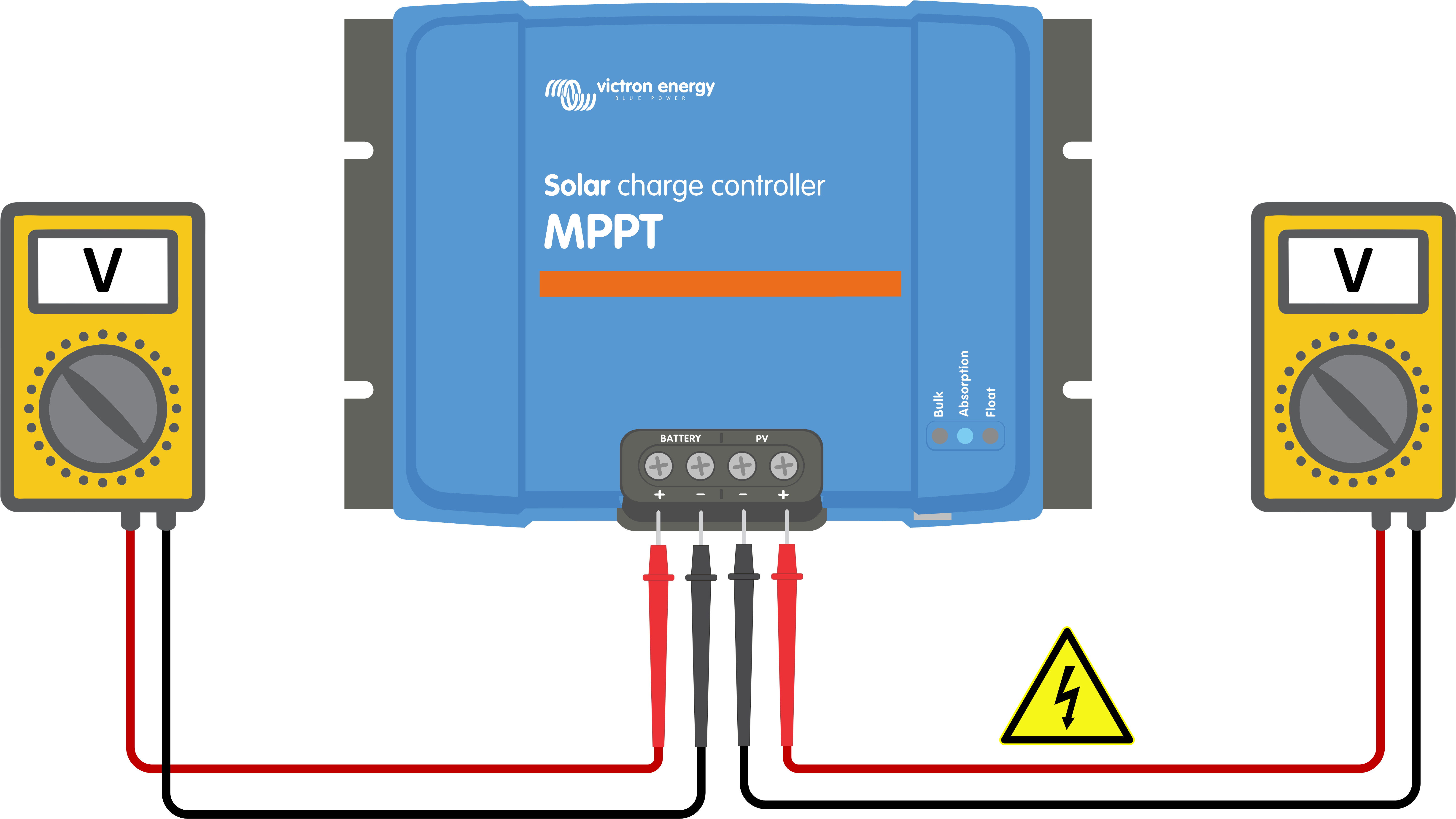
To troubleshoot, verify that the solar charger is receiving either battery or PV power, using the below procedure.
Unresponsive solar charger troubleshooting procedure | ||
|---|---|---|
Step 1 | Set a multimeter to DC voltage mode. | |
Step 2 |
WarningWARNING: Certain solar charger models may have PV voltages up to 250Vdc. Voltages exceeding 50V are generally considered dangerous. Only a qualified technician should handle dangerous voltages. | |
Step 3 | If the battery or PV voltage is below the minimum voltage, check the following:
| |
Step 4 | If, even after confirming sufficient battery or PV voltage, the solar charger remains unresponsive, consider the solar charger to be faulty. | |
8.3. Solar charger is off
When the solar charger is off, the VictronConnect app shows this on the status screen. Click the "Why is the charger off?" text for a pop-up window with an explanation and possible remedies.
There is insufficient PV power. Refer to the PV voltage too low subchapter.
The settings are being edited on an external display. Refer to the Settings being edited on an external display subchapter.
The charger is disabled in the settings. Refer to the Disabled in the settings subchapter.
The charger is disabled by remote or BMS. Refer to the Disabled by remote or BMS subchapter.
Low lithium battery temperature. Refer to the Low lithium battery temperature subchapter.
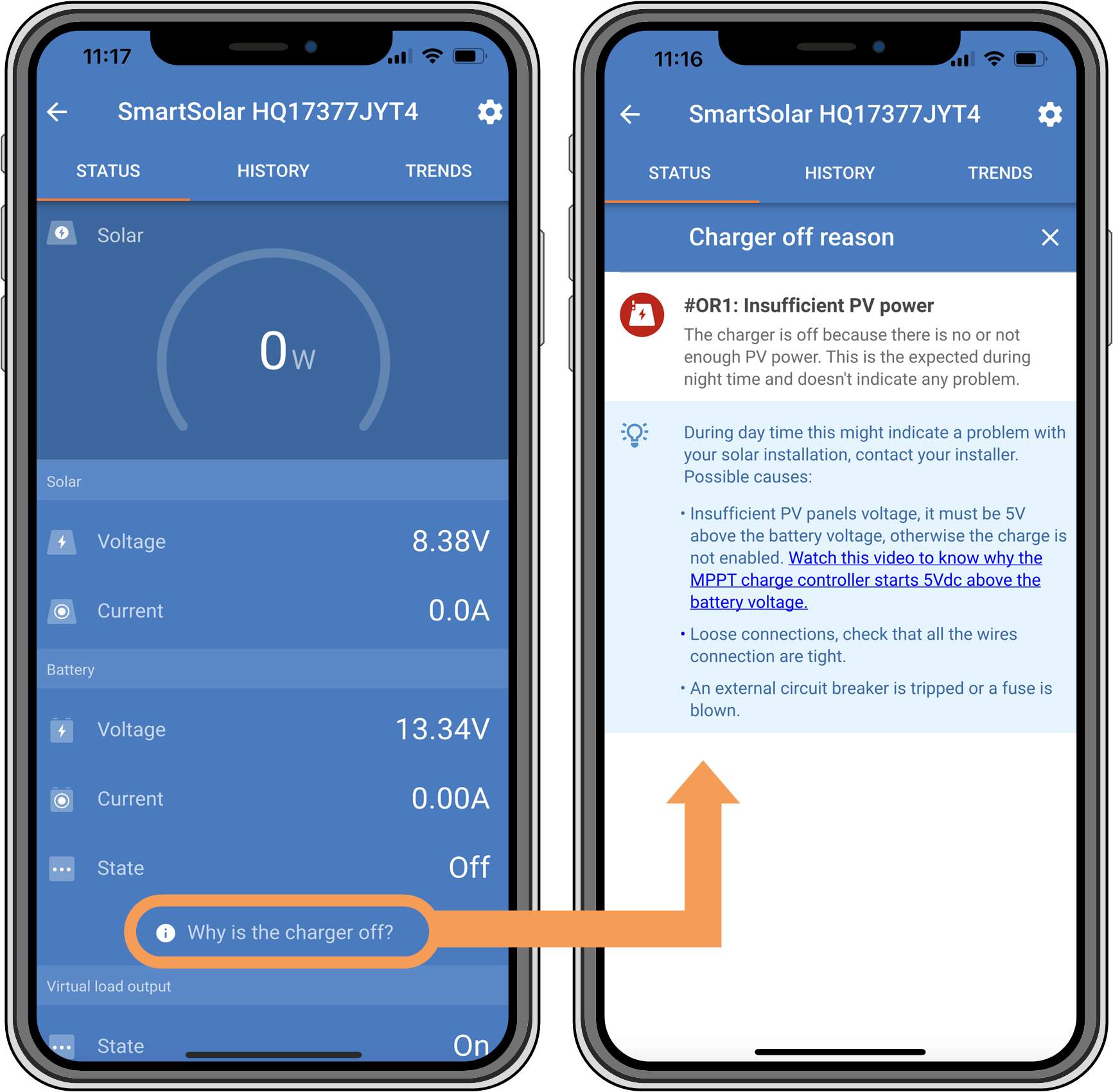 |
VictronConnect app – Why is the charger off?
8.3.1. PV voltage too low
The solar charger starts charging when the PV voltage is 5V above the battery voltage. Charging continues if the PV voltage remains 1V higher than the battery voltage.
To troubleshoot if a low PV voltage is the reason the solar charger is not charging, use the below procedure.
PV and battery voltage check | ||
|---|---|---|
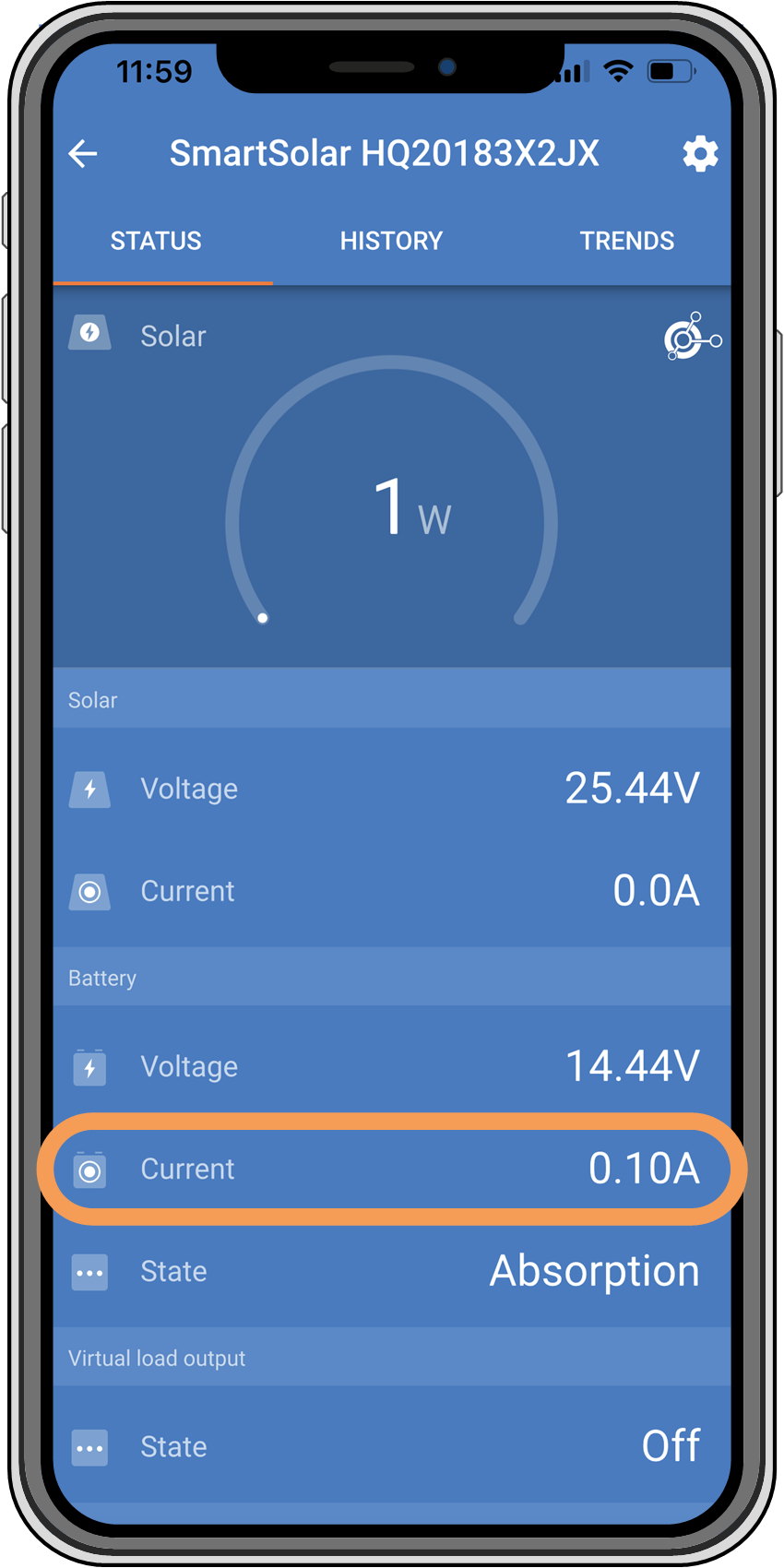
Step 1 | Use the VictronConnect app, a solar charger display or a GX device to check the battery and PV voltage.
| |
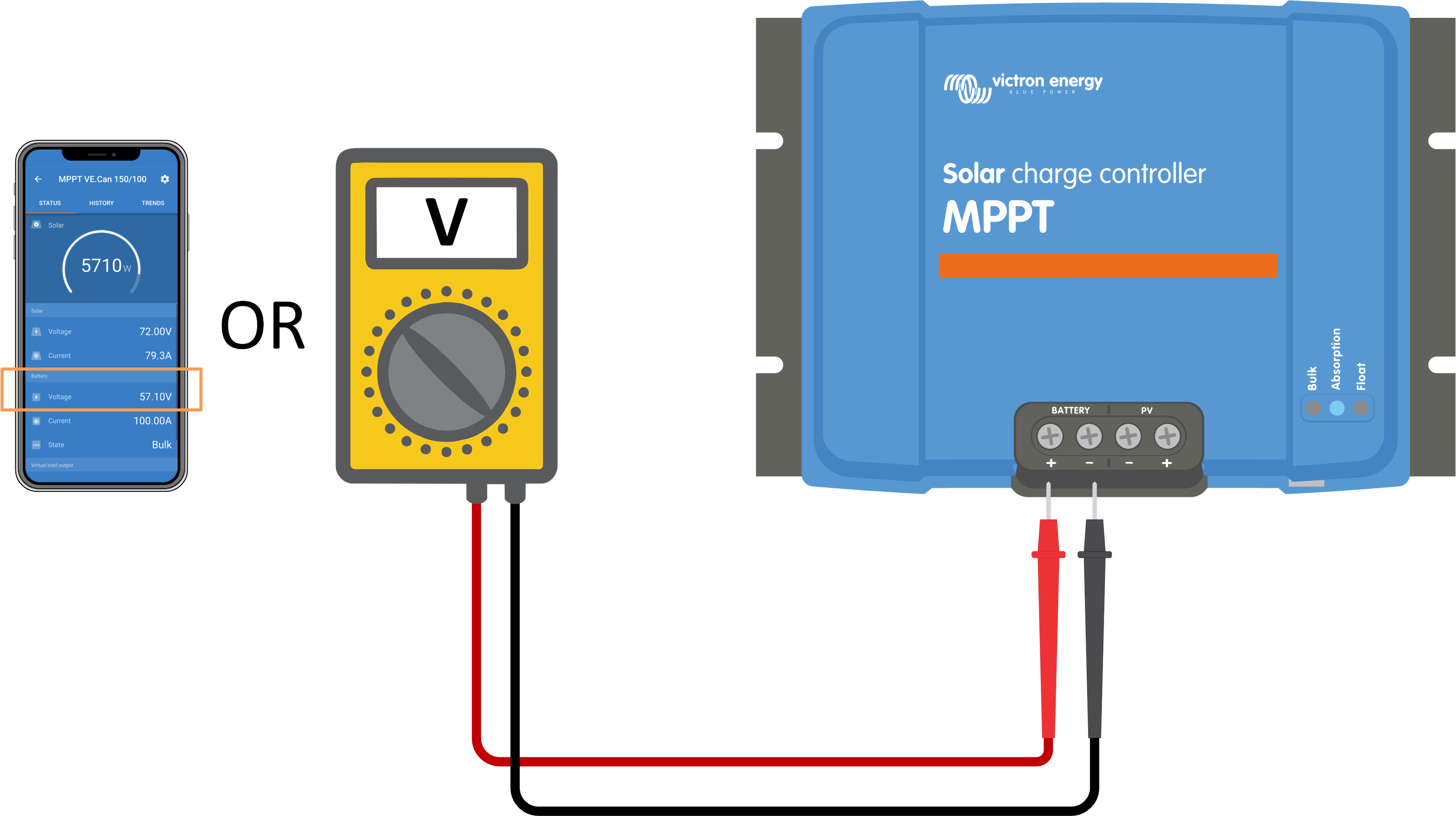
Step 2 | If the above step is impossible, use a multimeter in DC mode to measure the battery and PV voltages at the solar charger terminals.
WarningWARNING: Certain solar charger models may have PV voltages up to 250Vdc. Voltages exceeding 50V are generally considered dangerous. Only a qualified technician should handle dangerous voltages. | |
Step 3 | Compare both voltages. Remember that the PV voltage needs to be 5V higher than the battery voltage for charging to commence. | |

Insufficient solar irradiance is reaching the solar panels:
It is night.
There is cloudy or bad weather.
There is shade from nearby objects. See this shading blog story for more information.
The panels are dirty.
There are seasonal differences. The sun angle is lower in winter.
The panels have an incorrect panel orientation or inclination.
There are issues with a solar panel or the solar panel wiring:
There is a mechanical or electrical issue with an individual panel (or multiple panels).
Wiring problems, like loose wires, loose connections or incorrect crimped MC4 connectors.
Blown fuses.
Open or faulty circuit breakers.
Issues with splitters, combiners or incorrect usage of these components.
Incorrect PV array design or configuration:
The PV array is misconfigured. For example, there are an insufficient number of panels in a series string.
Reverse PV polarity:
The positive and negative PV wires have been mistakenly swapped when connected to the solar charger. For more information, see the Reverse battery polarity chapter.
8.3.2. Settings being edited on an external display
Charging is disabled when a MPPT Control external display is used to make configuration changes.
Once the settings menu is closed on the display, charging will resume.
8.3.3. Disabled in the settings
The charger has been disabled in the settings.
Check the VictronConnect app battery settings page to ensure that the charger has been enabled.
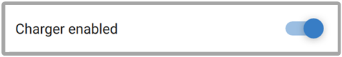 |
VictronConnect app charger enable/disable setting
8.3.4. Disabled by remote or BMS
The charger has been switched off via its VE.Direct port.
Note that in systems with lithium batteries together with an external BMS, it is typical for the solar charger to be switched on or off as needed. This happens when the BMS turns off the charger due to full batteries or low temperatures (below ~5°C). Charging automatically resumes when the batteries are discharged or have warmed up.
If the solar charger has unexpectedly been switched off, check the following:
VE.Direct RX port functionality check | |
|---|---|
The VE.Direct port can be used to switch the solar charger on or off by utilising its RX functionality in combination with, for example, a VE.Direct non-inverting remote on/off cable. | |
Step 1 | check if the RX port has been configured correctly. For more information, see the RX port settings chapter and the VE.direct protocol documentation. |
Step 2 | If a VE.Direct non-inverting remote on/off cable) is used, check if it is in good working order. |
Step 3 | If a non-Victron cable is used, check if it is configured correctly. For more information see the VE.direct protocol documentation. |
8.3.5. Low lithium battery temperature
Charging may be suspended if the battery temperature is low, as a part of the battery protection mechanism, without necessarily indicating a problem. The rationale behind this precaution is that lithium batteries are prone to damage when charged in temperatures below °5C.
If this protection is triggered unnecessarily, please reach out to your installer to adjust the related settings.
8.4. Solar charger is externally controlled
Managed batteries or an inverter/charger with an external control system (e.g., ESS system) can govern the solar charger via a GX device. The external system determines charging permissions and sets the charge voltage and currents.
When external control is active, it is visible on both the VictronConnect app and the GX device. This is normal behaviour and is not a fault.
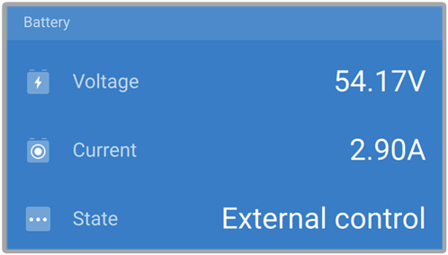 |
The VictronConnect app indicates that the charger is externally controlled.
8.5. Batteries are not charged
This chapter explains scenarios where the charger is active, but the batteries are not charging. In such cases, the VictronConnect app will show the charger as active with the correct charge voltage, but the charge current will be at zero or very close to zero.
The battery is fully charged, and no further current is required. This is normal behaviour and is not a fault. Refer to the Battery is full chapter for more details.
Reverse PV polarity. Refer to the Reverse PV polarity subchapter for more details.
PV voltage is too high. Refer to the PV voltage too high subchapter for more details.
Reverse battery polarity. Refer to the Reverse battery polarity subchapter for more details.
The solar charger is disconnected from the battery, possibly due to cable, fuse, or circuit breaker issues. Refer to the Battery not connected subchapter for more details.
Incorrect charger configuration, e.g., low charge voltage or current setting. Refer to the Battery settings too low subchapter for more details.
The charger is externally controlled (ESS or DVCC), which is normal and not a fault. Refer to the Solar charger externally controlled chapter for more details.
The temperature-compensated charging feature is active, and the battery temperature is too high, or the feature is misconfigured. Refer to the Wrong temperature compensation setting chapter for more details.
 |
The VictronConnect app shows a close to zero charge current.
8.5.1. Battery is full
Once the battery is full, the solar charger will stop or significantly reduce its charge current. This is especially evident when DC loads are not drawing power from the battery. It is important to note that this behaviour is normal and not a fault.
To determine the battery's state of charge (SoC), check the battery monitor (if available) or inspect the charge stage indicated by the solar charger. During the daily charge cycle, the solar cycle progresses through the following stages:
Bulk stage: 0-80% SoC.
Absorption stage 80-100% SoC.
Float stage: 100% SoC.
Be aware that the solar charger may detect the battery as fully charged when it's not. This happens if the charge voltages are set too low, causing the charger to switch from absorption to float stage prematurely. Refer to the Battery settings too low chapter.
8.5.2. Battery not connected
To ensure proper battery charging, a correct connection to the battery is crucial.
Be aware that that if the solar charger operates without a battery, it may seem connected, showing battery voltage and charge stage in the VictronConnect app, but the charge current will be negligible or zero.
Loose or missing battery cables.
Loose cable connections.
Poorly crimped cable terminals.
A blown (or missing) fuse in the battery supply cable.
Open (or faulty) circuit breaker in the battery supply cable.
Incorrectly wired battery cables.
Battery voltage check | ||
|---|---|---|
Step 1 | Use the VictronConnect app, a connected display or a GX device to read the solar charger battery voltage. Alternatively, use a multimeter to measure the battery voltage at the terminals of the solar charger.
| |
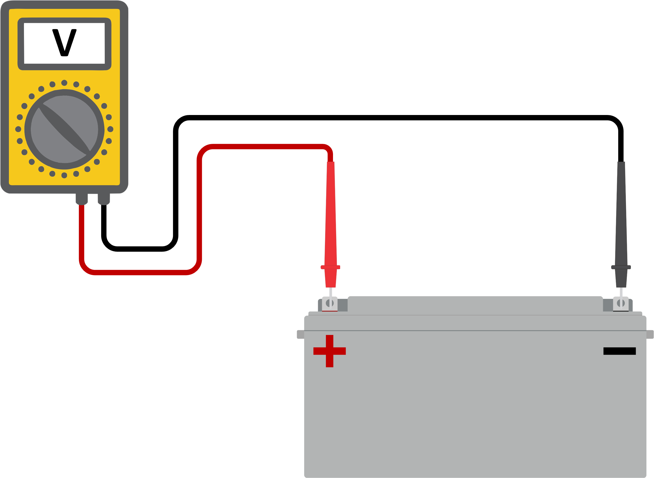
Step 2 | Use a multimeter to measure the voltage at the battery terminals.
| |
Step 3 | Compare the two voltages. | |
Step 4 | In case of a voltage difference, investigate the reason behind it by tracing the path from the solar charger to the battery to identify the cause.
NoteShould you come across a blown fuse, make sure to check the correct wiring of the battery polarity before replacing it. Refer to the Reverse battery polarity chapter. | |
8.5.3. Reverse battery polarity
Reverse polarity occurs when the positive and negative battery cables are accidentally swapped. This means the negative battery terminal connects to the positive solar charger terminal, and the positive battery terminal connects to the negative solar charger terminal.
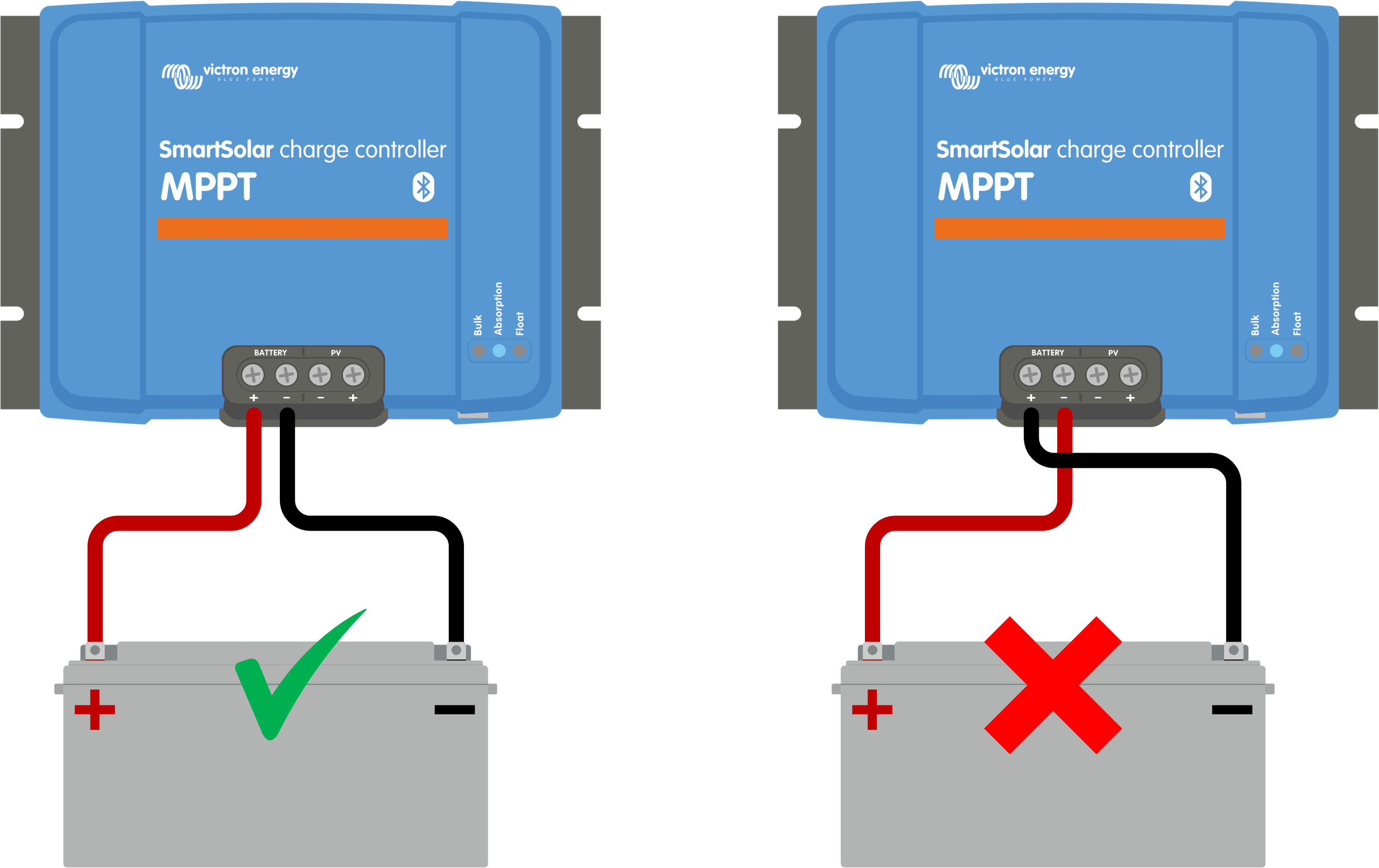 |
Examples of correct and incorrect (reverse) battery polarity.
Caution
Be aware that a red or positively labelled cable may not necessarily indicate the cable is positive. A wiring or labelling mistake during the solar charger installation is possible.
Always double-check the battery polarity before reconnecting the battery wires to the solar charger.
Reverse battery polarity can potentially damage the solar charger, causing its internal fuse to blow for fail-safe protection. This fuse might blow before the external fuse in the battery cable. However, please note that the internal fuse is situated in a non-serviceable area, and it cannot be replaced or repaired. If this happens, the solar charger should be considered faulty.
The solar charger is not protected against reverse battery polarity, and any resulting damage is not covered under warranty.
8.5.4. Battery settings too low
If the solar charger's charge voltage and current are well below the manufacturer's recommended levels, the battery charging process may become inadequate or excessively slow. Incorrect configuration can be a contributing factor, including:
Setting the "Battery voltage" parameter too low.
Setting the ''Absorption voltage" and "Float voltage" parameters too low.
Setting the "Max charge current" parameter to zero or an excessively low value.
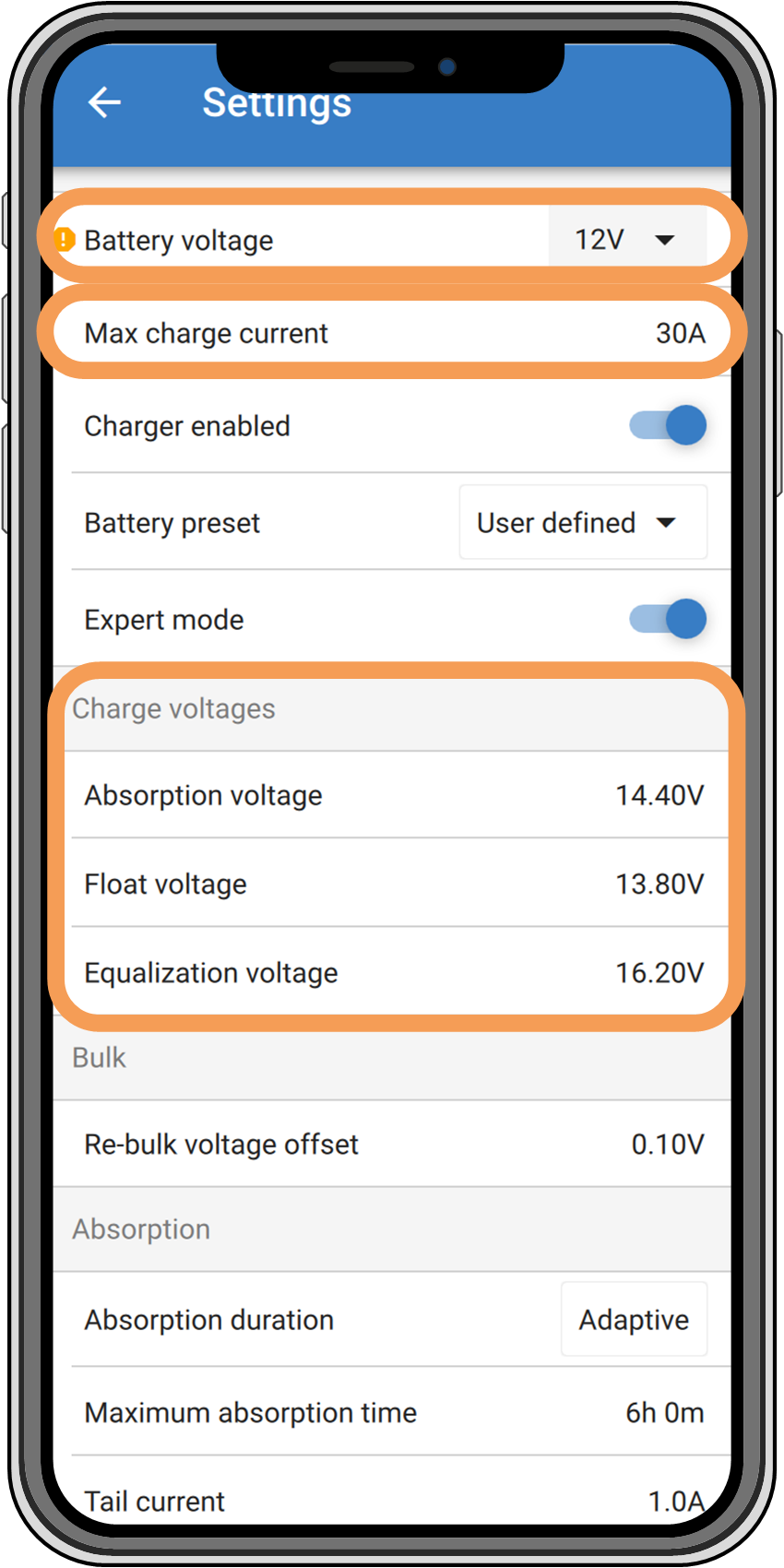 |
VictronConnect app, showing battery (system) voltage, charge current and charge voltages settings.
8.5.5. PV voltage too high
The PV voltage should always stay within the maximum rated limit of the solar charger, as indicated in its product name, type plate and Technical specifications. The solar charger can sustain damage based on the extent of the PV voltage height, and it's important to note that such damage is not covered by warranty.
Should the PV voltage exceed the maximum rated PV voltage, the solar charger will cease charging, showing an overvoltage error #33 with rapid blinking of the absorption and float LEDs. Charging resumes only when the PV voltage drops 5V below the rated maximum voltage.
During investigations into high voltage issues, it's essential to review the VictronConnect app, solar charger display, or GX device history. Check for the highest PV voltage recorded each day (Vmax) and past overvoltage warnings.
To avoid issues, check the open circuit voltage (Voc) rating of the PV array and ensure it is lower than the solar charger's maximum rated voltage. Use the MPPT sizing calculator on the solar charger product page. For PV arrays in cold climates or with night temperatures nearing or below 10°C, it's essential to consider possible increased output (more than its rated Voc). As a rule of thumb, maintain an additional 10% safety margin.
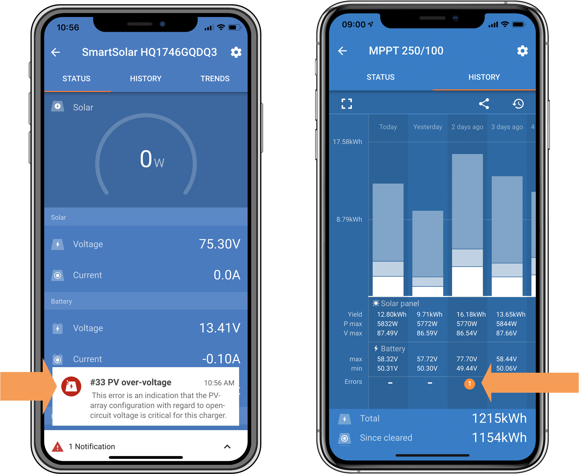 |
VictronConnect app error #33 indication on the status screen and history screen.
8.5.6. Reverse PV polarity
When the solar charger is installed within the published specifications, internal protection guards the PV input against reverse PV polarity, and no error is displayed in such cases.
Absence of battery charging with the charge current remaining at zero.
Excessive heat generated by the solar charger.
PV voltage reading zero or close to zero.
To verify, use a multimeter to ensure that the positive PV cable is correctly connected to the positive PV terminal and the negative cable is connected to the negative PV terminal.
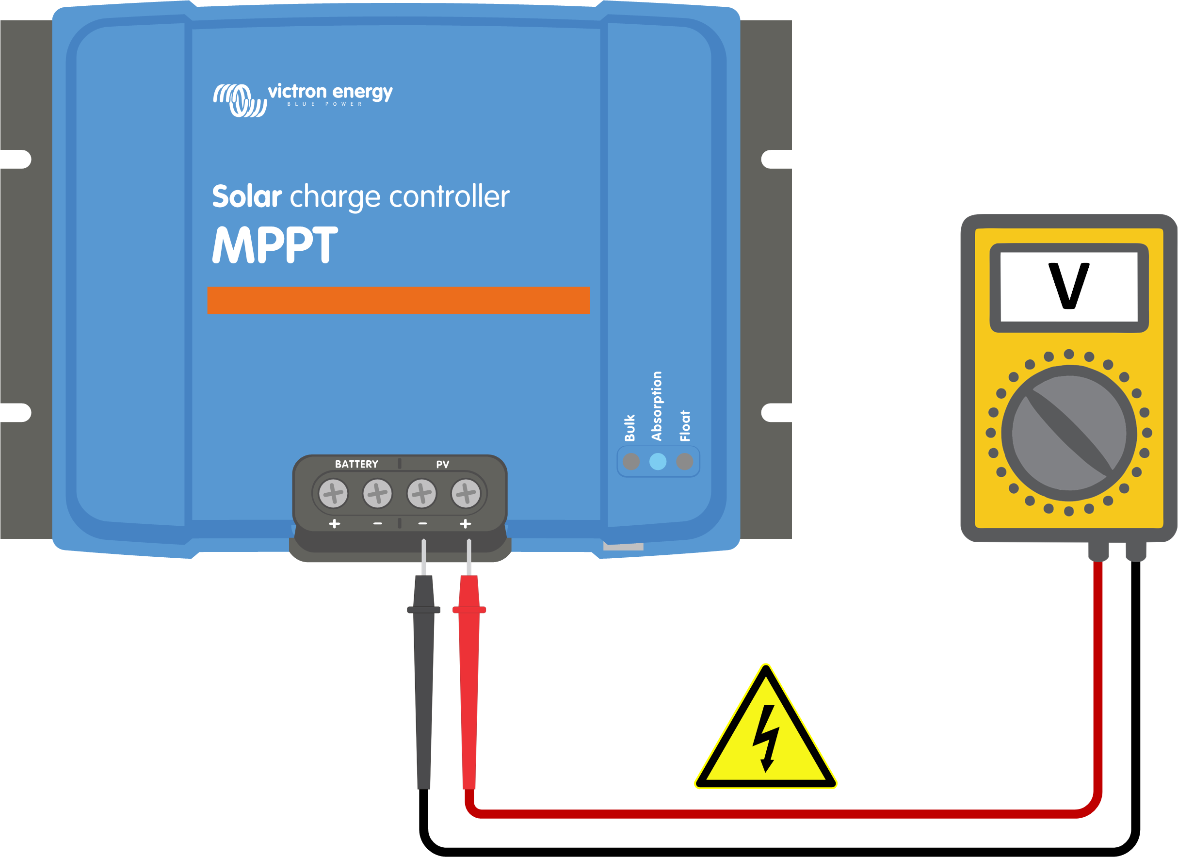 |
Warning
WARNING: Certain solar charger models may have PV voltages up to 250Vdc. Voltages exceeding 50V are generally considered dangerous. Only a qualified technician should handle dangerous voltages.
8.6. Batteries are undercharged
This chapter addresses the issue of undercharged batteries. It explores possible reasons why the solar charger might not be adequately charging the batteries and provides steps to check or resolve the situation.
Batteries taking too long to charge.
Batteries not being fully charged by the end of the day.
Charge current is less than expected.
Insufficient solar supply. Refer to the Insufficient solar supply subchapter.
High DC load. Refer to the DC load too high subchapter.
Voltage drop in battery cables. Refer to the Battery cable voltage drop subchapter.
Incorrect temperature compensation setting. Refer to the Temperature compensation setting incorrect subchapter.
Temperature difference between the solar charger and battery. Refer to the Temperature difference between solar charger and battery subchapter.
Battery charge voltages or current settings are too low. Refer to the Battery settings too low chapter.
8.6.1. Insufficient solar supply
Check if the solar charger reaches the float charge stage each day.
To investigate, check if the solar charger reaches the float charge stage each day. Utilise the VictronConnect app's history tab, where a histogram displays the daily charging durations in the Bulk, Absorption, and Float stages for the last 30 days. Clicking on a histogram column provides a breakdown of the charge stages.
You can use the charge times to assess whether the PV array is appropriately sized for your needs.
An inadequate number of solar panels.
Excessive DC load.
PV array issues causing reduced power output.
Solar charger is unable to reach full output. Refer to the Solar charger not achieving full output chapter.
Please note that this information does not apply to an ESS system. An ESS system will continuously be in the bulk charge stage while connected to the grid.
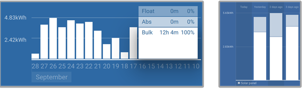 |
Left: Example of a system that is spending all its time in the bulk stage. Right: Breakdown of the charge stages - The system spends time in bulk and in the absorption stage.
8.6.2. DC load too high
The solar charger not only charges the batteries but also supplies power for the system's DC loads, such as lights, refrigerators, inverters, inverter/chargers and more.
Battery charging occurs only when the power generated by the PV panels exceeds the power consumed by the system's DC loads.
To check the PV array's power generation and load power usage:
If the system includes a properly installed and configured battery monitor, you can monitor the current flowing in (or out) of the battery, while the solar charger indicates the current generated by the solar array.
Use a current clamp and compare the current flowing from the solar charger into the battery and the current flowing from the battery into the DC system.
A positive sign alongside the current reading indicates current flowing into the battery, whereas a negative sign suggests current being drawn from the battery.
8.6.3. Battery cable voltage drop
If the battery cables experience a voltage drop, the solar charger will produce the correct voltage, but the batteries will receive a lower voltage, potentially leading to undercharged batteries. An excessive voltage drop of more than 2.5% is unacceptable.
Longer battery charging times.
Battery receiving a charge voltage that is too low.
Loss of charge power.
Increased heat in the battery cables.
Battery cables with insufficient cross-sectional area.
Poorly crimped cable lugs or terminals.
Loose terminal connections.
Faulty or loose fuse(s).
For more information on cabling issues and voltage drop, refer to the Wiring Unlimited Book.
Battery cable voltage drop check | ||
|---|---|---|
Step 1 | Make sure that the charger is charging with the full current, preferably in the morning. Use the VictronConnect app to confirm the output current. | |
Step 2 | Using the VictronConnect app or a multimeter, measure the voltage on the battery terminals of the solar charger.
| |
Step 3 | Measure the battery voltage on the terminals of the battery using a multimeter.
| |
Step 4 | Compare the two voltages to identify any voltage difference. | |

VE.Smart Networking can assist in mitigating a small cable voltage drop. However, for a substantial voltage drop, there may be an issue with the wiring between the solar charger and the battery, which requires rectification before proceeding.
In a VE.Smart Network a Smart Battery Sense or battery monitor measures the battery terminal voltage and transmits this via VE.Smart Networking to the solar charger. If the battery voltage is less than the solar charge voltage, the solar charger will increase its charge voltage to compensate for (small) voltage losses.
8.6.4. Temperature compensation setting incorrect
Improperly configuring the temperature compensation coefficient can lead to either undercharged or overcharged batteries.
Note that temperature compensation is typically applicable only to lead-acid batteries.
To determine the correct temperature compensation coefficient for your battery, consult the battery documentation. If uncertain, use the default value of -64.80mV/°C for lead-acid batteries, and for lithium batteries, disable the temperature compensation setting.
8.6.5. Temperature difference between solar charger and battery
For proper operation, it is crucial that the ambient temperatures of both the battery and the solar charger are equal, especially if the solar charger is not receiving battery temperature data.
Note
Note that this chapter does not apply if the solar charger is connected to a VE.Smart Network with a battery temperature measurement or is equipped with a temperature sensor.
At the beginning of the day, as soon as power is generated by the solar array, the solar charger will measure the ambient temperature and use it to temperature-compensate the charge voltage.
During the float stage, the solar charger will re-measure the ambient temperature and adjust the voltages accordingly.
Large differences in ambient temperature between the solar charger and the battery can lead to improper charging voltages for the battery.
For instance, if the solar charger is placed near a sunlit window while the batteries are located on a cold concrete floor in the shade, this temperature discrepancy can affect the charging process.
To ensure optimal performance, always ensure that the ambient conditions are equal for both the solar charger and the battery.
8.7. Batteries are overcharged
Warning
WARNING: Overcharging batteries can be extremely dangerous! There is a significant risk of battery explosion, fire, or acid leakage. To prevent accidents, do not smoke, create sparks, or have open flames in the same room where the batteries are located.
 |
Overcharging batteries can lead to severe battery damage and may be caused by the following factors:
Incorrect charge voltage settings. Refer to the Battery charge voltage settings too high subchapter.
Battery voltage setting too high. Refer to the Battery voltage setting too high subchapter.
Applying equalisation while the battery is not suitable for it. Refer to the Battery unable to deal with equalisation subchapter.
The battery is too small, old, has been mistreated in the past or is faulty. Refer to the Battery old, faulty or undersized subchapter.
8.7.1. Battery voltage setting too high
If the "battery voltage" setting in the VictronConnect app is configured to a voltage higher than the actual system voltage, it will result in overcharging the battery.
The solar charger automatically detects the battery voltage on the first install, and afterwards, the self-detection is disabled.
However, if the solar charger is moved from a 24V system to a 12V system, it may not recognise the system change. Consequently, it will continue charging with 24V battery charge voltages, while the connected battery is a 12V battery, leading to overcharging of the 12V battery.
To verify the "battery voltage" setting, use the VictronConnect app or a connected display. If the setting is incorrect, make sure to adjust it to the correct battery voltage.
8.7.2. Battery charge voltage settings too high
Batteries can be overcharged if the battery charge voltages are set too high.
Verify that all the battery charge voltages (absorption and float) are correctly configured to match the recommended voltages specified in the battery manufacturer's documentation.
8.7.3. Battery unable to deal with equalisation
When equalisation occurs, the battery charge voltage will be considerably high, and if the battery is unsuitable for equalisation, it may be overcharged.
It's essential to note that not all batteries can handle equalisation voltages. Check with the battery manufacturer to determine if the battery you are using requires a periodic equalising charge.
In general, sealed batteries and lithium batteries do not require equalisation and should not undergo the equalisation process.
8.7.4. Battery old, faulty or undersized
A battery that has reached the end of its service life or has been damaged due to improper use may be susceptible to overcharging.
A battery is comprised of multiple cells connected in series. In the case of an old or damaged battery, it's possible that one of these cells is no longer operational. During charging, the faulty cells will not accept charge, and the remaining cells will receive the broken cell's charge voltage, resulting in overcharging.
To address this issue, replace the battery. If the system includes multiple batteries, it's recommended to replace the entire battery bank rather than mixing batteries of different ages in one bank.
Determining the exact history of a battery during its lifetime can be challenging. The solar charger retains 30 days of battery voltage history. If the system has a battery monitor or is connected to the VRM portal, the battery voltages and cycle history can be accessed to assess the battery's overall health and whether it is nearing the end of its service life or has been misused.
Similar issues can arise if the battery is too small and charged with a significantly high current. The small battery will not be able to accept the total charge and will end up being overcharged.
Battery health check using battery monitor history data | ||
|---|---|---|
Step 1 | In the VictronConnect app, navigate to the battery monitor history screen. Or (if applicable) access the battery history via the VRM portal. | 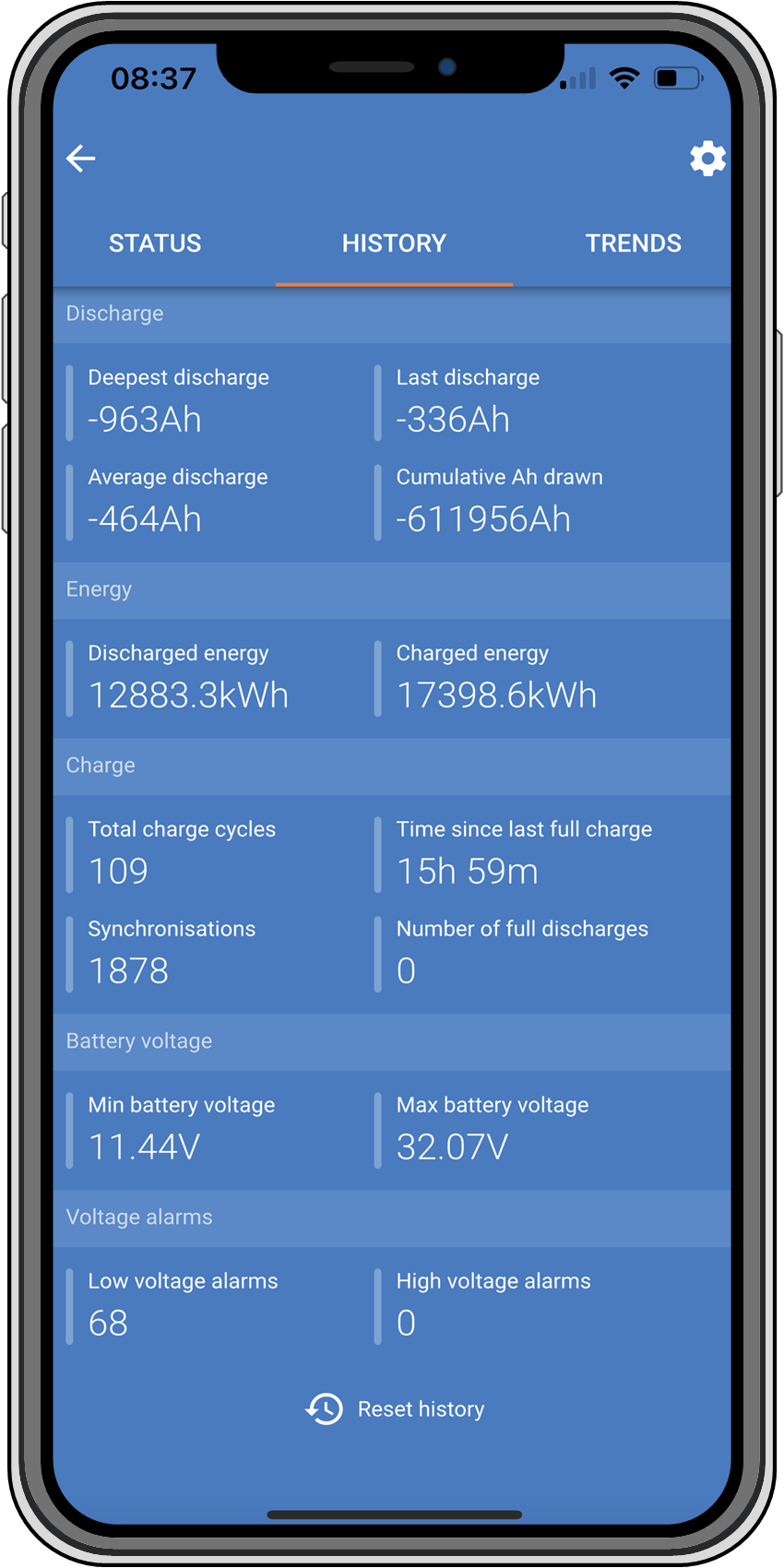 VictronConnect app showing battery monitor history |
Step 2 | Determine the number of charge cycles and synchronisations. Both indicate how many charge cycles the battery underwent. | |
Step 2 | Determine the average discharge or cumulative energy drawn. | |
Step 3 | Refer to the battery data sheet to find out how many cycles at what average discharge the battery is capable of. Compare this with the battery history and determine if the battery is approaching the end of its service life. | |
Step 4 | Check if the battery has been completely discharged at any point. Total and very deep discharges can damage a battery. Examine the deepest discharge, the lowest battery voltage and the number of full discharges. | |
Step 5 | Check if the battery has been charged with a too-high voltage. A very high charge voltage can damage the battery. Review the maximum battery voltage and the high voltage alarms. Verify that the measured maximum voltage has not exceeded the battery manufacturer's recommendations. | |
8.8. Solar charger not achieving full output
In addition to potential issues with the PV array, several other reasons can hinder the solar charger from reaching its full-rated output.
The PV array is too small. If the PV array's power rating is less than the solar charger's nominal power rating, the solar charger cannot output more power than the connected solar array can provide.
The PV array is not reaching its maximum power rating. Refer to the PV yield lower than expected subchapter.
The PV array is a mix of different PV panel types or models. Only use solar panels that are of the same brand, type and model.
Do not use optimisers. Nearly all optimisers contain an MPPT or other tracking mechanisms, which will interfere with the MPPT algorithm in the solar charger.
The PV array is wrongly configured. For a detailed explanation of how to configure PV arrays and properly use MC4 splitters and MC4 combiners, see the "Solar panel" chapter in the Wiring Unlimited Book.
The solar charger's maximum PV output power is related to the battery voltage. Refer to the Maximum output power relates to battery voltage subchapter.
The solar charger's PV electric connections are burned or melted, or MC4 connectors have been insufficiently crimped. Refer to the PV connections burned or melted subchapter.
The solar charger temperature is above 40°C. Refer to the Temperature above 40°C subchapter.
The batteries are either full or nearly full, causing no further power to flow into them.
There may be an issue with the battery. Refer to the Batteries are not charged and Batteries are undercharged chapters.
8.8.1. PV yield lower than expected
If the PV yield is not meeting expectations, start by checking the solar charger history in the VictronConnect app. Verify the total maximum power (Pmax) for each day and compare it with the array power.
To determine the potential solar yield per day for a specific PV array size in a particular geographical location, utilise the MPPT sizing calculator on the solar charger product page.
Low sun angle (morning or evening) or seasonal differences.
Cloud cover or adverse weather conditions.
Shading from trees or buildings.
Dirty solar panels.
Incorrect orientation or inclination of the solar panels.
Broken or faulty solar panels.
Issues with wiring, fuses, circuit breakers, or there is a cable voltage drop.
Incorrect usage or malfunctioning splitters or combiners.
Part of the PV array is not functioning correctly.
The PV array is too small for the desired output.
Mistakes in solar array configuration.
The batteries may be too small or aging, resulting in a reduced capacity.
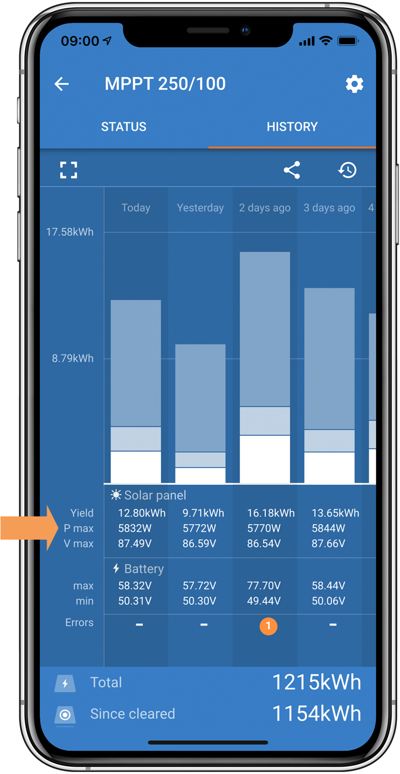 |
VictronConnect app history Pmax reading.
8.8.2. Maximum output power relates to battery voltage
The solar charger's output current is limited to its rated current, resulting in varying output power depending on the battery's voltage.
For instance:
In a 75/15 solar charger with a 15A output current rating, the power going into the battery will differ for a 12V battery and a 24V battery.
For a 12V battery, this is 15A x 12V = 180W.
For a 24V battery, this is 15A x 24V = 360W.
Thus, even though a 360W panel is connected to the solar charger, the output power into a 12V battery will be less than when connected to a 24V battery.
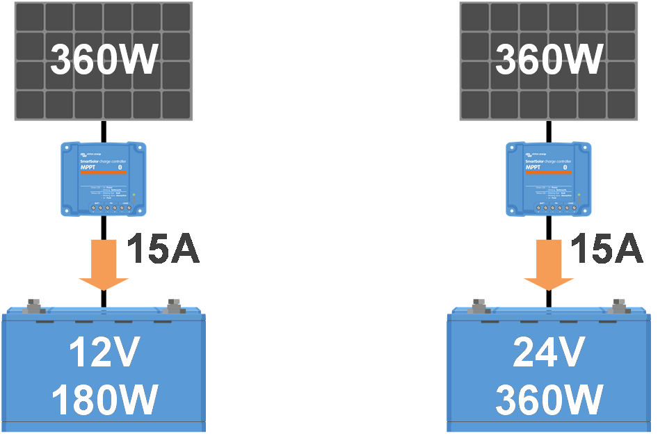 |
Example of differences in output power at different battery voltages
8.8.3. Temperature above 40°C
The solar charger operates up to 60°C, with full-rated output maintained up to 40°C. Above 40°C, the output will derate, reducing output power.
For efficient performance, consider the solar charger's mounting arrangement. Mount it vertically with terminals facing downwards to dissipate heat effectively. In closed enclosures, like cabinets, ensure proper airflow with mounted vents to allow cold air in and hot air out. In extremely high-temperature environments, mechanical air extraction or air conditioning may be necessary to maintain optimal performance.
8.8.4. PV connections burned or melted
Burned or melted PV cables or connections are not covered under warranty. This can occur due to the following reasons:
Loose screw connections.
Using cables with rigid core wire or rigid strands.
Soldering the core wire ends of the cables.
Using thin cables may result in higher currents when the PV voltage is lower. Refer to the Wiring Unlimited book for more information.
Inserting cable insulation too deeply into the connector.
Exceeding 30A per MC4 connector pair.
Incorrectly crimping MC4 connectors.
Using low-quality MC4 connectors.
8.9. Communication Issues
In this chapter, we address potential problems that may occur when connecting the solar charger to the VictronConnect app, other Victron devices, or third-party devices.
8.9.1. Bluetooth
Please note that Bluetooth interface issues are highly unlikely. If you encounter problems, they are probably caused by other factors. Use this chapter to quickly identify common causes of Bluetooth issues.
For a comprehensive troubleshooting guide, refer to the VictronConnect manual.
Bluetooth check | |
|---|---|
Step 1 | Check if the solar charger is powered up:
|
Step 2 | Check if the solar charger is equipped with Bluetooth:
|
Step 3 | Check that Bluetooth is in range:
|
Step 4 | The Windows version of the VictronConnect app does not support Bluetooth:
|
Step 5 | The solar charger is missing from the VictronConnect app device list:
|
Step 6 | Lost PIN code:
|
Step 7 | Communication without Bluetooth:
|
8.9.2. VE.Direct port
Problems with the VE.Direct port are uncommon, but if encountered, they are likely due to the following issues:
Try using a different VE.Direct cable to check if communication is established.
Ensure the connector is inserted properly and fully into the port.
Inspect the VE.Direct port for bent pins. If found, power the unit off by disconnecting it from the battery and the PV, and straighten the pins using long-nose pliers.
Connect the solar charger to a GX device to verify VE.Direct communication.
Check if the solar charger appears in the GX device list.
If it does not show up in the list, set the TX port function in VictronConnect to "Normal communication."
Verify the "TX port function" setting in VictronConnect matches the intended application.
Test the TX port's functionality using a TX digital output cable.
Confirm the "RX port function" setting in VictronConnect aligns with the intended application.
Test the RX port's functionality using a VE.Direct non-inverting remote on/off cable.
8.9.3. VE.Smart Networking
A VE.Smart Network is a wireless communication network that connects multiple Victron products using Bluetooth. If you encounter any problems with a VE.Smart Network, please refer to VE.Smart Networking manual.
8.10. Miscellaneous issues
This chapter describes issues that were not covered in the previous troubleshooting chapter.
8.10.1. Unable to operate as a DC-DC charger or power supply
Avoid using the solar charger as a DC-DC charger (e.g., to charge a 12V battery from a 24V battery bank). Connecting a battery to the PV terminals under certain operational conditions can damage the solar charger, which is not covered by the warranty. Instead, use a dedicated DC-DC charger or converter. Check our DC-DC converter product page for a complete product range.
Also, refrain from using the solar charger as a power supply without batteries connected. Although this operation won't harm the solar charger, it might not support all types of loads. Some loads may function, while others may not, particularly at low load power, where the solar charger's response might be too slow to maintain a constant voltage. Please note that support is not provided for such situations.
8.10.2. Interrupted firmware update
An interrupted firmware update is recoverable and there is no need to worry. Simply attempt to update the firmware once more.
8.10.3. Ground current
If a ground current is detected in the system during normal operation, take the following steps:
First, thoroughly inspect all the equipment connected to the system and check for any ground faults.
Next, verify the number of connections to ground in the system. Ideally, there should be only one point in the system connected to the ground, which should be at the battery.
For more information on system grounding, see the "System grounding" chapter in the Wiring Unlimited book.
Note that the solar charger is non-isolated and the minus of the PV input is at the same potential as the minus of the battery output.
8.10.4. PV Short relay reset procedure
Note
This procedure requires VictronConnect version v5.80 or later.
This procedure outlines the reset process for the internal protection mechanism, known as the PV Short Relay, in some of the newer MPPT charge controllers.
The protection consists of a latching relay, which is mounted across the PV Input. When the firmware detects a short between the PV inputs and the battery outputs, by monitoring the battery voltage for an over-voltage, it engages the relay and, as such, shorts the PV Input. See errors 80 to 83 in the Error 80 to 88 - PV Input shutdown chapter.
When to perform this procedure?
Applying a higher battery voltage than configured in the solar charger (eg. 48V battery to a 12, 24 or 36V configured charger), and then connecting the PV array, can cause the protection to “mis-trigger”. Meaning that the charger sees an over-voltage, and as such assumes that there is an internal fault and then engages the latching protection.
Recovering from such mis-triggers is the purpose of the here documented reset feature.
Follow the below procedure only if (a) the charger is not measuring any PV voltage when it should (i.e. during the day, with the sun shining, and all connections are ok). (b) the charger no longer charges the battery, and measuring the PV Input with a multimeter in resistance mode shows a few Ohms or lower. (c ) the charger no longer charges an error 80 to 87 is/was shown.
Latching relay reset procedure | |||
|---|---|---|---|
To recover from a latching relay failure follow this procedure to reset the relay. | |||
Step 1 | Disconnect both the battery and PV cables from the charge controller. |
| |
Step 2 | Reconnect the battery cables only. Do not connect the PV cables at this stage. | ||
Step 3 | Check the firmware version. For models with v1.xx firmware, ensure the firmware version is v1.73 or newer. For models with v3.xx firmware, ensure the firmware version is v3.18 or newer. | ||
Step 4 | Make sure no error 80 to 83 is active. If it is active, power cycle the unit. | ||
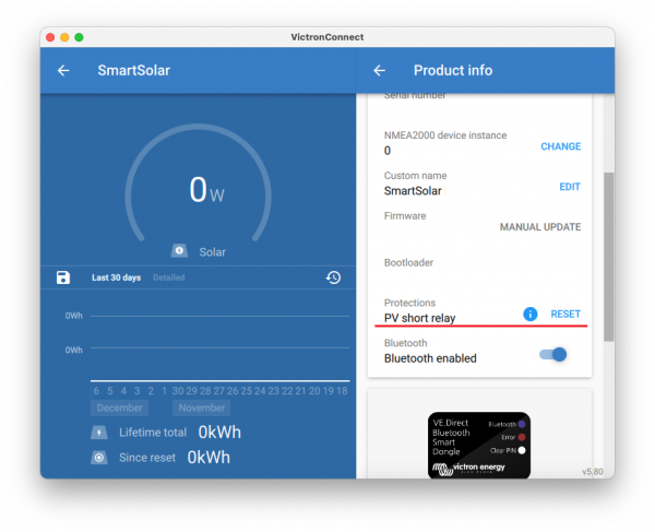
Step 5 | Navigate to the Product info page. Follow these steps:
The PV short relay reset feature is shown (see image on the right). NoteThis feature only shows if the connected charge controller supports it. See the list of models and serial numbers below. | ||
Step 6 | Then click the RESET button. It will gray out for a few seconds and return blue. A click might be heard. | ||
Step 7 | Reconnect the PV cables. | ||


Is my charger faulty if the reset menu is shown?
Not necessarily, as described above, the charger takes into account the PV and battery voltages to decide if the reset menu needs to be shown or not. In case, for example, the charger is connected to a 12V battery and no voltage is detected at the panel terminals (e.g. during the night), the menu will be shown, even if the charger is not faulty. Pressing the reset button in this case won't have any effect.
MPPT model name | Serial number |
|---|---|
BlueSolar MPPT 150/35 | HQ2601 and newer |
BlueSolar MPPT 150/45 | HQ2615 and newer |
8.11. Error code overview
The error codes in the following subchapters are potentially displayed in the VictronConnect app, on a remote display or a connected GX device. For the most up-to-date error overview, see this link: https://www.victronenergy.com/live/mppt-error-codes.
Furthermore, the solar charger utilises specific LED indications to signal particular errors. For an overview of these LED codes, please refer to the Victron Toolkit app.
8.11.1. Error 1 - Battery temperature too high
This error will auto-reset after the battery temperature has dropped. The solar charger will stop charging to prevent damaging the battery. The battery temperature can be received by an external sensor (like Smart Battery Sense or BMV) or measured by the charger when this feature is available.
8.11.2. Error 2 - Battery voltage too high
This error will auto-reset after the battery voltage has dropped. This error can be due to other charging equipment connected to the battery or a fault in the solar charger.
This error can also occur if the battery voltage (12, 24, 48V) is set to a lower voltage than the connected battery.
8.11.3. Error 17 - Solar charger overheated despite reduced output current
This error will auto-reset after the solar charger has cooled down. Check the ambient temperature and check for obstructions near the heat sink.
8.11.4. Error 18 - Solar charger over-current
This error will auto-reset. If the error does not auto-reset, disconnect the solar charger from all power sources, wait 3 minutes, and reconnect so it will power up again.
Switching on/off a very large load on the battery side.
Sudden change in irradiance is causing a temporary over-power in the solar charger.
Overload of the inverter ac output.
If possible, provide adequate cooling for the unit. A cooler unit can handle more current.
Reduce the load on the inverter.
Charge the battery before using the inverter. At higher battery voltages, the same amount of power requires less current.
8.11.5. Error 20 - Maximum bulk time exceeded
The maximum bulk time protection was a feature when the solar chargers were newly released in 2015 (or prior). This feature has now been removed.
If you see this error, update the solar charger to the latest firmware. If, after the update, you still see this error, then perform a "reset to factory defaults" and then reconfigure the solar charger.
8.11.6. Error 21 - Current sensor issue
If you see this error, update the solar charger to the latest firmware. If, after the update, you still see this error, then perform a "reset to factory defaults" and then reconfigure the solar charger.
Disconnect all wires and then reconnect all wires to force the solar charger to restart. Also, make sure the minus on the solar charger (PV negative and battery negative) is not bypassing the solar charger.
This error will not auto-reset.
If the error remains, please contact your dealer or distributor, as there might be a hardware defect.
8.11.7. Error 26 - Terminal overheated
Power terminals overheated, check the wiring, including the wiring type and type of strands, and/or fasten bolts if possible.
This error will auto-reset.
8.11.8. Error 28 - Power stage issue
This error will not auto-reset.
Disconnect all wires, and then reconnect all wires. If the error persists, the charger is probably faulty.
Note that this error was introduced in v1.36. So when doing an update, it might look like the firmware update caused this issue; but it doesn't. The solar charger was then already not performing 100% before the update; updating to v1.36 or later merely made the issue more visible. The unit needs to be replaced.
8.11.9. Error 33 - PV over voltage
This error will auto-reset after the PV voltage has dropped to a safe limit.
This error is an indication that the PV array configuration with regard to open-circuit voltage is critical for this charger. Check configuration, and if required, re-organise panels.
For more information, refer to the PV voltage too high chapter.
8.11.10. Error 38, 39 - PV Input shutdown
When these errors show, the PV Input is internally shorted to protect the battery from overcharging. Prior to any other troubleshooting, make sure to update to the latest firmware version.
The "Battery voltage" parameter (12/24/36/48V) is set incorrectly. Use the VictronConnect app to set the correct "Battery voltage" parameter.
Another device is connected to the battery, configured to a higher voltage. For example, an inverter/charger is configured to equalise at 17 Volts, while this is not configured in the solar charger.
Error 38: First, disconnect the solar panels and then disconnect the battery. Wait for 3 minutes, then first reconnect the battery and then the panels.
Error 39: The charger will automatically resume operation once the battery voltage drops below its maximum voltage setting (normally Equalisation or Absorption voltages). It can also take a minute to reset the fault.
If the error persists, the solar charger is probably faulty.
8.11.11. Error 40 - PV Input failed to shutdown
If the solar charger is unable to turn off the PV input, it will go into a safe mode in order to protect the battery from over-charging or having a high voltage on the battery terminals. In order to do that, the solar charger will stop charging and disconnect its own output. The solar charger will become faulty.
8.11.12. Error 80 to 88 - PV Input shutdown
When these errors show, the PV Input is internally shorted in order to protect the battery from over-charging.
Prior to any other troubleshooting, make sure to update to the latest firmware version.
The "Battery voltage" (12, 24, 36 or 48V) parameter is set incorrectly. Use the VictronConnect app to set it to the correct battery voltage.
Another device is connected to the battery with a higher charge voltage configuration. For instance, a MultiPlus is configured to equalise at 17V, while the solar charger has not been configured for equalise charging.
Ensure that the solar charger is running the latest firmware.
Errors 80 to 83: First, disconnect the solar panels, then disconnect the battery and then follow the procedure as described in the PV Short relay reset procedure chapter.
Errors 84 to 87: First, disconnect the solar panels and disconnect the battery. Wait for 3 minutes, then first reconnect the battery and then reconnect the panels.
If the error persists, the solar charger is probably faulty.
8.11.13. Error 116 - Calibration data lost
If the unit does not work and error 116 pops up as the active error, the unit is faulty. Contact your dealer for a replacement.
If the error is only present in the history data and the unit operates normally this error can be ignored safely. Explanation: when the units power up for the very first time in the factory, it does not have calibration data and an error 116 is logged. Obviously, this should have been cleared, but in the beginning, units left the factory with this message still in the history data.
SmartSolar models (not the BlueSolar models): upgrading to v1.4x firmware is a one-way trip, you cannot go back to an older firmware version once you upgrade to v1.4x. Reverting to older firmware gives error 116 (calibration data lost), this can be fixed by re-installing the v1.4x firmware.
8.11.14. Error 117 - Incompatible firmware
This error indicates that a firmware update did not complete, so the device is only partially updated. Possible causes are: the device was out of range when updating over the air, a cable got disconnected or power was lost during the update session.
To fix this the update needs to be retried, download the correct firmware for your device from the Victron Professional Portal
When your GX device is connected to VRM, you can do a remote firmware update using this firmware file. You can do this via the VRM website or using the VRM tab in VictronConnect. VictronConnect can also be used together with the firmware file to update using a Bluetooth connection.
The procedure to add the file to VictronConnect and start the update is described here: 9. Firmware updates
8.11.15. Error 119 - Settings data lost
The charger cannot read its configuration and has stopped. This error will not auto-reset.
Perform the below procedure to get it working again:
First, restore it to factory defaults. (top right in Victron Connect, click on the three dots).
Disconnect the solar charger from all power sources.
Wait 3 minutes, and power up again.
Reconfigure the charger.
Report this to your Victron dealer and ask for it to be escalated to Victron; as this error should never happen. Preferably include firmware version and any other specifics (VRM URL, VictronConnect screenshots or similar).