3. Installation
Warning
This product should be installed by a qualified electrician.
During installation ensure that the remote connector with wire bridge is removed (or switch off the remote on/off switch if installed) to be sure that the inverter cannot be switched on unexpectedly.
3.1. Physical installation
For a dimension drawing of the inverter, see the Appendix of this manual.
3.1.1. Location
To ensure a trouble free operation of the inverter, it must be used in locations that meet the following requirements:
Avoid any contact with water. Do not expose the inverter to rain or moisture.
Install the inverter in a dry and well-ventilated area.
For best operating results, the inverter should be mounted on a flat surface.
Mount as close as possible to the batteries. Try and keep the distance between the product and the battery to a minimum in order to minimize cable voltage losses.
There should be a clear space of at least 10cm around the appliance for cooling. Do not obstruct the airflow around the inverter. When the inverter is running too hot, it will shut down. When the inverter has reached a safe temperature level, the unit will automatically restart again.
Do not place the unit in direct sunlight. The ambient air temperature should be between -40°F and 149°F (-40°C and 65°C) (humidity <95% non-condensing). Note that in extreme situations the inverter’s case temperature can exceed 158°F (70°C).
Warning
Never mount the inverter directly above the batteries.
For safety purposes, this product should be installed in a heat resistant environment if it is used with equipment where a substantial amount of power is to be converted. Prevent the presence of e.g. chemicals, synthetic components, curtains or other textiles, etc., in the immediate vicinity.
3.1.2. Mounting
Mount the inverter against a sturdy wall or horizontally on a suitable ground surface.
Mount the inverter with four screws vertically up- or downwards or horizontally up- or downwards. See the table and figure below for the best mounting options.
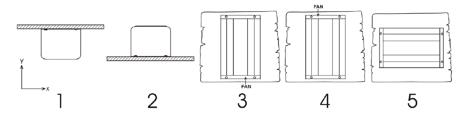
Mounting directions.
# | Mounting type | Recommended? | IP rating | Notes |
|---|---|---|---|---|
1 | Ceiling mounting (inverted). | No | n/a | |
2 | Base mounting | Yes | IP21 | |
3 | Vertical wall mounting, fan at the bottom. | Yes | IP20 | Be aware that potentially small objects or dust can fall into the inverter through the ventilation openings at the top. |
4 | Vertical mounting, fan on top. | No | n/a | |
5 | Horizontal wall mounting. | Yes | IP20 |
3.2. Electrical installation
For a connection overview drawing of the inverter, see appendix Connection overview.
3.2.1. AC output connection
Depending on the inverter model, the inverter is equipped with any of the following AC outlets:
Schuko (CEE 7/4).
IEC-320 (male plug included).
UK (BS 1363).
AU/NZ (AS/NZS 3112).
For a photo of the AC outlet type, see appendix AC outlet.
The inverter does not have a fuse in the AC output. The AC cabling is protected by a fast-acting current limiter in case of a short circuit and an overload detection mechanism which mimics the characteristics of a fuse (i.e. faster shutdown with larger overload). It is important to size your wiring properly, based on the inverter’s power rating.
Never connect the AC output of the inverter to another AC source, such as a household AC wall outlet or a generator.
Warning
The inverter has a floating ground. To ensure proper functioning of a GFCI (or RCCB, RCB or RCD) to be installed in the AC output circuit of the Inverter, an internal or external neutral to ground connection needs to be made. For more information see appendix Installation information neutral to ground connection.
3.2.2. Chassis to ground connection
Wire size for connecting the inverter chassis to ground:
The earth conductor from the earth lug on the chassis to ground should have at least half the cross-section of the conductors used for the battery connection.
The maximum conductor size that fits the earth lug is 25 mm². Use the table below to find the correct cross-section for the earth conductor.
The AC output is isolated from the DC input and the chassis . Local regulations may require a true neutral. For instructions, see appendix Installation information neutral to ground connection.
3.2.3. Remote connector
Remote on/off control of the inverter can be achieved with a simple on/off switch connected to the inverter remote connector.
The inverter will switch on when it has been switched to ON or ECO mode via the ON/OFF/ECO switch and when:
Contact is made between the remote connector H (left) terminal and L (right) terminal, for example via the wire bridge, a switch or the Inverter control panel.
Contact is made between the remote connector H (left) terminal and battery positive.
Contact is made between the remote connector L (right) terminal and battery negative.
Some usage examples of the remote connector are:
If the inverter is situated in a vehicle and is only allowed to operate when the engine is running. Connect the remote connector H (right) terminal to the vehicle ignition switch.
If the inverter is connected to a lithium battery the inverter can be controlled by the lithium battery BMS.
Warning
For safety purposes, the inverter can be turned off completely by removing the remote connector. Do this by pulling the remote connector out of its socket. This ensures that the inverter cannot be turned on anymore via its switch or Bluetooth. The user can now be certain that the inverter is definitely turned off and it cannot be accidentally turned back on by another user.
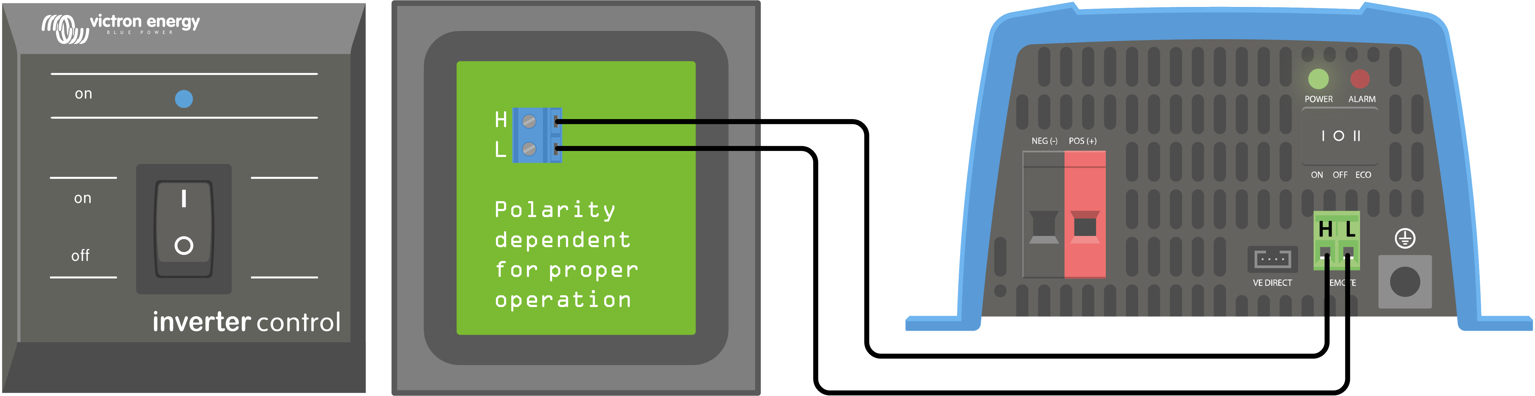
Inverter control panel
If a Inverter Control VE.Direct panel is used, it needs to be connected to the inverter remote connector as is indicated in below image. Note that the connection is polarity dependent for proper operation.
3.2.4. VE.Direct connection
The VE.Direct connection can be used for monitoring of the inverter via a GX device, or to connect to the VictronConnect app.
The following items can be connected:
A GX device or GlobalLink 520 using a VE.Direct cable.
A GX device using a VE.Direct to USB interface.
A computer running the VictronConnect app using the VE.Direct to USB interface.
A phone or tablet running the VictronConnect app using the VE.Direct Bluetooth Smart dongle.