7. Appendix
7.1. AC outlet
Depending on the model, the inverter is equipped with one of the following AC outlet types:
AC outlet | AC voltage | Image |
|---|---|---|
IEC-320 (male plug included) | 230V | 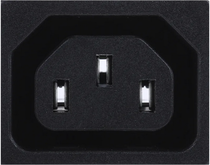 |
Schuko (CEE 7/4) | 230V | 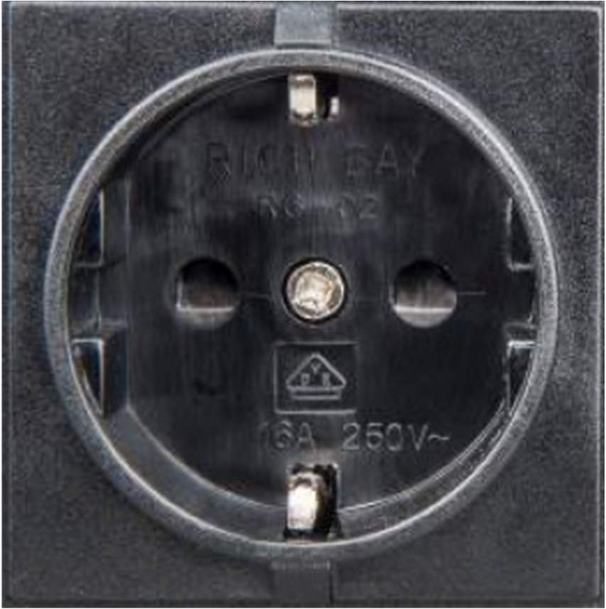 |
UK (BS 1363) | 230V | 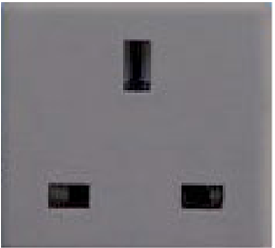 |
AU/NZ (AS/NZS 3112) | 230V | 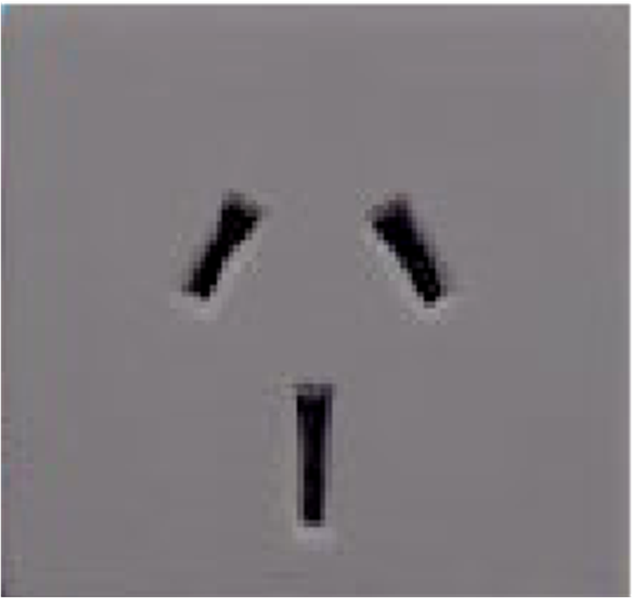 |
7.2. Connection overview
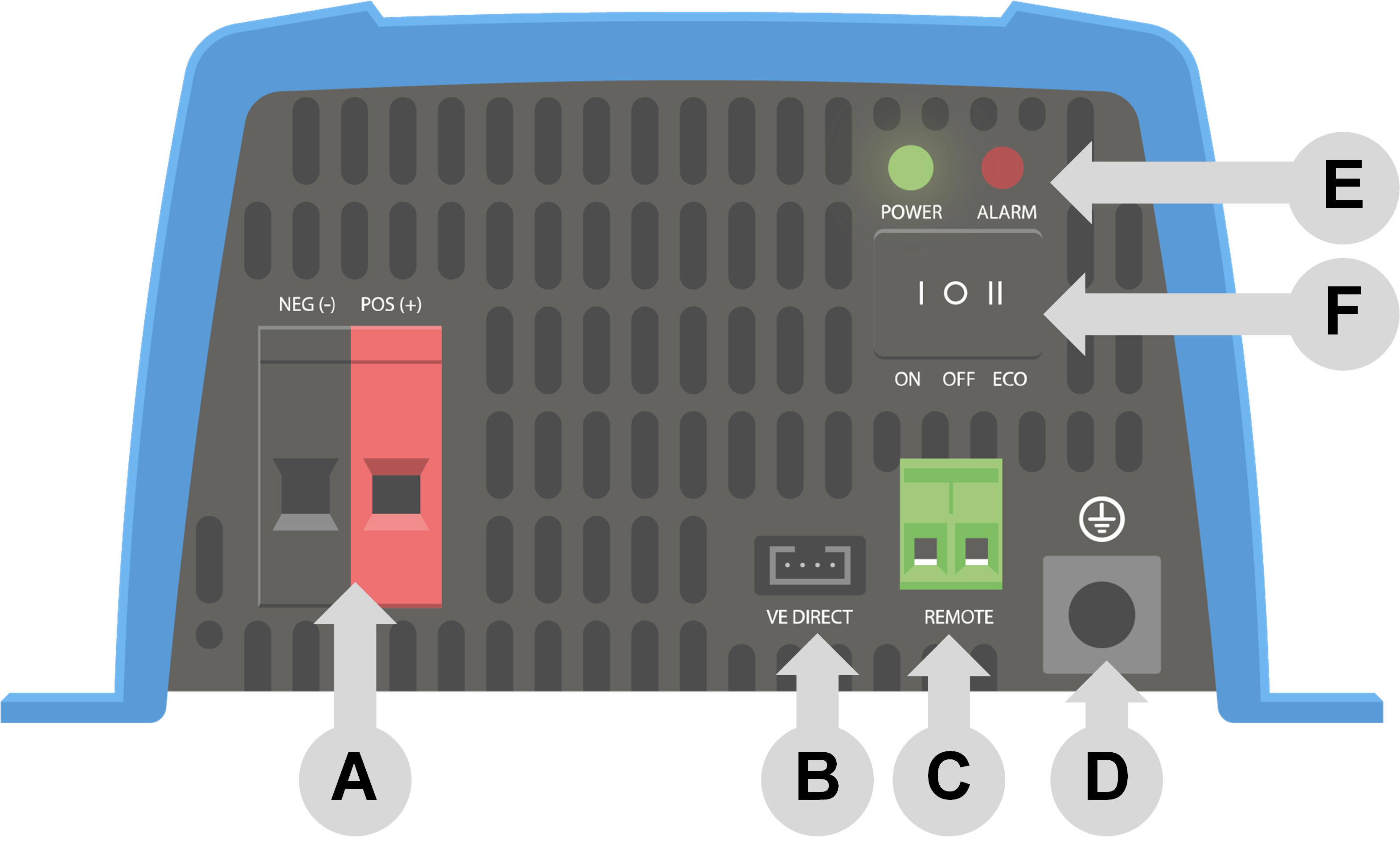
# | Description |
|---|---|
A | Battery connections |
B | VE.Direct connection |
C | Remote on/off terminal connection |
D | Chassis ground connection |
E | LEDs |
F | ON/OFF/ECO switch |
7.3. Installation information neutral to ground connection
Connecting the inverter neutral output to the chassis/ground
The AC output is isolated from the DC input and the chassis. Local regulations may require a true neutral. In this case one of the AC output wires must be connected to the chassis, and the chassis must be connected to a reliable ground. Inside the inverter a provision has been made to be able to connect the neutral and the chassis; the way to do this is explained below.
Please be sure to disconnect the battery when connecting the neutral to protective earth (PE).
An internal PE wire, which is used to connect the neutral and the chassis, is accessible after removing the plastic cover. A Torx T10 screwdriver is needed to loosen the four screws which hold the plastic cover.
For the 250 VA, 375 VA and 500 VA inverters:
Neutral floating
Position of the PE wire (indicated by the arrow):

Neutral connected to protective earth
Position of the PE wire (indicated by the arrow):

The earth wire from the chassis can be either connected to FJ1 (neutral floating) or to FJ2 (neutral connected to earth/chassis). The labels FJ1 and FJ2 are printed on the circuit board. The default position is FJ1, i.e. neutral is floating.
 |
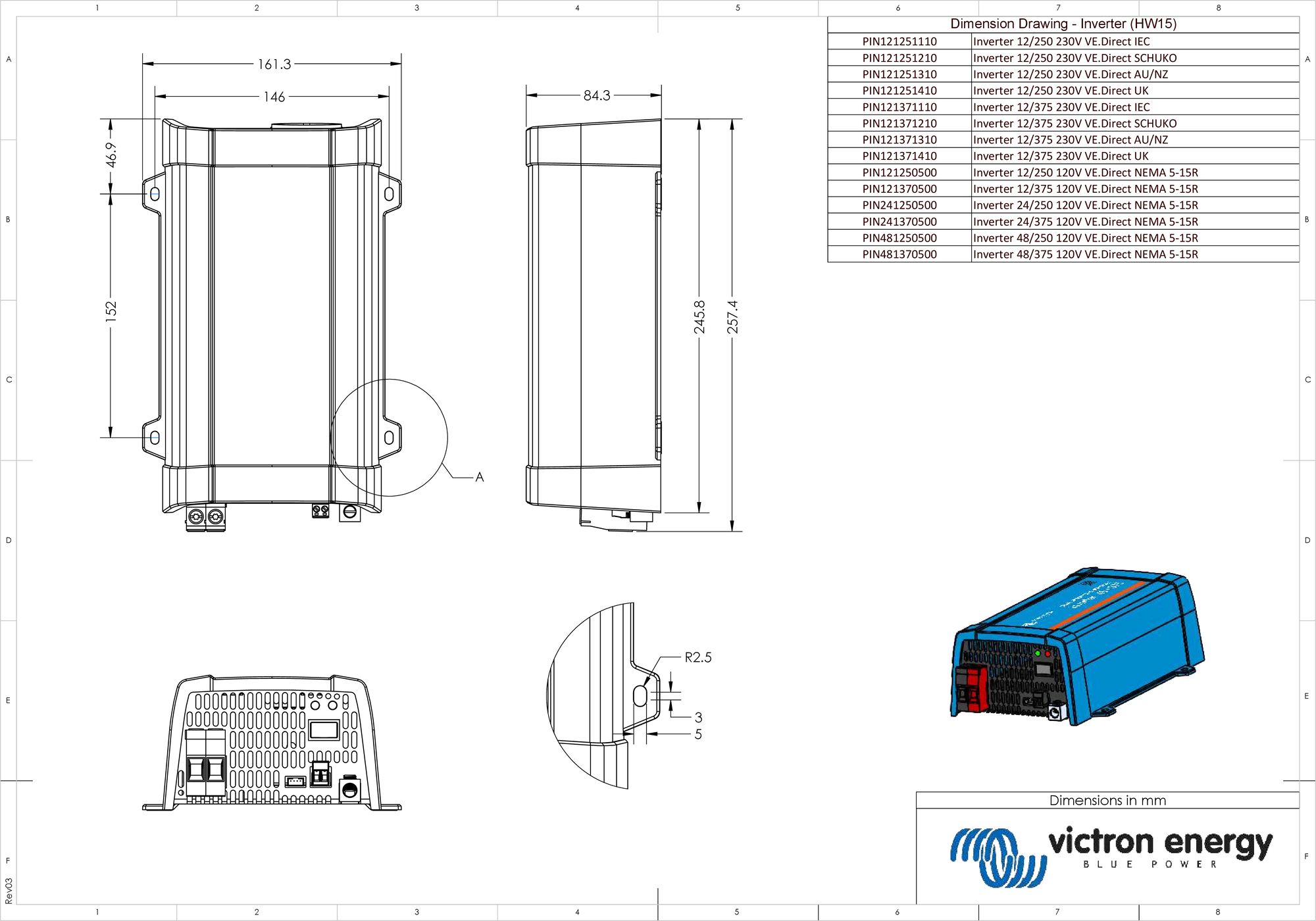
7.4. Dimensions 250 and 375 models
7.5. Dimensions 500 models

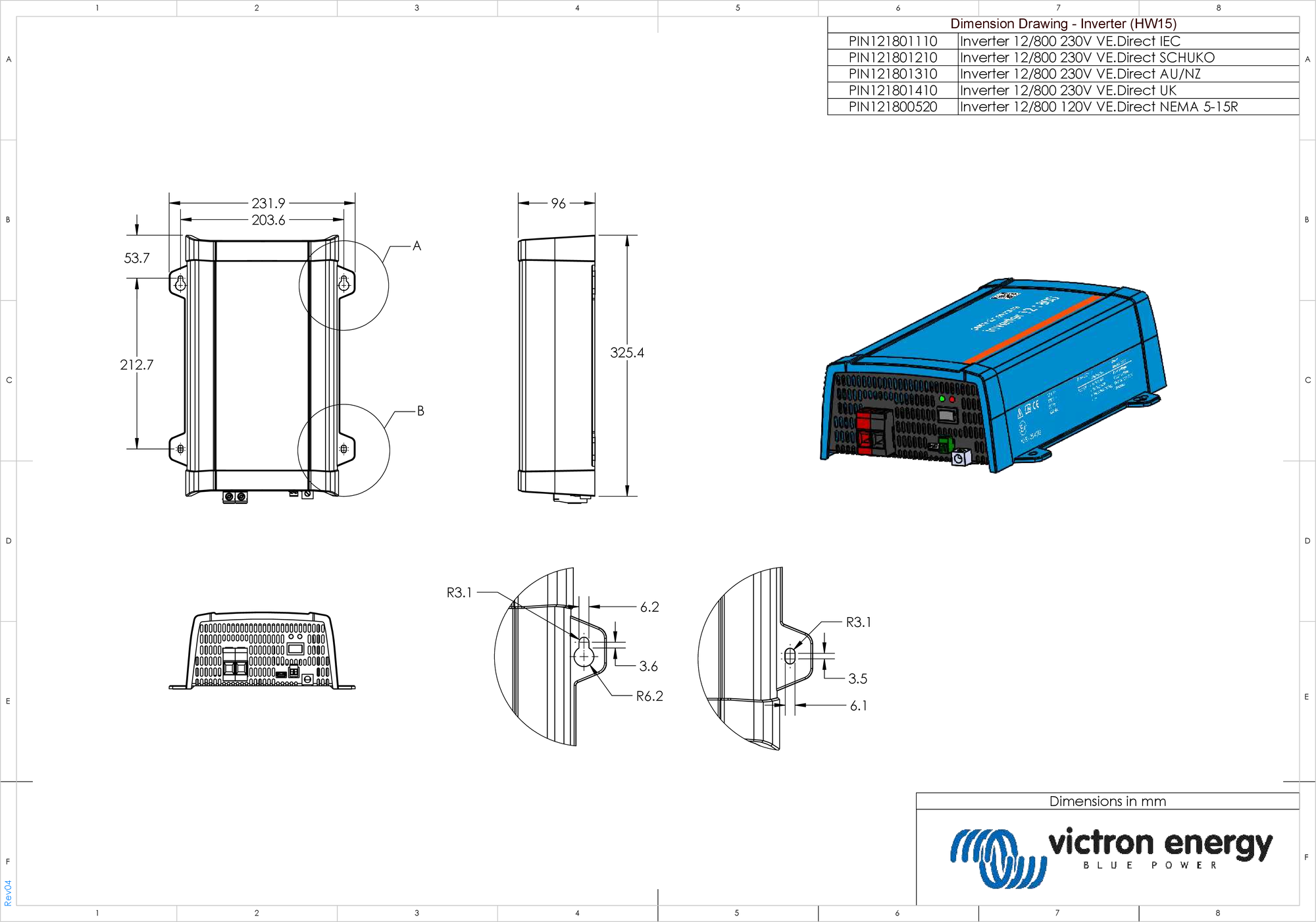
7.6. Dimensions 12/800 model
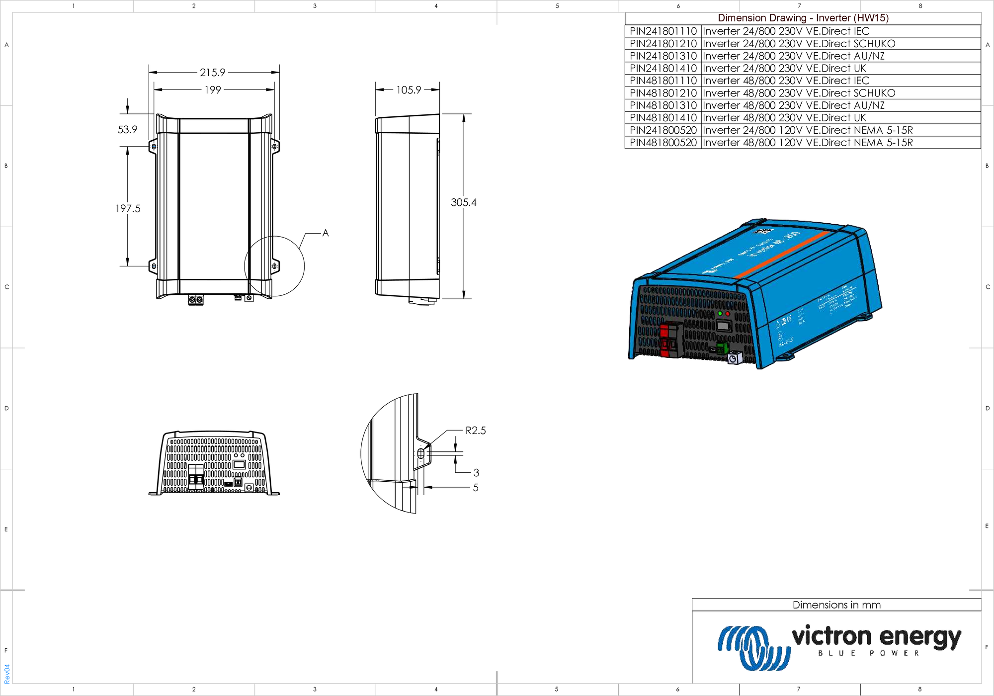
7.7. Dimensions 24/800 and 48/800 models
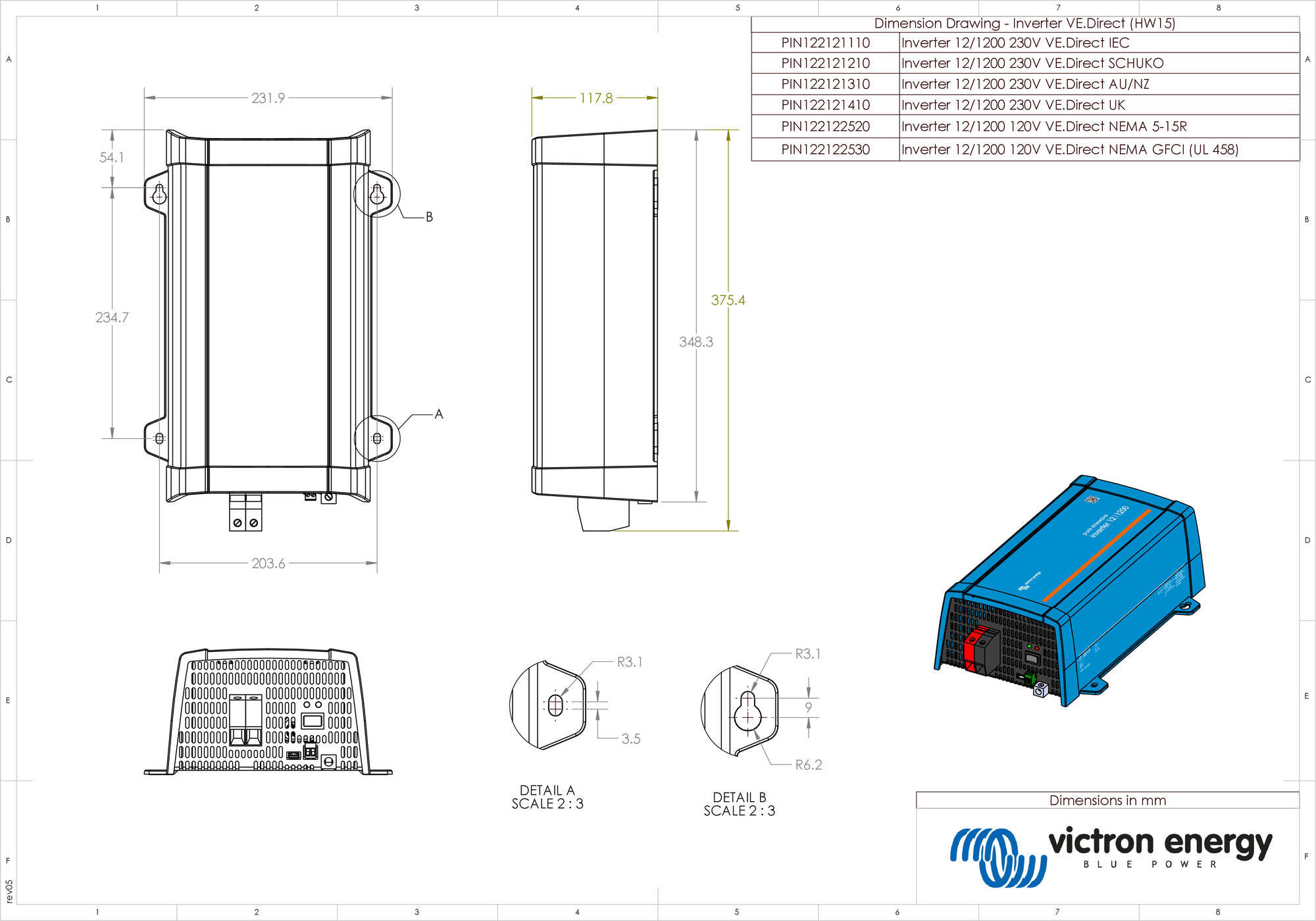
7.8. Dimensions 12/1200 model
7.9. Dimensions 24/1200 and 48/1200 models

7.10. Dimensions 12/1600 model
