3. Installation
3.1. Installing and wiring external current transformers (CTs)
The VM-3P5A requires external current transformers (CTs) for current measurement. CTs are not included and must be sourced separately. Victron Energy does not supply CTs for the VM-3P5A.
CT requirements
Use CTs with a 5 A secondary output
The CT primary current setting in the VM-3P5A must match the CT rating. For example, a CT marked 100/5 A must be configured as 100 A primary current. See Configuration & Monitoring for details on how to configure the primary current.
Wiring the CTs
Connect the CT secondary terminals as follows:
| 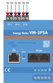 |
Ensure the polarity is correct on all phases. Reversed polarity will result in incorrect power and energy readings.
CT orientation
If the CT is marked with a direction arrow or polarity indicator, install it with the marking pointing from the AC source towards the loads. For CTs with S1/S2 polarity markings, S1 should face the AC source side and S2 the load side.
Important notes
Use one CT per phase and connect each CT to the corresponding input terminal (CT-1, CT-2, CT-3).
Ensure the phase voltage inputs and CTs correspond to the same phase.
Do not install CTs on bare conductors.
Follow the CT manufacturer’s installation instructions to avoid damaging the transformer.
CT extension cables may increase measurement noise. To minimise induced noise, use twisted pair wiring.
3.2. Power wiring and overcurrent protection
The VM-3P5A does not include a built-in fuse. External overcurrent protection must therefore be installed on each of the four voltage measurement inputs: N, L1, L2, and L3. A 500 mA fuse is required on each input.
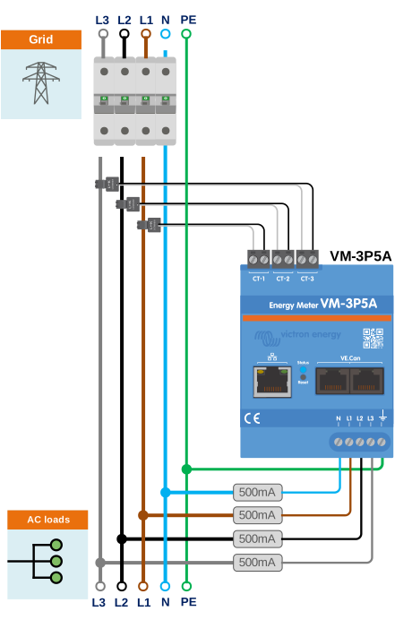
VM-3P5A circuit protection
3.3. Wiring examples by application
General AC wiring examples
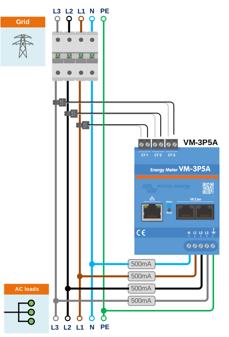 VM-3P5A 3-phase wiring when used as a grid meter | 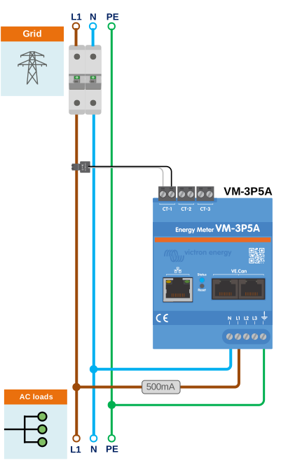 VM-3P5A 1-phase wiring when used as a grid meter | 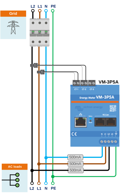 VM-3P5A split-phase wiring when used as a grid meter |
Specific AC wiring examples depending on application and role
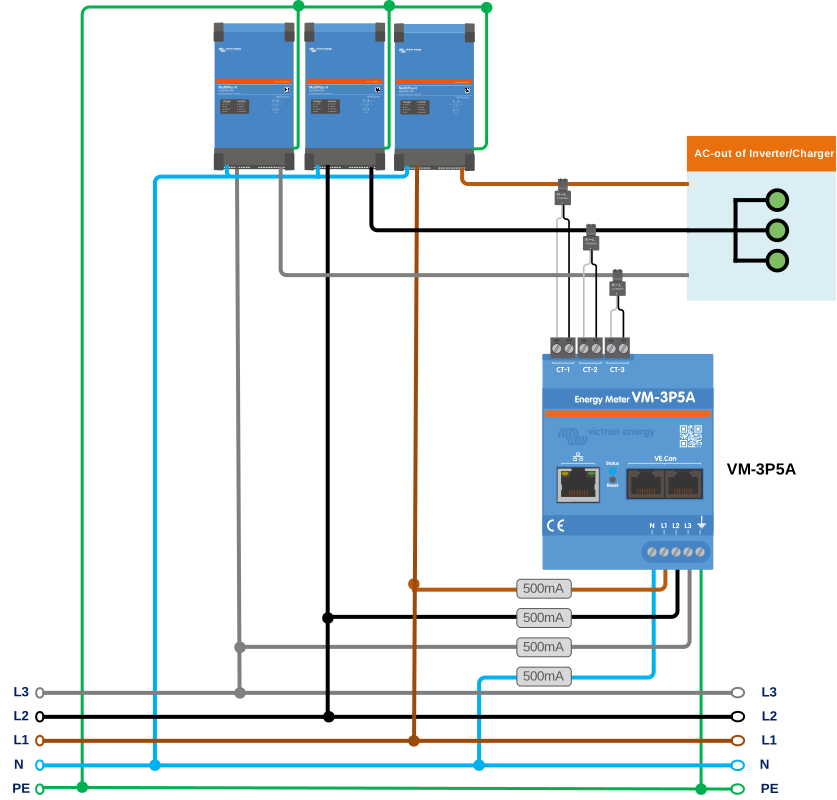
VM-3P5A 3-phase wiring - Role is set to measure AC loads
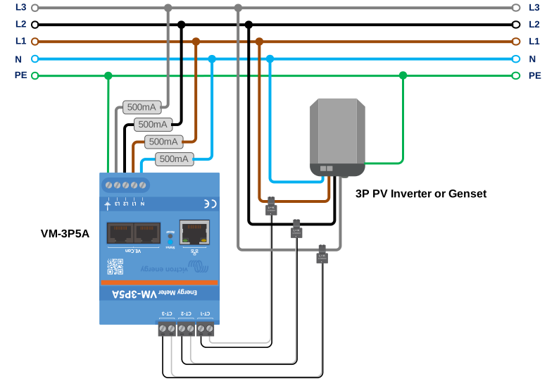
VM-3P5A 3-phase wiring - Role is set to measure a PV Inverter (or Generator)
3.4. Ethernet and VE.Can wiring
The VM-3P5A can be connected to the GX device either via VE.Can or Ethernet.
Suppose there is a local network with an Ethernet connection (via a router) to which the GX device is connected via Ethernet or WiFi. In that case, connecting the energy meter to the same network via Ethernet is reasonable.
Alternatively, you can connect the energy meter directly to the GX device via its VE.Can connectors. Ensure that the VE.Can network is properly terminated at both ends with the supplied VE.Can terminators.
For both applications, use a good quality Ethernet cable such as the Victron RJ45 UTP Cable, which can also be purchased from your Victron dealer in different lengths.
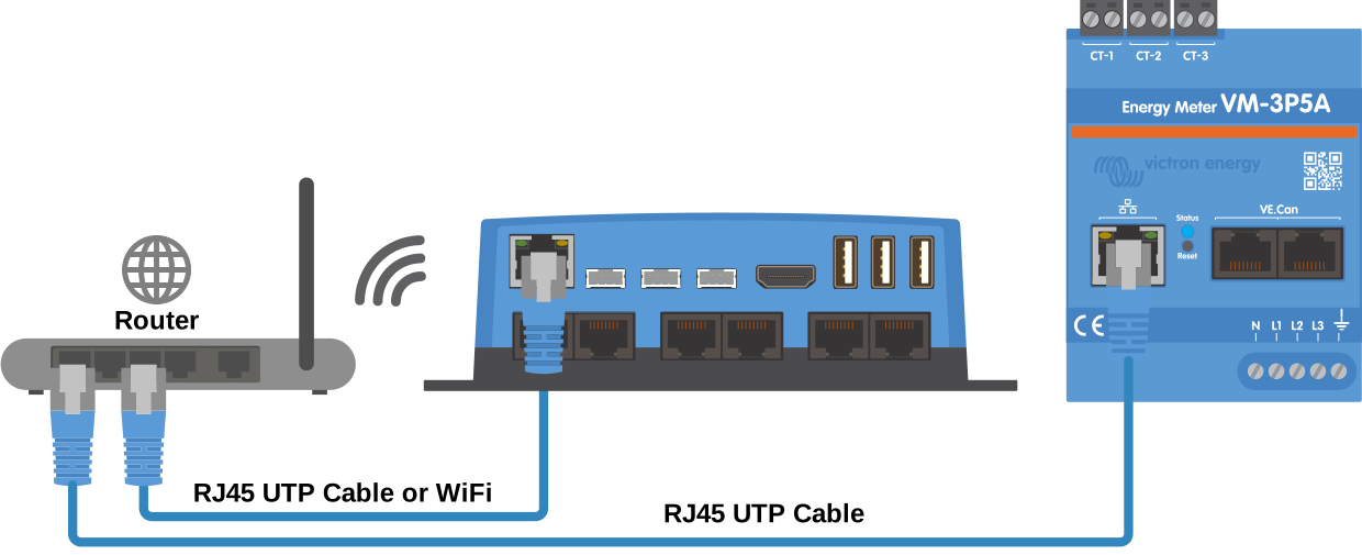
The VM-3P5A connected to the GX device via Ethernet
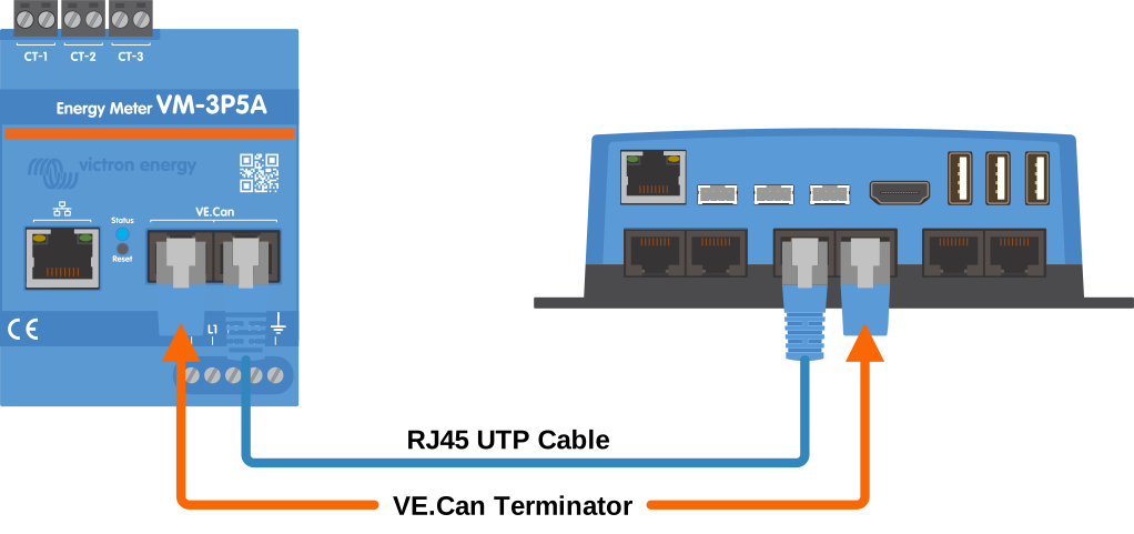
The VM-3P5A connected to the GX device via VE.Can