 Add this page to your book
  Remove this page from your book
  Manage book (
 Help
Help Table of Contents
GX Modbus-TCP Manual
1. Introduction
Modbus-TCP is a feature on all our GX devices eg Cerbo GX, and Venus GX.
Modbus-TCP is an industry standard protocol, that can be used to interface PLCs or other third party equipment with Victron products. Through the Modbus-TCP interface you can read and write data to the chargers, battery monitors, inverter/chargers and other products connected to the GX device.
Besides reading this GX Modbus-TCP Manual, make sure to also read the Modbus-TCP section in our Data communication whitepaper.
By default, Modbus-TCP is disabled. To enable it, go into the settings menu, scroll down to 'Services', and then enable the Modbus-TCP service.
2. Addressing, Unit-ID and Registers
2.1 Definitions
The Modbus-TCP protocol has two fields for addressing. There is the Unit-id, also referred to as Address, Station address or Slave-address in some PLC software. And the other field is the Register address.
- The Unit-ID is the device-selector: it tells the GX Device which connected device (ie. which charger, inverter, or battery-monitor) you want to read, or write from. The GX Device then acts as a Modbus-TCP gateway.
- The Register Address then determines the parameter to read or write: ie. voltage, or current, and so forth.
2.2 Unit-IDs
To see a list of available devices, and their Address, go to Settings → Services → Modbus/TCP → Available services:

Additionally this information is also documented on the ‘Unit ID mapping’ tab in the Modbus-TCP excel sheet.
For the overall system data, look for com.victronenergy.system in the excel sheet, and use Unit-ID 100.
Note that both Unit-ID 0 and Unit-ID 100 map to the same internal address. We recommend to use ID 100, since many Modbus-TCP clients and PLCs do not work with ID 0.
2.3 Register addresses
The list of available registers is in an Excel sheet, available for download on the Whitepapers section on our website.
Besides registers for connected Chargers, Inverters, and other products, there is also a set of registers that represent the entire system: com.victronenergy.system. This service is also where the System Overview pages in the GUI, and the VRM Dashboard get their data.
Note that not all list registers are available for each device. For example a BMV Battery Monitor has lots of readings: historical data such as maximum/minimum, for example. A canbus-connected lithium battery might not have all those parameters available. There is no information available on what type of product has what data available.
Use this table to map the definition in the 'dbus-service-name' in the Excel sheet to a product type:
| Device class | Product types | Registers |
|---|---|---|
| com.victronenergy.vebus | Inverters (VE.Bus), Multis, and Quattros | 3 to 60 |
| com.victronenergy.solarcharger | Solar chargers (both VE.Can and VE.Direct connected) | 771 to 790 |
| com.victronenergy.pvinverter | Grid-tie PV Inverters (Fronius, or Energy Meter) | 1026 to 1039 |
| com.victronenergy.battery | BMVs, CAN-Bus BMS connected batteries Extra parameter set for Lynx Ion and Lynx BMS product family | 259 to 319 1282 to 1301 |
| com.victronenergy.charger | Skylla-i and Skylla-IP44 | 2307 to 2322 |
| com.victronenergy.inverter | Inverters (with a VE.Direct connection) | 3100 to 3128 |
| com.victronenergy.tank | Tank levels | 3000 to 3005 |
| com.victronenergy.grid | Energy meters configured to measure the grid | 2600 to 2609 |
| com.victronenergy.gps | GPS | 2800 to 2807 |
| com.victronenergy.tank | Tank sensors | 3000 to 3007 |
| com.victronenergy.genset | Generators | 3200 to 3223 |
| com.victronenergy.temperature | Temperature sensors (1) | 3300 to 3305 |
| com.victronenery.meteo | IMT solar irradiation sensors | 3600 to 3603 |
(1): These are the auxiliary temperature sensors built-in to our GX devices, such as the Venus GX. For details, see the GX devices datasheet. Battery temperatures as measured by an Inverter/charger, Charger or Solar Charger are available together with the rest of that device's data, not under com.victronenergy.temperature.
3. Supported Modbus-TCP function codes
The supported function codes are:
- ReadHoldingRegisters = 3
- ReadInputRegisters = 4
- WriteSingleRegister = 6
- WriteMultipleRegisters = 16
Note that there is no difference between function code 3 and 4.
5. Mapping example
The purpose of this example is to show how to interpret the information in the worksheets of the excel sheet containing the Modbus-TCP mapping. This excel sheet is available for download from our website on the Color Control page.
To request the input voltage of a Multi or Quattro, connected to the VE.Bus sockets on the GX device, use the following settings: Unit-ID 246, and set the data address of the first request register to 3.
The Modbus-TCP reply will contain 2302. Divide it by 10, as specified in cell E3, and then you have the voltage: 230.2 Volts AC.
6. Error codes and trouble shooting
6.1 The common cause: Unit-ID / Register combination
In case a certain read or write is not successful, most likely there is an issue in the unitid/registerid combination.
Besides double checking the mapping, there are two ways to see where the error lies. One is to check the last error as shown in the GX Device menus. And secondly you can look at the error code as is visible on (most but not all) PLCs. See the two sections below for details.
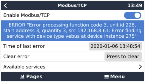
6.2 Looking up the last Modbus-TCP Error on the GX Device
To see why a certain register is not available, use the Settings → Services → Modbus-TCP menu. It shows the last error, and reason for that error.
6.3 Error codes
These error codes are returned by our software to the PLC; and most PLC software tools allow seeing them.
| Code | Name | Description |
|---|---|---|
| 0x01 | IllegalFunction | The requested function is not supported. |
| 0x02 | IllegalDataAddress | The requested Unit-ID is available, but one or more of the requested register(s) does not exist. |
| 0x03 | IllegalDataValue | The requested quantity of registers is invalid. See the modbus specs, http://www.modbus.org/specs.php, for the limits per function code. |
| 0x0A | GatewayPathUnavailable | The requested Unit-ID is defined in the mapping list, but there is no device found on the mapped port. Double check the Unit-ID mapping list in the excel sheet, and make sure that the device is properly connected to the GX device, switched on, and that its data is available on the GX device display. |
| 0x0B | GatewayTargetDeviceFailedToRespond | Requested Unit-ID not found in the mapping list. Double check the Unit-ID mapping list in the excel sheet. |
7. Support
The recommended method for support on Modbus-TCP questions is to use the Modifications section on Victron Community. Its frequently visited by many people using Modbus-TCP and other methods of integrating with Victron products.
Direct company support is only offered on a limited basis. For such support, contact our Victron representative.
8. FAQ
Q1: Which products can be interfaced via Modbus-TCP?
All products that can be connected to the Color Control GX.
Q2: Can I change a configuration setting in a Multi - for example: the absorption voltage?
No.
Q3: Can I request multiple registers at the same time?
Yes, you can! Though make sure not to include non existing registers in your query. Querying register 1 to 100 for example will not work, since registers 1 and 2 do not exist.
Q4: Can I implement more features myself?
Yes, you can! We are, slowly, making the Color Control code open source, and the Modbus-TCP sources are already available on https://github.com/victronenergy.
Q5: In a parallel or three-phase system, how can I address a single unit?
You cannot interface with them individually if they are configured for parallel-working; or as a three-phase system. Neither is it necessary to address units individually as Modbus-TCP provides system-totals as well as 'per phase' information.
Q6: Will unit-id's change after a reboot or loss of power?
No.
Q7: Advanced debugging
If all unit-id's and register-addresses have been checked and re-checked, and still the connection doesn't work, you could try looking at the Modbus-TCP log file on the GX device.
Follow these steps:
- Login with SSH (use for example Putty in Windows - or simply type ssh root@[ip address here] on a Linux or Mac terminal console.
- List the latest log file:
cat /var/log/dbus-modbustcp/current | tai64nlocal
In case of any errors, the output will look like this:
2016-01-08 16:34:24.658248500  INFO 2016-01-08T16:34:24.657 [Server] New connecion:  "141.138.140.60:41792"
2016-01-08 16:34:24.695846500 ERROR 2016-01-08T16:34:24.689 "Error processing function code 3, unit id 247, start address 258, quantity 42 :" "Unit id is available, but start address does not exist"
2016-01-08 16:34:24.753921500  INFO 2016-01-08T16:34:24.753 [Server] Disconnected:  "141.138.140.60:41792"
In most cases the problem will be found in either the unit's id address; or the register addresses. Double check the numbers shown in the output with the numbers as used in your Modbus-TCP software or PLC.
Q8: Does Modbus-TCP support ESS?
Yes. See the ESS mode 2 and 3 manual for more details.