4. Configuration
The inverter is ready for use with the standard factory settings (see the Technical specifications chapter).
The inverter can be configured using the VictronConnect app. Connect using a smartphone or tablet via Bluetooth or using a computer via USB and a VE.Direct to USB interface).
Warning
Settings may only be changed by a qualified engineer.
Carefully read the instructions before changes are made.
4.1. AC output voltage and frequency
The inverter is set by default at 230Vac.
The AC output voltage and frequency can be set to a different value according to below table.
Model | AC output voltage range | Frequency range |
|---|---|---|
230Vac models | Between 210Vac and 245Vac | 50Hz or 60Hz |
4.2. ECO mode and ECO settings
The inverter is equipped with ECO mode. ECO mode is activated via the VictronConnect app.
When the inverter is in ECO mode, it will reduce its power consumption by approximately 85% when there are no loads connected to the inverter.
When the inverter is in ECO mode, the inverter will switch to search state when there is no load or a very low load. While in the search state, the inverter is off and will switch on every 3 seconds for a short period (adjustable). If the inverter detects a certain size load (adjustable) the inverter will go back to normal operation mode. Once the load drops below a certain level, the inverter will go back to ECO mode.
Below table indicates the default settings and setting range of the ECO parameters:
Parameter | Default value | Range |
|---|---|---|
Wake-up minimum power | 14VA | 14VA - inverter rating |
ECO mode search interval | 3s | 0 - 64s |
ECO mode search time | 0.16s | 0.08 - 5.00s |
Note
Note that the required ECO mode settings are heavily dependent on the type of load: inductive, capacitive, non-linear. Adjustment for specific loads may be needed.
4.3. Low battery alarm and charge detect settings
The inverter has two different types of low battery shutdown modes:
Low battery shutdown based on battery voltage. This is the "low battery shutdown" voltage.
Low battery shutdown based on battery voltage as a function of battery load. This mode is disabled by default. See next chapter Dynamic cut off for more information.
Once the inverter has shut down due to a low battery (regardless of the mode):
The inverter will restart again once the battery voltage has increased above the "low battery restart and alarm" level.
The inverter will clear the low battery alarm once it detects the battery is being charged. This is the "charge detect" voltage.
Battery voltage | Low battery shutdown | Low battery restart & alarm | Charge detect |
|---|---|---|---|
12V | Default: 9.3V Range: 0-100V | Default: 10.9V Range: 0-100V | Default: 14V Range: 0-100V |
24V | Default: 18.6V Range: 0-100V | Default: 21.8V Range: 0-100V | Default: 28.0V Range: 0-100V |
4.3.1. Dynamic cut off
The "Dynamic cut off" feature makes the low battery shutdown protection a function of the battery current drawn from the battery in relation to the battery voltage.
When a high current is being drawn from the battery, a lower cut off voltage threshold is being used, for example 10V. And similarly, when the battery is only being discharged slowly, a high cut off voltage is used, for example 11.5V.
In this way, a voltage drop, caused by the internal resistance in the battery, is compensated so that the battery voltage becomes a much more reliable parameter to decide when to stop discharging the battery.
The "Dynamic cut off" feature is most useful for batteries with a high internal resistance, like OPzV and OPzS batteries. It is a bit less relevant for GEL and AGM batteries and perhaps even irrelevant for lithium batteries. The below graph shows the discharge ratio versus battery voltage curve for the different battery types. You can see that the lithium curve (LiFePO4) is nearly flat compared to the OPzV and OPzS curve.
The curve can be adjusted in the VictronConnect app.
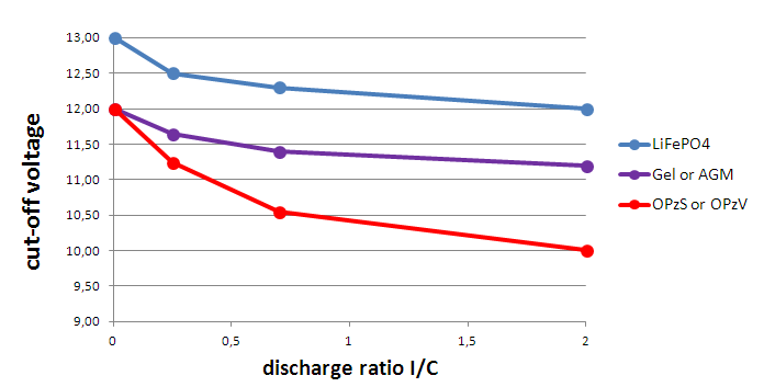 |
Discharge ratio versus battery voltage graph for different battery types
Important
Do not use the "Dynamic cut off" feature in an installation that also has other loads connected to the same battery. In these systems the battery voltage might drop because of other loads connected to the battery. The dynamic cut off algorithm in the inverter can not take those other loads into consideration and will shut down the Inverter too early with an under voltage alarm.
VictronConnect settings
The "Dynamic cut off" feature is disabled by default.
Enable the "Dynamic cut off" feature to use and configure it.
Select the battery type. Choose between: OPzV/OPzS, GEL/AGM, LiFePO4 or Custom.
Enter the battery capacity.
Enter the voltage for the various discharge currents. These values have already been set to the generic voltages that belong to the specific battery type that was selected earlier. Change these settings only in case they need adjustment and you know what you are doing, or in case a custom battery is being used.
 |
VictronConnect app showing the "Dynamic cut off" settings
4.4. Battery settings
 |
Max charge current
This setting sets the maximum battery charge current. It is by default set to the maximum solar charge current.
Use this setting to reduce the charge current, for example, when a smaller battery bank is used that requires a lower charge current.
Battery preset
This setting sets the battery charge algorithm.
A selection can be made between:
Pre-defined factory battery presets
User-defined battery presets
Create, modify or delete a user-defined preset.
This setting uses factory pre-defined presets for a large variety of battery types. These pre-defined charge algorithms are suitable for almost all installations.
It is possible to also create user-defined battery presets. The chapter Customize battery charge algorithm explains how to do this. These user-defined presets are stored in the VictronConnect app library. This is helpful in case multiple solar chargers need to be configured, eliminating the need to define the entire charge algorithm each time a new solar charger is configured.
Expert mode
This setting enables or disables expert mode. It is by default set to "disabled".
Caution
The default charge algorithms work well for almost all installations. Only enable expert settings if your equipment has special requirements.
When this setting is enabled the following parameters can be configured:
Charger voltages: bulk, absorption and float
Bulk: re-bulk voltage offset
Absorption: duration, time and tail current
Equalization: current, interval, stop mode and duration
Temperature voltage compensation
Low temperature cut off
For the meaning of these parameters see chapter Battery charge algorithm settings
Equalization
Caution
Equalization can cause damage to the battery if the battery is not suitable for an equalization charge. Always check with the battery manufacturer prior to enabling equalization.
This setting can be used to disable or enable automatic equalization. When enabled, the number of days can be selected when equalization should repeat.
A manual equalization can be initiated by pressing the "START NOW" button. Use the manual equalize option only during absorption and float charge stages, and when there is sufficient sunlight. The current and voltage limits are identical to the automatic equalize function. The manual equalization stage lasts 1 hour and can be stopped at any time by the Stop Equalize.
Notice
The equalization setting might not be active, this can be the case if the battery preset does not support an equalization charge which is the case with lithium batteries.
4.4.1. Battery charge algorithm settings
This chapter explains all parameters that are used in "Expert" mode and the settings that are used when programming a custom battery type via the battery preset menu.
 |
Absorption voltage
This setting sets the absorption voltage.
Adaptive absorption time
This setting enables or disables the adaptive absorption time.
When disabled: The length of the absorption stage is the same each day, the length is determined by the "Maximum absorption time" setting, provided there is enough solar power.
Be aware that this option can potentially result in overcharging your batteries, especially for lead batteries and if only shallow daily discharges take place. Check with the battery manufacturer for the recommended maximum absorption time.
The only condition that can end the absorption time before the maximum time has been reached, is the "tail current" setting. If the absorption time always needs to be the same length, then disable the "Tail current" setting. See more information on the tail current setting further down in this chapter.
When enabled: The length of the absorption stage is different each day, it adapts itself to the state of charge of the battery in the morning at the beginning of the charge cycle.
The maximum "adaptive" absorption time for the day is determined by the battery voltage as measured just before the solar charger begins operation each morning.
Multiplier
x 1
x 2/3
x 1/3
x 1/6
Adaptive absorption time *
6:00 hours
4:00 hours
2:00 hours
1:00 hour
12V system
Vbatt < 11.9V
11.9V < Vbatt < 12.2V
12.2V < Vbatt < 12.6V
Vbatt > 12.6V
24V system
Vbatt < 23.8
23.8 < Vbatt < 12.2V
24.2V < Vbatt < 25.2V
Vbatt > 25.2V
*) The adaptive absorption time is calculated by the multiplier times the "Maximum absorption time" setting. The adaptive absorption times in this table are based on the 6 hour default "Maximum absorption time" setting.
Maximum absorption time
This setting sets the absorption time limit. This setting is only available when programming a custom charge profile.
Enter the maximum time in hours and minutes (hh:mm) the solar charger is allowed to spend in the absorption stage. The maximum time that can be set is 12 hours and 59 minutes.
Float voltage
This setting sets the float voltage.
Re-bulk voltage offset
This setting sets the re-bulk voltage offset. This offset voltage is used to determine when a charge stage stops and the bulk stage starts again, i.e. the charge cycle resets and starts at the first charge stage again.
The re-bulk voltage is calculated by adding the re-bulk voltage offset to the lowest voltage setting (normally this is the float stage).
An example: If the re-bulk offset is set at 0.1V and the float voltage at 13.8V, the charge cycle will restart once the battery voltage drops below 13.7V (13.8 minus 0.1) for one minute.
Equalization voltage
This setting set the equalization voltage.
Equalization current percentage
This setting sets the percentage of the "maximum charge current" setting that will be used to calculate the equalization charge current.
For example: If the "maximum charge current" setting is set at 10A and the "Equalization current percentage" setting is set to 10%, the Equalization current will be 1A (10% of 10A).
Automatic equalization
This setting sets the repeat interval when the equalization stage should take place. This can be set between 1 and 250 days. Setting to 1 means a daily equalization, 2 means every other day and so on.
An equalization stage is typically used to balance the cells and also to prevent stratification of the electrolyte in flooded lead-acid batteries. If equalization is needed or not depends on the type of battery if (automatic) equalization is needed and under what conditions. Check with the battery supplier to find out if equalization is needed for the battery.
During the equalization stage, the charge voltage increases up to the set "Equalization voltage". This is maintained as long as the charge current stays below the "equalization current percentage" setting of the "Maximum current" setting.
Duration of the Automatic equalization cycle:
For all VRLA battery presets and for some flooded battery presets, the automatic equalization stage ends when the voltage limit (maxV) has been reached.
For the lithium battery preset, equalization is not available.
When an automatic equalization stage has not been completed within one day, it will not resume the next day. The next equalization surge will take place according to the interval as set in the "Auto Equalization" setting.
Equalisation stop mode
This setting determines when the equalisation stage should end:
Automatic: Equalization stops if the battery voltage has reached the equalisation voltage
Fixed time: Equalization stops when the time has reached the time as set in the "Maximum equalization duration" setting.
Maximum equalization duration
This setting sets the maximum time that the equalization stage will last.
Manual equalization
Use this to perform a "once-off" equalization. Once the "start now" button is pressed, a one-hour equalization cycle will be performed, alternatively, the equalization stage can be stopped manually.
Tail current
This setting sets the current threshold to end the absorption stage before the maximum absorption time has been reached. If the charge current drops below the set tail current, for one minute, the absorption stage will end and the float stage will start. This setting can be disabled by setting it to zero.
Temperature compensation
This setting sets the temperature compensation coefficient that is needed for temperature compensated charging.
Many battery types require a lower charge voltage in warm operating conditions and a higher charge voltage in cold operating conditions. The configured coefficient is in mV per degree Celsius for the whole battery bank, not per cell. The base temperature for the compensation is 25°C (77°F).
The chart below indicates the absorption and float charge voltage behaviour at different temperatures. The graph displays the temperature compensation for a 12V system and uses a -16mV/°C temperature compensation coefficient. For a 24V system multiply the voltages by 2.
 |
Temperature compensated charge graph
By default, the SUN Inverter uses its internal temperature for battery temperature compensated charging. An internal temperature reading is taken in the morning and then again when the e SUN Inverter has been idle for at least one hour, for example when the charger is not actively charging a battery or supplying a load.
When the SUN Inverter is part of VE.Smart Networking and receives a battery temperature reading from a Battery Sense or a battery monitor with a temperature sensor, the actual battery temperature will be used for temperature compensated charging throughout the day.
Low temperature cut-off
This setting is used to prevent damage to a lithium battery by disabling charging at low temperatures.
Warning
The "Low temperature cut-off" feature is only active when a temperature sensor is connected. See the Temperature sensor chapter for more information.
The "low temperature cut-off" setting is by default disabled. When enabled, a low cut off temperature can be set. The default temperature is 5°C, this is a suitable temperature setting for lithium iron phosphate (LFP) batteries. However, always check with the lithium battery supplier to find out what this temperature should be set at.
The "low temperature cut-off" mechanism will stop battery charging when the battery temperature has dropped below the low temperature cut-off setting. Battery charging will resume once the battery temperature has risen 0.5°C above the low temperature cut-off setting.
Note that setting "low temperature cut-off" is not needed for Victron Lithium Smart batteries or for Victron Super Pack batteries with serial number HQ2040 and above. This setting is only needed for lithim batteries that are unable to block charging when the temperature drops too low.
4.5. VE.Smart Networking
 |
The VE.Smart Networking allows a variety of products connected to the same network to share data via Bluetooth. The VE.Smart Networking is especially designed for smaller systems that do not have a GX device installed.
When this product is part of a VE.Smart Networking it can receive data or communicate with the following devices:
All SmartSolar solar chargers
All BlueSolar solar chargers that are connected to a VE.Direct Bluetooth Smart dongle.
A BMV or SmartShunt battery monitor equipped with Bluetooth (or VE.Direct Bluetooth Smart dongle) and a optional BMV temperature sensor.
Certain AC chargers
SUN inverter
For the product compatibility list see the VE.Smart manual located on the VictronConnect app product page.
The VE.Smart Networking can be used for:
Temperature sensing - the measured battery temperature is used by the chargers in the network for temperature compensated charging and in case of lithium battery for the low temperature cut off.
Battery voltage sensing - the measured battery voltage is used by the chargers in the network to to compensate the charge voltage should there be a voltage drop over the battery cables.
Current sensing - The measured battery current is used by the charger so it knows the exact tail current at which the absorption stage should end and the float (or equalisation) stage should start. To measure the charge current all charge currents from all chargers are combined, or if a battery monitor is part of the network the actual battery current will be used.
Synchronised charging - All chargers in the network will act as they were one large charger. One of the chargers in the network will assume a master role and the master will dictate the charge algorithm the other chargers will be using. All chargers will follow the same charge algorithm and charge stages. The master is selected randomly (not user settable) so it is important that all chargers use the same charge settings. During synchronised charging each charger will charge up to its own maximum charge current setting (it is not possible to set a maximum current for the whole network). For more information see the VE.Smart manual located on the VictronConnect app product page.
This video introduces the Smart Battery Sense and some features of the VE.Smart Networking:
4.5.1. VE.Smart Networking setup
VE.Smart Networking design notes:
There can only be one product in the network that transmits battery voltage and/or battery temperature. It is not possible to use a battery monitor together with a Smart Battery Sense, or multiples of these devices.
For the network to be operational all networked devices must be within Bluetooth transmission distance of each other.
A maximum of 10 devices can be joined into a VE.Smart Networking.
Some older devices might not support VE.Smart Networking. for more information see the Limitations chapter in the VE.Smart Networking manual.
Setting up the network
When setting up the network, first set up the Smart Battery Sense or battery monitor, and then add one or more solar chargers or AC chargers to the network.
All solar chargers and AC chargers need to have the same charge settings. The easiest way to do this is to use a preset battery type or a saved used defined battery type. A warning #66 message will be shown if there is a difference between the devices charge settings.
To set up a new network:
Open the VictronConnect app.
Select one of the devices that needs to become part of the new VE.Direct network.
Navigate to the settings page by clicking the gear
 symbol.
click on "VE.Smart networking".
Click on "create network".
Enter a name for the new network.
Click "save".
Wait for confirmation that the network has been set up and click "OK".
If more devices need to be added to this network go to next paragraph and join multiple devices to the network.
To join another device to an existing network:
Open the VictronConnect app. Select a device that needs to become part of a VE.Direct network.
Navigate to the settings page by clicking the gear
symbol.Click on "VE.Smart Networking".
Click on "join existing".
Select the network the device needs to be joined to.
Wait for confirmation that the network has been set up and click "OK".
Repeat above steps if more devices need to be added to the network.
To leave a network:
Open the VictronConnect app.
Select a device that needs to be removed from the VE.Direct network.
Navigate to the settings page by clicking the gear
symbol.Click on "VE.Smart Networking".
Click on "leave network".
Check the network
Once the network has been set up all devices communicate with each other. The active LED on each connected device will now blink every 4 seconds. This is an indication that the device is actively communicating with the network.
To check if an individual device is communicating with the network, click on the VE.Smart symbol  in the main screen next to the solar dail. A pop-up window will open showing the connection status and the shared parameters.
 |
VE.Smart Networking pop-up
To check if all devices are actively communicating with the same VE.Smart Networking, navigate to the settings page of one of the networked devices and click on "VE.Smart Networking". A screen will be shown containing which device parameters of this device are shared and all the other devices that are connected to the same network are shown.
 |
Example of a VE.Smart Networking
More information
For more information see the VE.Smart Networking manual.
4.6. Firmware update
The firmware can be updated in the inverter product settings:
Navigate to the inverter settings by clicking on the cog
symbol in the right top corner.Click on the 3 dot
 symbol in the right top corner.
Choose "Product settings" from the menu.
The firmware section will display the firmware version and a button to perform a firmware update.
4.7. Reset settings to default
The inverter settings can be set to default in the following way:
Navigate to the inverter settings by clicking on the cog
symbol in the right top corner.Click on the 3 dot
symbol in the right top corner.Select "Reset to defaults" from the menu and the settings will reset to default.