7. Appendix
7.1. AC outlet
The inverter is equipped with an IEC-320 outlet.
AC outlet | AC voltage | Image |
|---|---|---|
IEC-320 (male plug included) | 230V | 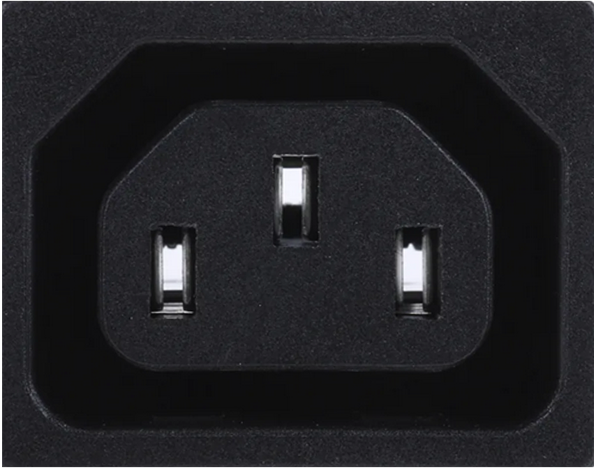 |
7.2. Connection overview
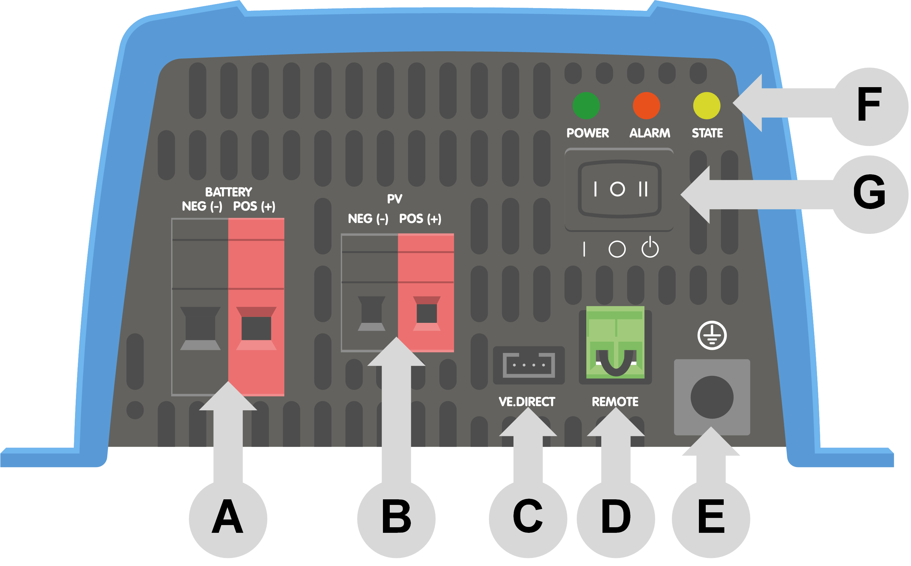
# | Description |
|---|---|
A | Battery connections |
B | PV connections |
C | VE.Direct connection |
D | Remote on/off terminal connection |
E | Chassis ground connection |
F | LEDs |
G | ON/OFF/CHARGER switch |
7.3. Installation information neutral to ground connection
Connecting the inverter neutral output to the chassis/ground
The AC output is isolated from the DC input and the chassis. Local regulations may require a true neutral. In this case one of the AC output wires must be connected to the chassis, and the chassis must be connected to a reliable ground. Inside the inverter a provision has been made to be able to connect the neutral and the chassis; the way to do this is explained below.
Please be sure to disconnect the battery when connecting the neutral to protective earth (PE).
An internal PE wire, which is used to connect the neutral and the chassis, is accessible after removing the plastic cover. A Torx T10 screwdriver is needed to loosen the four screws which hold the plastic cover.
In the pictures below the two possible connections of the PE wire are shown:
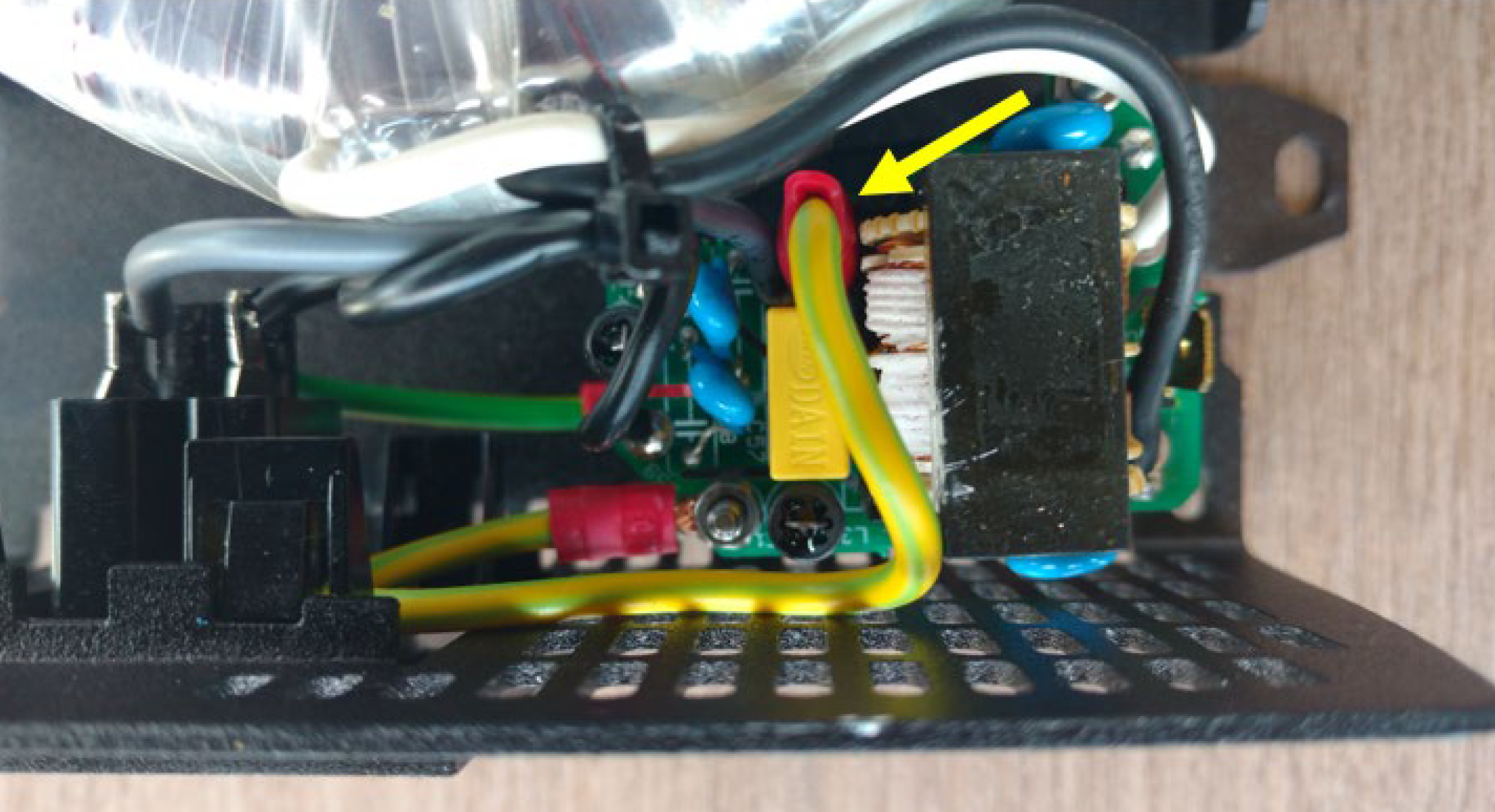
Neutral floating
Position of the PE wire (indicated by the arrow):
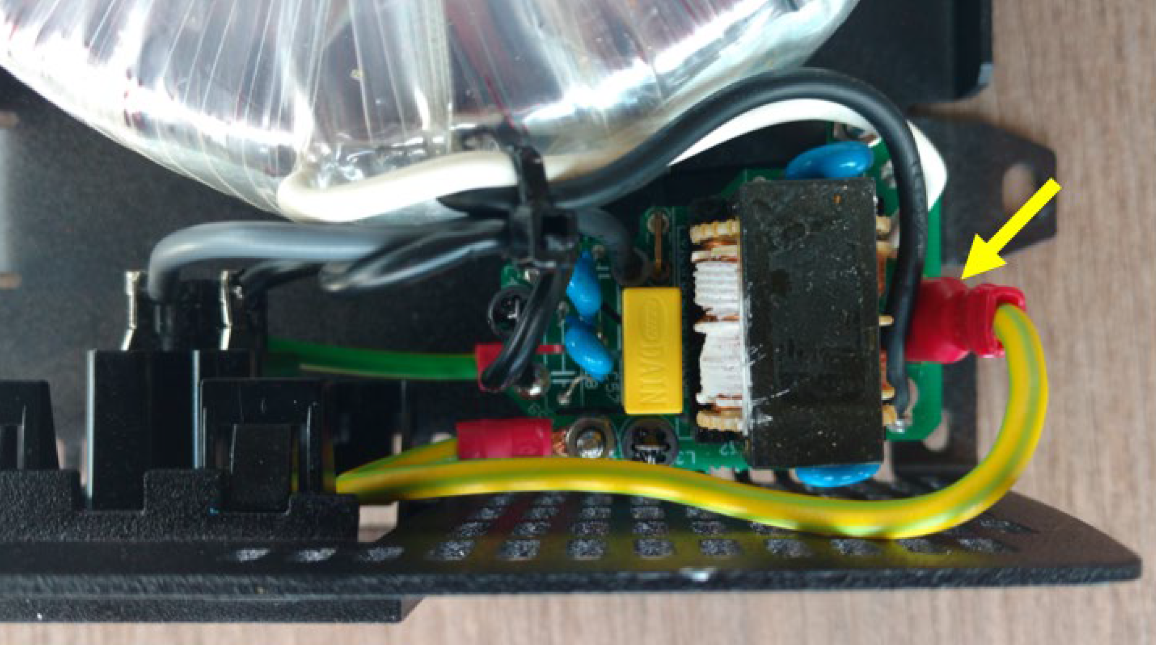
Neutral connected to protective earth
Position of the PE wire (indicated by the arrow):
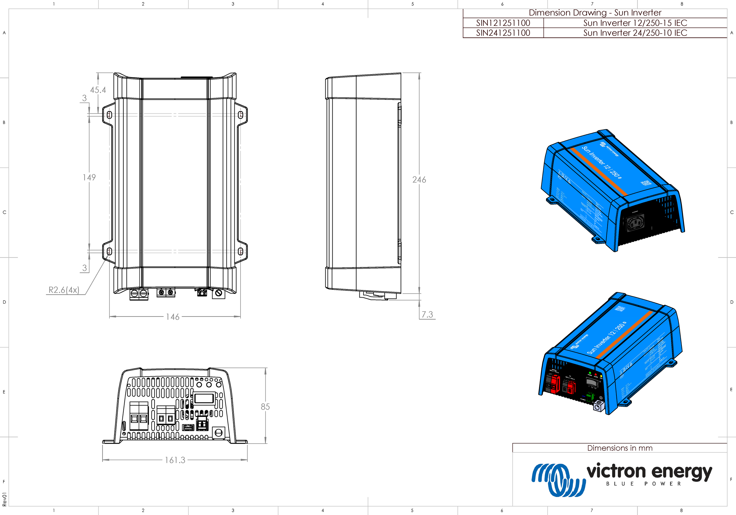
7.4. Dimensions