4. Operation
4.1. Startup and shutdown procedure
Note: This presumes the correct installation procedure has been followed, and battery and PV polarity was tested and confirmed to be correct by the installer. These polarity tests are essential as part of installation, but should not be necessary as part of the normal start up and shut down procedure.
4.1.1. Startup
Quickly connect the DC side load breaking fuse or isolation to provide DC power to the battery terminals of the unit.
Switch on PV array connection to the unit.
Switch on the unit using the on/off switch located on the bottom left hand underside of case, switch toward yourself for ON position.
When powering up, the screen will display the product details, firmware version, and if any start up errors are detected.
Operation will then commence (if correctly configured).
4.1.2. Shutdown
Switch off the unit using the on/off switch located on the bottom left hand underside of the case. Switch away from yourself for OFF position.
Switch off the PV array connection to the unit.
Quickly disconnect the DC side load breaking fuse or isolation providing DC power to the battery terminals.
Note: dangerous residual voltages may still exist inside the product and at the terminals after shutdown. Never open the product casing, or touch bare terminals.
4.2. Device display
The unit has an LCD screen that displays operational information. The screen cycles through the relevant displays every few seconds.
Startup Screen
When the units is first switched on it will display firmware, serial number and model details for severals while the unit performs self tests.
Battery:
Battery Power, Current, DC voltage, Temperature (*). Battery state (e.g. discharging, bulk, absorption, float, etc).
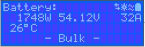
(*) These items are only visible if the data is available.
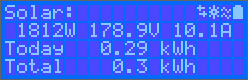
Solar 1
Solar Power, Voltage and Current, kWh daily and total Yield.
Additional MPPT Solar Trackers
Additional solar trackers will display the same values as above where available on additional screens.
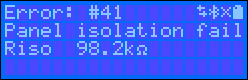
Errors, Warnings and Alarms
The system will display code notifications as required. See troubleshooting section for additional information.
In the top right of the display are other system information icons.
Communicating on any interface (e.g., Bluetooth, VE.Can, etc.) | |
Bluetooth Enabled, Icon colour changes when connected | |
MPPT Active | |
(Blinking) Error or Warning | |
Battery, fill corresponds with voltage, blinks when empty |
4.3. STATUS - Live Data Information
MPPT [Model Number] confirms the connected device. A custom name can also be set if desired.
Solar 'Gauge' icon shows the dynamic real-time power output from the solar array. With regard to the Solar Panel voltage, note that the Solar charger will only operate once the Panel voltage has risen more than 5V above battery voltage.
Battery - Voltage The voltage measurement is taken at the battery terminals of the Solar charger.
Battery - Current This reading shows the current flowing-to, or drawn-from the battery terminals of the Solar charger. Note that in the case of the 100/20 Solar chargers and smaller - which have a dedicated load output - a Positive notation alongside the current reading means that current is flowing to the battery; whereas a Negative notation means that current is being drawn from the battery.
Battery - State:
Bulk: During this stage the Controller delivers as much charge current as possible to rapidly charge the batteries. When the battery voltage reaches the Absorption voltage setting, the Controller activates the Absorption stage.
Absorption: During this stage the Controller switches to the constant voltage mode, where a pre-set absorption voltage, suitable to the battery type (See section 4.1 Battery Settings below), is applied. When the charge current decreases below the Tail current and/or the pre-set Absorption time has elapsed, the battery is fully charged. The Controller switches to the Float stage. The Tail current is 1A for models 100/20 and smaller; and 2A for larger models. (When an automatic equalisation is being performed this will also be reported as 'Absorption'.)
Float: During this stage the float voltage is applied to the battery to maintain a fully-charged state. When the battery voltage drops below float voltage during at least 1 minute, a new charge cycle will be triggered.
Equalization: This is shown when 'Start equalization now' is pressed in the battery settings. The charger applies the equalization voltage to the battery as long as the current level stays below 8% (Gel or AGM) or 25% (tubular plate) of the bulk current.
* Menu items only available on MPPT models with load output (100/20 and smaller.)
Load output on/off The function of the load output switch is to disconnect the load when the battery is low on power in order to avoid damaging it. See the configuration section (4.2 below) for available load switching algorithms.
Load current This shows the current being drawn by electronic devices, lights, fridge, etc.
Note that for the load output reading to be reliable, all loads must be wired directly to the load output …including their negative terminals. See manual or consult your installer for details.
Note that some loads (especially inverters) are best connected directly to the battery. In such cases the load output does not show a reliable reading - the current drawn by the inverter, for example, will not be included. Consider adding a BMV battery monitor which will measure all current going to - or being drawn from the battery, including loads connected directly to the battery …not just the load output terminals of the charge controller.
Is my battery being charged?
The battery will be charged whenever the power available from the PV panels exceeds the power being drawn by the loads (lights, fridge, inverter, etc.).
You can only tell if that is the case with Charge Controllers which have all loads connected to the load output terminals. Remember: any loads connected directly to the battery can't be monitored by the Solar Charger.
4.4. History - Thirty-day graphic
(The fragmented square icon (top left) allows you to toggle between 'portrait' and 'landscape' screen presentations.)
A summary of activity for the last 30 days is presented graphically. Swipe the bar left or right to show any of the previous 30 days.
The daily log shows:
Yield: The energy converted for that day.
P max: The maximum power recorded during the day.
V max: The highest voltage from the PV array during the day.
Clicking on any day/bar in the graph will expand the information to show charge-status times - both as hrs/m; and also as a percentage of the 'charge' day. This graphic provides an at-a-glance representation of how much time your charger is spending in each of three modes: Bulk / Absorption / Float.
Tip! You can use the charge times to see if the PV array is properly sized for your requirements. A system which never reaches 'Float' may need more panels; or perhaps the load could be reduced?
It is possible to export the history as a comma separated file (.csv) by clicking the three connected dots at the top right of the history screen:
This is an example of the exported data for 3 of 30 days:
Battery Voltage
The first figure shows the maximum battery voltage for the day …the figure below is the minimum battery voltage.
Errors
Shows the number of errors (if any) for the day, to see the error codes click on the orange point. See MPPT Solar Charger Error Codes. (You may need to slide the display on your device up to see the errors.)
Total
This shows the total energy converted by the installation and is not re-settable.
Since Cleared
This shows how much energy has been converted by the installation since the last reset.
4.5. Protections and automatic restarts
4.5.1. High battery voltage
Reduce DC input voltage and/or check for a faulty battery- or solar-charger in the system. After shutting down due to a high battery voltage, the unit will first wait 30 seconds and then retry operation as soon as the battery voltage has dropped to acceptable level.
4.5.2. High temperature
A high ambient temperature or enduring high charge current may result in MPPT reducing output and eventually shutting down to over temperature. The MPPT will resume once the temperature falls to within specification.
4.6. Maintenance
The solar charger does not need regular maintenance. Unqualified users should not attempt to open the product casing.