3. Installation
3.1. Location of the MPPT
 | To ensure a trouble free operation of the SmartSolar MPPT RS, it must be used in locations that meet the following requirements: a) Avoid any contact with water. Do not expose the product to rain or moisture. b) Install the SmartSolar MPPT RS upright and vertical. Ensure 30cm clearance above and below it. c) The SmartSolar MPPT RS must be installed on a non-flammable surface and the construction materials surrounding the installation should also be non-flammable. d) Do not place the unit in direct sunlight. Ambient air temperature should be between -40°C and 60°C (humidity < 95% non-condensing). e) Do not install the SmartSolar MPPT RS in an environment where the air could be contaminated with particulate matter such as soot, dust or salt. For example conductive soot from the exhaust of a diesel generator could be drawn into the unit and cause short circuits inside it. f) Do not install the SmartSolar MPPT RS where flammable or corrosive gases or vapours could come near the installation. g) Do not obstruct the airflow around the SmartSolar MPPT RS. h) If the SmartSolar MPPT RS is installed in an area used for general storage, ensure that no flammable materials such a cardboard boxes are stored close to the installation. Ensure that the end user is aware of these requirements. Figure 1. Thermal image of MPPT RS heat zones required for clearance. 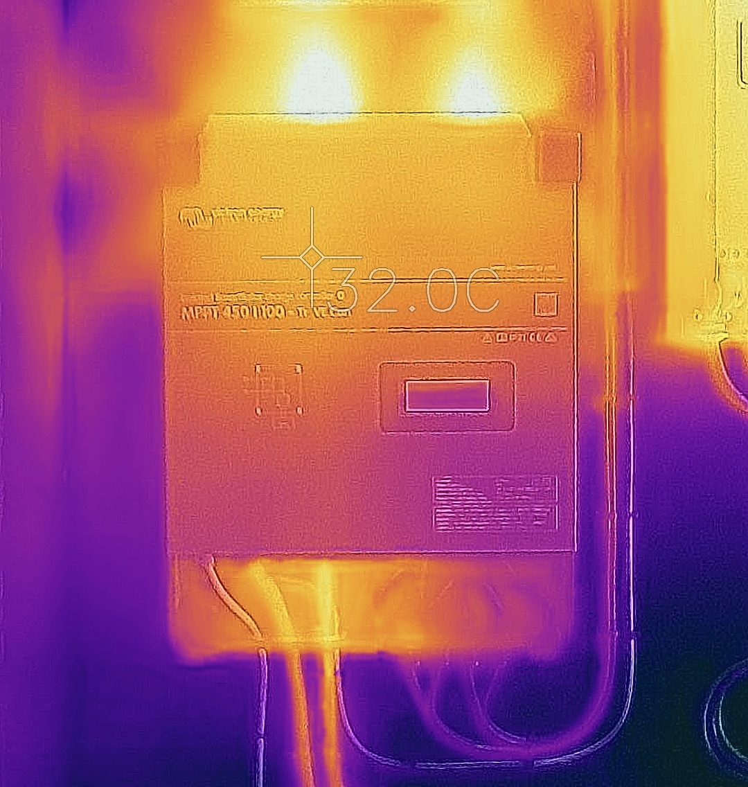 |
 | This product contains potentially dangerous voltages. It should only be installed under the supervision of a suitable qualified installer with the appropriate training, and subject to local requirements. Please contact Victron Energy for further information or necessary training. |
| Excessively high ambient temperature will result in the following: · Reduced service life. · Reduced charging current. · Reduced peak capacity, or shutdown of the MPPT. Never position the appliance directly above lead-acid batteries. The MPPT RS is suitable for wall mounting. For mounting purposes, a hook and two holes are provided at the back of the casing. The device must be fitted vertically for optimal cooling. |
| For safety purposes, this product should be installed in a heat-resistant environment. You should prevent the presence of e.g. chemicals, synthetic components, curtains or other textiles, etc., in the immediate vicinity. |
ImportantTry and keep the distance between the product and the battery to a minimum in order to minimise cable voltage losses | |
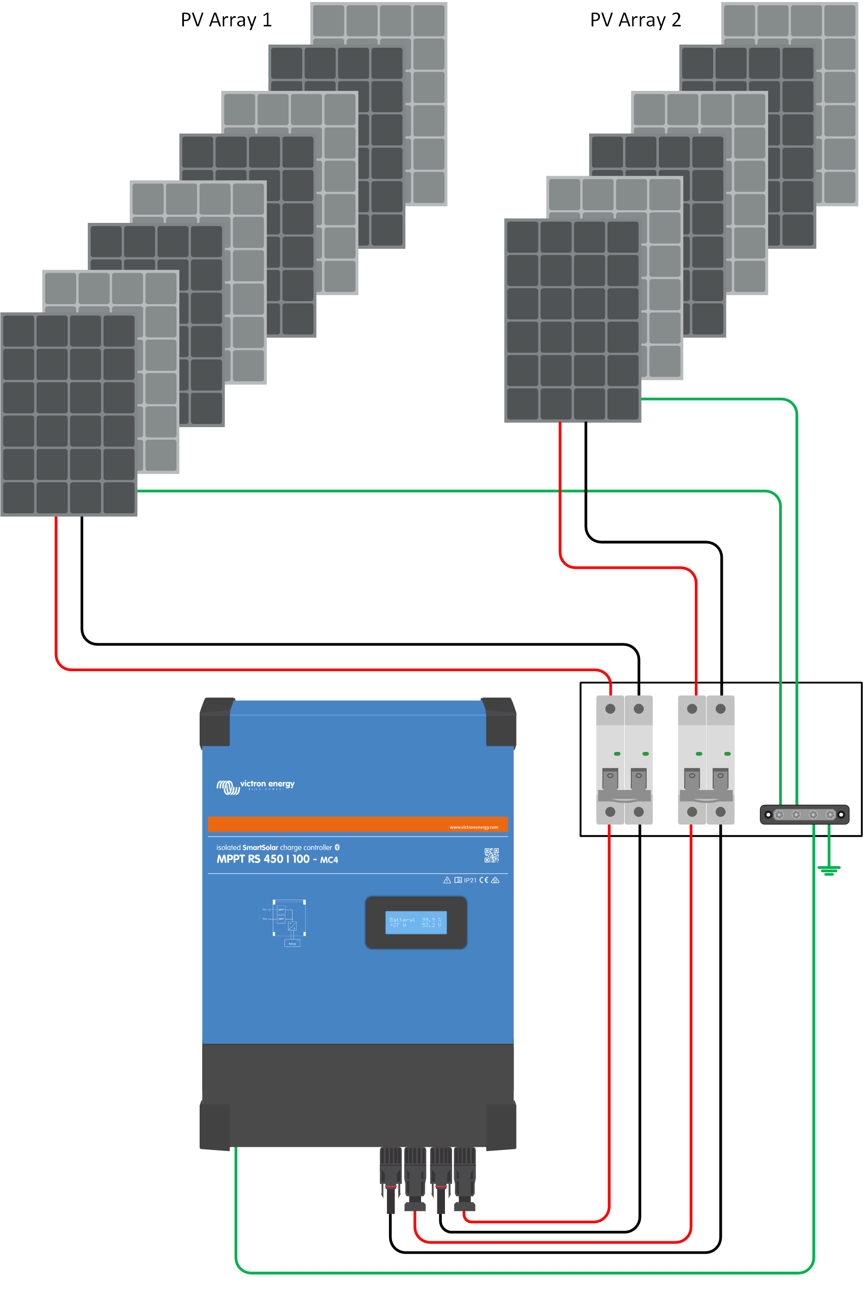
3.2. MPPT grounding, detection of PV array insulation faults & Earth fault alarm notification
The SmartSolar MPPT RS will test for sufficient resistive isolation between PV+ and GND, as well as PV- and GND. If the resistance falls below the threshold, the unit will report an error and send an error signal to the GX device (if connected) for audible and email notifications. Despite the error, the product will continue charging the battery.
If an audible alarm and/or email notification of this fault is required, then you must also connect a GX device (such as the Cerbo GX). Email notifications require an internet connection to the GX device and a properly configured VRM account.
The positive and negative conductors of the PV array must be isolated from ground.
Ground the frame of the PV array according to local regulations. Use the ground lug on the chassis to connect the unit to the common earth.
The grounding conductor from the chassis ground lug to the earth must have a cross-section at least equal to that of the PV array conductors.
When a PV resistance isolation fault is indicated, do not touch any metal parts. Contact a qualified technician immediately to inspect the system for faults.
The battery terminals are galvanically isolated from the PV array, ensuring that PV array voltages cannot transfer to the battery side of the system in the event of a fault.
3.3. Battery and battery lead requirements
In order to utilize the full capacity of the product, batteries with sufficient capacity and battery cables with sufficient cross section should be used. The use of undersized batteries or battery cables will lead to:
Reduction in system efficiency.
Unwanted system alarms or shutdowns.
Permanent damage to system.
See table for MINIMUM battery and cable requirements.
Model | 450/100 | 450/200 | |
|---|---|---|---|
Battery capacity lead-acid | 200 Ah | 400 Ah | |
Battery capacity lithium | 50 Ah | 100 Ah | |
Recommended DC fuse | 125 A - 150 A | 250 A | |
Minimum cross section (mm2) per + and - connection terminal | 0 - 2 m | 35 mm2 | 70 mm2 |
2 - 5 m | 70 mm 2 | 2 x 70 mm 2 |
Warning
Consult battery manufacture recommendations to ensure the batteries can take the total charge current of the system. Decision on battery sizing should be made in consultation with your system designer.
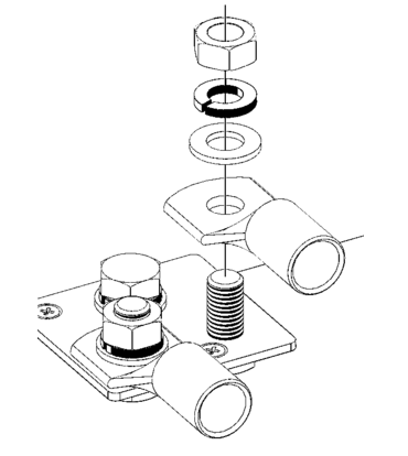
| Use a torque wrench with insulated box spanner in order to avoid shorting the battery. Maximum torque: 14 Nm Avoid shorting the battery cables. |
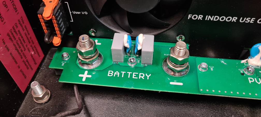
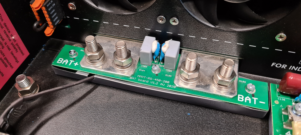
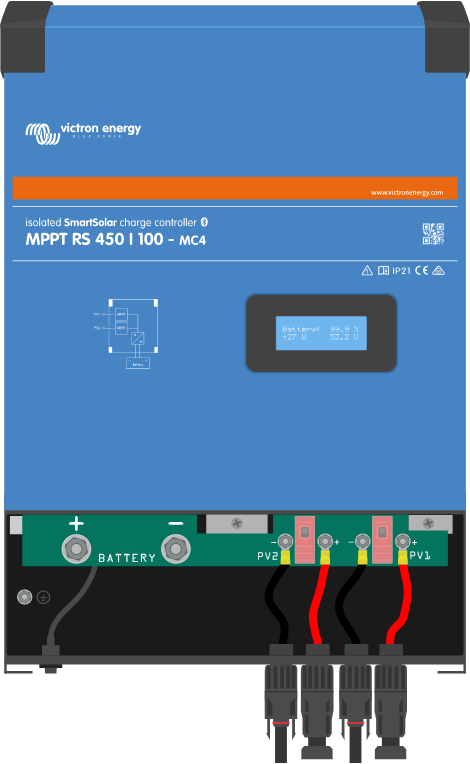
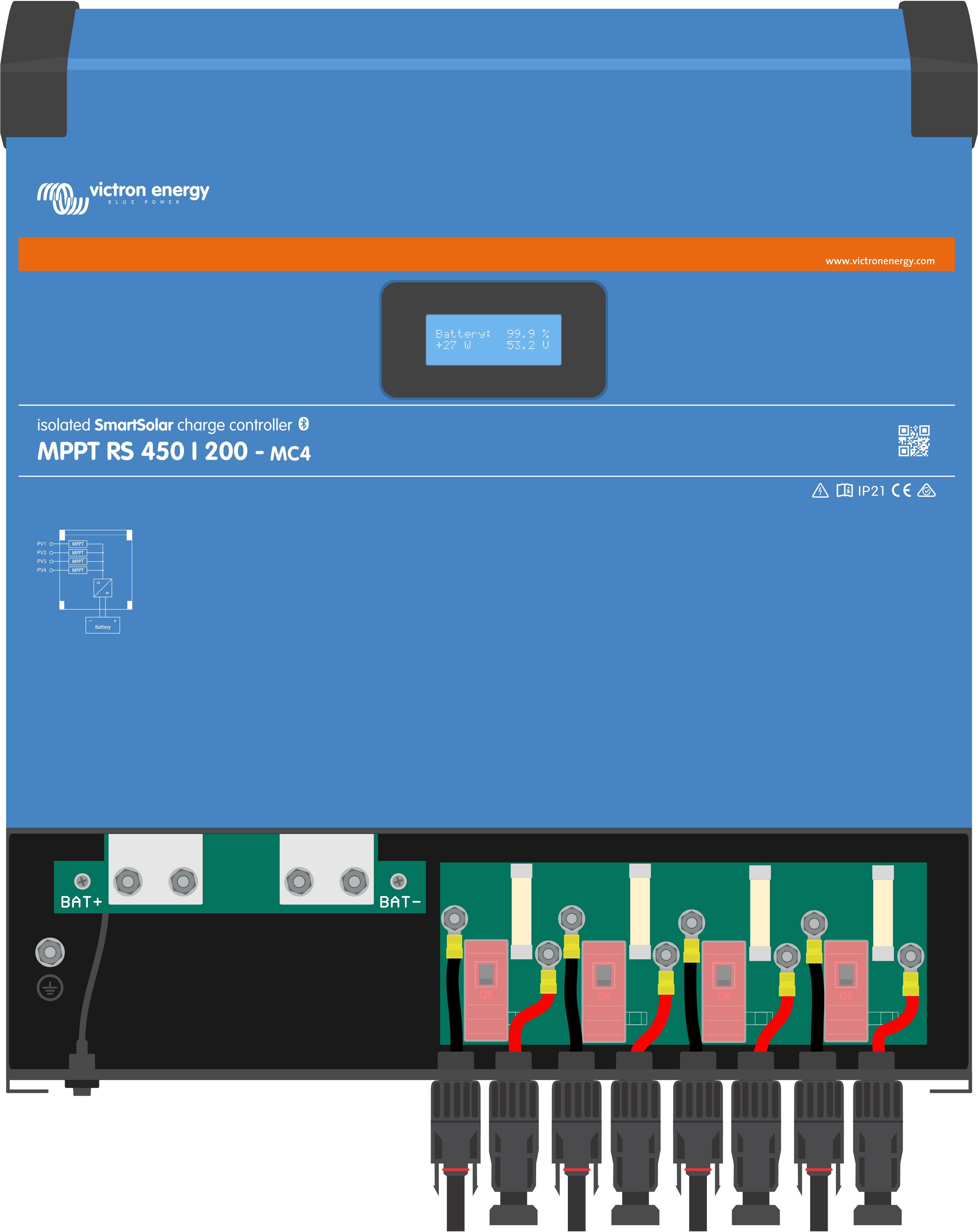
To access the battery terminals, undo the two screws at the bottom of the enclosure and remove the cover to expose the service compartment.
|
| |
|
|
|
|
3.4. Solar input wiring
The SmartSolar MPPT RS is not fitted with a PV disconnect switch. An appropriately rated DC disconnection swich must be installed between the PV array and the SmartSolar MPPT RS.
Mount the PV disconnection switch in a readily accessible location.
Warning
Ensure that the DC disconnection switch is properly rated for at least 450V DC. The disconnect switch MUST be rated for DC applications and be rated for at least the expected PV array short circuit current.
Do not use switches rated only for AC circuits.
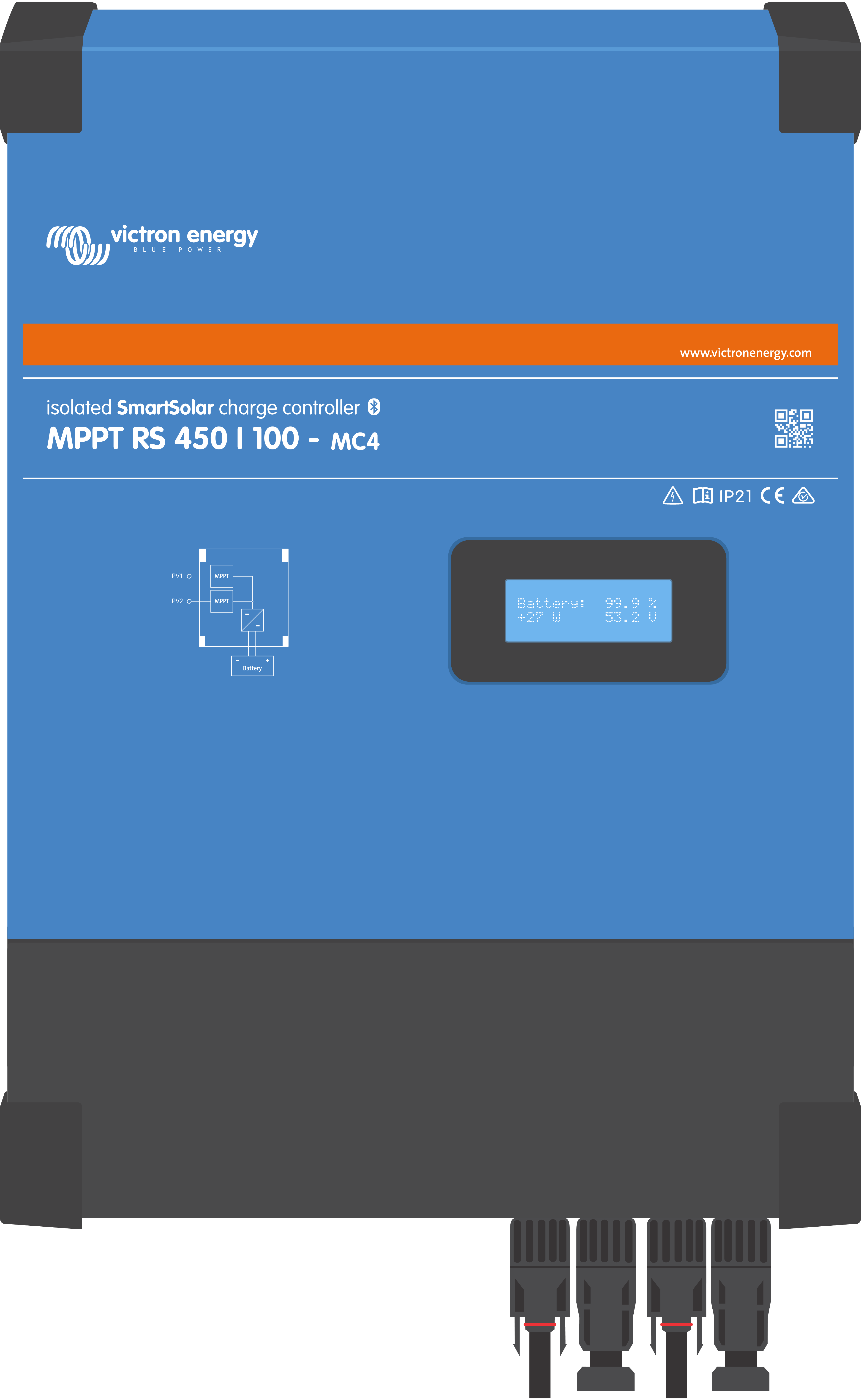
The MPPT RS 450/100 and the MPPT RS 450/200 Solar charge controllers feature MC4 connectors located on the bottom of the unit. These connectors are pre-wired, so the bottom cover does not need to be removed to connect the PV cables.
The MPPT 450/100 is equipped with two pairs of MC4 connectors, one male and one female per tracker.
|
|
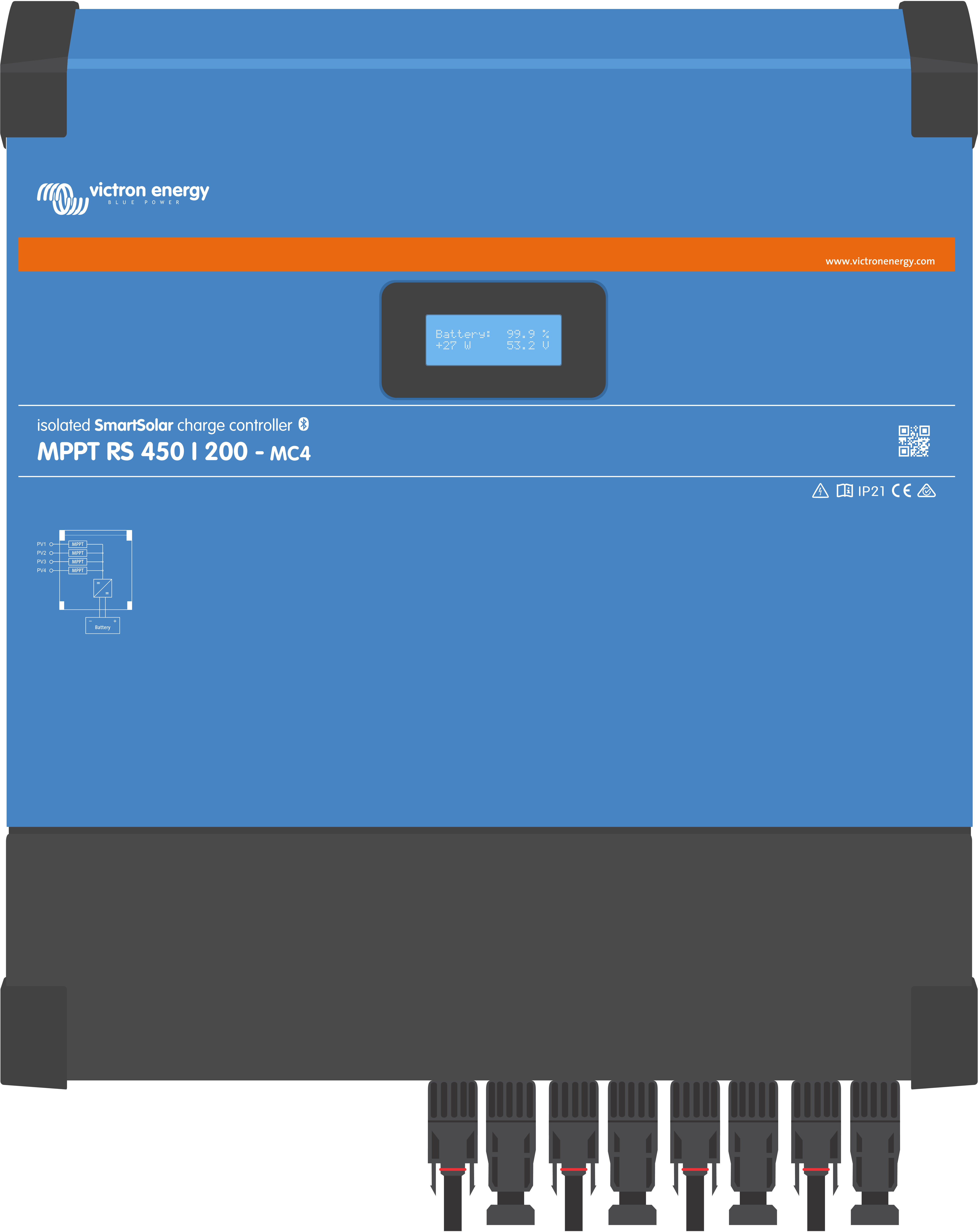
The MPPT 450/200 is equipped with four pairs of MC4 connectors, one male and one female per tracker.
|
|
3.5. Solar array configuration
The MPPT RS must keep the individual tracker inputs isolated from each other. That means one solar PV array per input, do not attempt to connect the same array to multiple tracker inputs.
Warning
Always use genuine Staubli MC4 connectors for the PV connections to the SmartSolar MPPT RS.
Connectors from other brands may not be fully compatible with the Staubli connectors on the SmartSolar MPPT RS.
The SmartSolar MPPT RS is built using Staubli MC4 connectors. There are many other brands available, but some manufacturing variations mean that they may make poor contact and cause excessive heat. There are also inferior brands on the market which will likely cause problems.
Warning
The maximum rated voltage of the solar charger is 450 V. A PV overvoltage event will damage the solar charger. This damage is not covered by warranty.
In case the PV array is located in colder climates the PV array can output more than its rated Voc. Use the MPPT sizing calculator on the solar charger product page to calculate this variable. As a rule of thumb, keep an additional 10% safety margin.
The maximum operational input current for each tracker is 16 A.
MPPT PV inputs are protected against reverse polarity, to a maximum short circuit current of 20 A for each tracker.
Connecting PV arrays with a higher short circuit current is possible, up to an absolute maximum of 30A, as long as connected with correct polarity. This outside of specification potential allows for system designers to connect larger arrays, and can be useful to understand in case a certain panel configuration results in a short circuit current just slightly above the maximum of the reverse polarity protection circuit.
Solar PV input cable insulation should be removed to allow 12 mm of exposed copper into the PV attachment point on the MPPT. It should not be possible to come into contact with any exposed copper wiring, the fit must be clean without any stray strands.
Warning
BEWARE that the product warranty will be void if a PV array with a short circuit current larger than 20 A array is connected in reverse polarity.
Caution
The MPPT RS must keep the individual tracker inputs isolated from each other. That means one solar PV array per input, do not attempt to connect the same array to multiple tracker inputs.
When the MPPT switches to float stage it reduces battery charge current by increasing the PV Power Point voltage.
The maximum open circuit voltage of the PV array must be less than 8 times the minimum battery voltage when at float.
For example, where a battery has a float voltage of 54.0 volts, the maximum open circuit voltage of the connected array cannot exceed 432 volts.
Where the array voltage exceeds this parameter the system will give a "Over-charge Protection" error and shut down.
To correct this, either increase the battery float voltage, or reduce PV voltage by removing PV panels from the string to bring the voltage back within specification.
3.5.1. MPPT RS example PV configuration
Notice
This is an example of an array configuration. The decision on the specific array configuration, sizing and design for your system should be made in consultation with your system designer.
Panel Type | Voc | Vmpp | Isc | Impp | # of panels | Max String Voltages | Power total per string |
|---|---|---|---|---|---|---|---|
Victron 260W (60 cell) | 36.75 V | 30 V | 9.30 A | 8.66 A | # 1 - 11 #2 - 8 | # 1 - 404 V # 2 - 304V | 2850 W 2080 W |
3.6. Cable connection sequence
First: Confirm correct battery polarity, connect the battery.
Second: if required, connect the remote on-off, and programmable relay, and communications cables
Third: Confirm correct PV polarity, and then connect the solar array (if incorrectly connected with reverse polarity, the PV voltage will drop, the controller will heat up but will not charge the the battery).
3.7. Synchronised parallel operation
Several charge controllers can be synchronised with the CAN interface. This is achieved by simply interconnecting the chargers with RJ45 UTP cables (bus terminators needed, see section 3.6).
The paralleled charge controllers must have identical settings (e.g. charge algorithm). The CAN communication ensures that the controllers will switch simultaneously from one charge state to another (from bulk charge to absorption for example). Each unit will regulate its own output current, depending on the output of each PV array and cable resistance.
In case of synchronized parallel operation, the network icon will blink every 3 seconds on all paralleled units.
The PV inputs should not be connected in parallel. Each charge controller must be connected to its own PV array.
3.8. Energy Storage System (ESS)
An Energy Storage System (ESS) is a specific type of power system that integrates a power grid connection with a Victron Inverter/Charger, GX device and battery system. It stores solar energy into your battery during the day for use later on when the sun stops shining.
Please refer to the following manual how to setup an ESS:
3.9. User I/O
3.9.1. Remote on/off connector
The remote on/off connector has two terminals, the “Remote L” and the “Remote H” terminal.
The SmartSolar MPPT RS ships with the remote on/off connector terminals connected to each other via a wire link.
Note that for the remote connector to be operational, the main on/off switch on the solar charger needs to be switched to “on”
The remote on/off connector has two different operational modes:
On/off mode (default):
The default function of the remote on/off connector is to remotely switch the unit on or off.
The unit will switch on if “Remote L” and the “Remote H” are connected to each other (via a remote switch, relay or the wire link).
The unit will switch off if “Remote L” and the “Remote H” are not connected to each other and are free floating.
The unit will switch on if “Remote H” is connected to battery positive (Vcc).
The unit will switch on if “Remote L” is connected to battery negative (GND).
2-wire BMS mode:
This feature can be enabled via VictronConnect. Go to the Battery settings page, and then to “Remote mode”.
Set the remote mode from “on/off” to “2-wire BMS”.
In this mode, the “load”, “load disconnect” or “allowed to discharge” signal and the “charger”, “charger disconnect” or “allowed to charge” signals from a Victron lithium battery BMS are used to control the unit. They respectively turn the inverter off in case discharge is not allowed, and turn the solar charger off if charging is not allowed by the battery.
Connect the BMS “load”, “load disconnect” or “allowed to discharge” terminal to the Inverter RS Smart “Remote H” terminal.
Connect the BMS “charger”, “charge disconnect” or “allowed to charge” to the unit Inverter RS Smart “Remote L” terminal.
3.9.2. Programmable relay
Programmable relay which can be set for general alarm, DC under voltage or genset start/stop function. DC rating: 4A up to 35VDC and 1A up to 70VDC
3.9.3. Voltage sense
For compensating possible cable losses during charging, two sense wires can be connected directly to the battery or to the positive and negative distribution points. Use wire with a cross-section of 0,75mm².
During battery charging, the charger will compensate the voltage drop over the DC cables up to a maximum of 1 Volt (i.e. 1V over the positive connection and 1V over the negative connection). If the voltage drop threatens to become larger than 1V, the charging current is limited in such a way that the voltage drop remains limited to 1V.
3.9.4. Temperature sensor
For temperature-compensated charging, the temperature sensor (supplied with the unit) can be connected. The sensor is isolated and must be fitted to the negative terminal of the battery. The temperature sensor can also be used for low temperature cut-off when charging lithium batteries (configured in VictronConnect).
3.9.5. Programmable analog/digital input ports
The product is equipped with 2 analog/digital input ports, they are labelled AUX_IN1+ and AUX_IN2+ on the removable User I/O terminal block.
The digital inputs are 0-5v, and when a input is pulled to 0v it is registered as 'closed'
These ports can be configured in VictronConnect.
Unused: the aux input has no function.
Safety switch: the device is on when the aux input is active.
You can assign different functions to each aux input. In case the same function is assigned to both aux inputs then they will be treated as an AND function, so both will need to active for the device to recognise the input.
3.9.6. User I/O terminal diagram

User I/O Connector is located on bottom left side of connection area, diagram shows 3 perspectives. Left Side - Top - Right Side
3.9.7. User I/O functions
Number | Connection | Description |
|---|---|---|
1 | Relay_NO | Programmable relay Normally Open connection |
2 | AUX_IN - | Common negative for programmable auxiliary inputs |
3 | AUX_IN1+ | Programmable auxiliary input 1 positive connection |
4 | AUX_IN2+ | Programmable auxiliary input 2 positive connection |
5 | REMOTE_L | Remote on/off connector Low |
6 | REMOTE_H | Remote on/off connector High |
7 | RELAY_NC | Programmable relay Normally Closed connection |
8 | RELAY_COM | Programmable relay common negative |
9 | TSENSE - | Temperature Sensor negative |
10 | TSENSE + | Temperature Sensor positive |
11 | VSENSE - | Voltage Sensor negative |
12 | VSENSE + | Voltage Sensor positive |