2. Description
2.1. Boats, vehicles and other stand-alone applications
The basis of the MultiPlus-II is an extremely powerful sine inverter, battery charger and transfer switch in a compact casing.
Important features:
Automatic and uninterruptible switching
In the event of a supply failure or when the generating set is switched off, the inverter/charger will switch over to inverter operation and take over the supply of the connected devices. This is done so quickly that the operation of computers and other electronic devices is not disturbed (Uninterruptible Power Supply or UPS functionality). This makes the inverter/charger highly suitable as an emergency power system in industrial and telecommunication applications.
Two AC outputs
Besides the usual uninterruptable output (AC-out-1), an auxiliary output (AC-out-2) is available that disconnects its load in the event of battery operation. Example: an electric boiler that is allowed to operate only if the genset is running or shore power is available. There are several applications for AC-out-2.
Please enter “AC-out-2” in the search box on our website and find the latest information about other applications.
Three phase capability
Three units can be configured for three-phase output. Up to 6 sets of three units can be parallel connected to provide 45 kW / 54 kVA inverter power and more than 600 A charging capacity.
PowerControl – maximum use of limited AC power
The inverter/charger can supply a huge charging current. This implies heavy loading of the AC mains or generator. Therefore a maximum current can be set. The inverter/charger then takes other power users into account, and only uses “surplus' current for charging purposes.
PowerAssist – Extended use of generator or shore current: the inverter/charger “co-supply” feature
This feature takes the principle of PowerControl to a further dimension allowing the inverter/charger to supplement the capacity of the alternative source. Where peak power is often required only for a limited period, the inverter/charger will make sure that insufficient AC mains or generator power is immediately compensated for by power from the battery. When the load reduces, the spare power is used to recharge the battery.
Programmable relay
The inverter/charger is equipped with a programmable relay. The relay can be programmed for different applications, for example as a starter relay for a generator.
External current transformer (optional)
When used in a grid-parallel topology the internal current transformer cannot measure the current to or from the mains. In this case an external current transformer is needed to implement PowerControl and PowerAssist. See appendix.
Programmable analogue/digital input/output ports (Aux in 1 and Aux in 2, see appendix)
The inverter/charger is equipped with 2 analogue/digital input/output ports.
These ports can be used for several purposes. One application is communication with the BMS of a lithium-ion battery.
2.2. On-grid and off-grid systems combined with PV
External current transformer (optional)
When used in a grid-parallel topology the internal current transformer cannot measure the current to or from the mains. In this case an external current transformer is needed to implement PowerControl and PowerAssist. See appendix.
Frequency shift
When solar inverters are connected to the output of the inverter/charger, excess solar energy is used to recharge the batteries. Once the absorption voltage is reached, charge current will reduce and excess energy will be fed back into the mains. If mains is not available, the inverter/charger will slightly increase the AC frequency to reduce the output of the solar inverter.
Built-in Battery Monitor
The ideal solution is when the inverter/charger is part of a hybrid system (diesel generator, inverter/chargers, storage battery, and alternative energy). The built-in battery monitor can be set to start and stop the generator:
Start at a preset % discharge level, and/or
start (with a preset delay) at a preset battery voltage, and/or
start (with a preset delay) at a preset load level.
Stop at a preset battery voltage, or
stop (with a preset delay) after the bulk charge phase has been completed, and/or
stop (with a preset delay) at a preset load level.
Autonomous operation when the grid fails
Houses or buildings with solar panels or a combined micro-scale heating and power plant or other sustainable energy sources have a potential autonomous energy supply which can be used for powering essential equipment (central heating pumps, refrigerators, deep freeze units, Internet connections, etc.) during a power failure. A problem is, however, that grid-connected sustainable energy sources drop out as soon as the grid fails. With an inverter/charger and batteries, this problem can be solved: the inverter/charger can replace the grid during a power failure. When sustainable energy sources produce more power than needed, the inverter/charger will use the surplus to charge the batteries; in the event of a shortfall, the inverter/charger will supply additional power from the battery.
Programmable
All settings can be changed with a PC and free-of-charge software, downloadable from our website www.victronenergy.com
2.3. Battery charger
2.3.1. Lead-acid batteries
Adaptive 4-stage charge algorithm: bulk – absorption – float – storage
The microprocessor-driven adaptive battery management system can be adjusted for various types of batteries. The adaptive function automatically adapts the charging process to battery use.
The right amount of charge: variable absorption time
In the event of slight battery discharge, absorption is kept short to prevent overcharging and excessive gas formation. After deep discharging, the absorption time is automatically extended in order to fully charge the battery.
Preventing damage due to excessive gassing: the BatterySafe mode
If, in order to quickly charge a battery, a high charge current in combination with a high absorption voltage has been chosen, damage due to excessive gassing will be prevented by automatically limiting the rate of voltage increase once the gassing voltage has been reached.
Less maintenance and aging when the battery is not in use: the Storage mode
The Storage mode kicks in whenever the battery has not been subjected to discharge during 24 hours. In the Storage mode float voltage is reduced to 2.2V/cell (13.2V for 12V battery) to minimise gassing and corrosion of the positive plates. Once a week the voltage is raised back to the absorption level to ‘equalize’ the battery. This feature prevents stratification of the electrolyte and sulphation, a major cause of early battery failure.
Battery voltage sense: the correct charge voltage
Voltage loss due to cable resistance can be compensated by using the voltage sense facility to measure voltage directly on the DC bus or on the battery terminals.
Battery voltage and temperature compensation
The temperature sensor serves to reduce charging voltage when battery temperature rises. This is particularly important for maintenance-free batteries, which could otherwise dry out by overcharging.
Note
The temperature sensor is not supplied with 48V models.
It can be ordered separately. Order number: ASS000001000
2.3.2. Second charge output for starter battery
The 12V and 24V MultiPlus is equipped with a second charge output intended for maintenance charging of a starter battery. It uses a simple circuit with a current limiter and diode, allowing a continuous trickle charge (4A) from the main (domestic) battery to the starter battery. Due to the diode's 0.3 - 0.6 V drop, charging only occurs when the main battery is being actively charged or when the starter battery’s voltage is much lower.
Notice
Note that a shared negative with the main battery is required, and if a shunt is installed, the starter battery negative must be connected to the system (load) side of the shunt.
2.3.3. Victron Lithium Battery Smart
If Victron Lithium Smart batteries are used, use the VE.Bus BMS V2 or the Lynx Smart BMS.
2.3.4. Other lithium batteries
If other lithium batteries are used, follow this link for a list of compatible battery types and how to install and configure them: https://www.victronenergy.com/live/battery_compatibility:start.
2.3.5. More on batteries and battery charging
Our book "Energy Unlimited" offers further information on batteries and battery charging and is available free of charge on our website. It can be downloaded from: https://www.victronenergy.com/upload/documents/Book-Energy-Unlimited-EN.pdf, or a hard copy can be ordered from: https://www.victronenergy.com/orderbook
For more information on adaptive charging, please refer to the technical paper: Adaptive charging, how it works.
2.4. ESS – Energy Storage Systems: feeding energy back into the grid*
Notice
Note that this is not applicable to the MultiPlus-II 12/3000/120-32.
When the inverter/charger is used in a configuration in which it will feed back energy into the grid it is required to enable grid code compliance by selecting the appropriate grid code country setting with the VEConfigure tool.
Once set, a password will be required to disable grid code compliance or change grid code related parameters.
Depending on the grid code there are several reactive Power control modes:
Fixed cos φ
Cos φ as function of P
Fixed Q
Q as function of input voltage
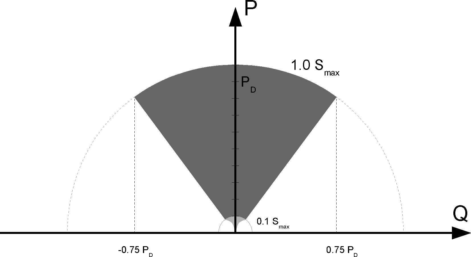 |
Reactive Power capability
If the local grid code is not supported by the inverter/charger an external certified interface device should be used to connect the inverter/charger to the grid.
The inverter/charger can also be used as a bidirectional inverter operating parallel to the grid, integrated into a customer-designed system (PLC or other) that takes care of the control loop and grid measurement.
Special notes regarding NRS-097 (South Africa):
The maximum allowed impedance of the network is 0.28 Ω + j0.18 Ω
The inverter fulfils the unbalance requirement for multiple single-phase units only when a GX device is part of the installation.
Special notes regarding AS 4777.2 (Australia/New Zealand):
IEC62109.1 certification and CEC approval for off-grid use does NOT imply approval for grid-interactive installations. Additional certification to IEC 62109.2 and AS 4777.2.2015 are required before grid-interactive systems can be implemented. Please check the Clean Energy Council website for current approvals.
DRM – Demand Response Mode
When the AS4777.2 grid code has been selected in VEconfigure, DRM 0 functionality is available on port AUX1 (see appendix A)
To enable grid connection, a resistance of between 5kOhm and 16kOhm must be present between the terminals of port AUX1 (marked + and - ). The MultiPlus-II will disconnect from the grid in case of an open circuit or a short circuit between the terminals of port AUX1. The maximum voltage that may be present between the terminals of port AUX1 is 5 V.
Alternatively, if DRM 0 is not required, this functionality can be disabled with VEConfigure.
*This functionality is neither UL1741 certified nor CSA 22.2 No.107.1.