5. Configuration and settings
The solar charger settings can be configured so it can be taylored specifically for the system it is used in.
Caution
Do not change solar charger settings unless you know what they are and what the effect of changing these settings is going to be.
Incorrect settings may cause system problems including damage to batteries. When in doubt, seek advice from an experienced Victron Energy installer, dealer or distributor.
5.1. How to change settings
There are several methods that can be used to change these settings. Some of these allow all settings to be configured, but others might have limitations:
The VictronConnect app - All settings can be changed and the firmware can be updated.
The rotary switch - The charge algorithm for a number of pre-set battery types can be selected.
The MPPT Control display (optional) - Most settings can be changed.
The SmartSolar display (optional) - All settings can be changed
Important
Do not change solar charger settings unless you know what they are and what the effect of changing these settings can be. Incorrect settings may cause system problems including damage to batteries. When in doubt, seek advice from an experienced Victron Energy installer, dealer or distributor.
5.1.1. Settings via the VictronConnect app
The VictronConnect app can be used to change all solar charger settings and can be used to update the firmware.
See the VictronConnect app chapter for an overview of the different ways the VictronConnect app can connect to the solar charger.
This manual only covers the VictronConnect app solar charger-specific items. For more general information on the VictronConnect app, like how to use it or how to connect, see the VictronConnect manual.
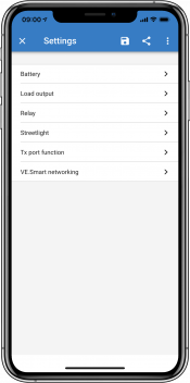 |
To access the solar charger settings, navigate to the settings page. Do this by clicking on the cog icon  at the top right of the home screen.
The settings page provides access to view and/or to change the solar charger settings.
For information about each setting and how to update firmware see the Updating firmware chapter.
5.1.2. Settings via the rotary switch
The rotary switch can be used to select eight pre-programmed battery charge algorithms.
Use a small flathead screwdriver to turn the rotary switch. The arrow indicates which setting number has been selected.
The table below indicates the charge algorithm and charge settings for each rotary switch position.

Rotary switch set to position 2
Notice
Turning the rotary switch will override the charge settings including settings that were made with the VictronConnect app or with the display. Likewise, if charge settings are changed with the VictronConnect app or the display, this will override the rotary switch setting.
Switch position | Suggested battery type | Absorption voltage* (V) | Float voltage* (V) | Equalize** voltage* (V) | Equalize** nominal current percentage | Temperature compensation factor* (mV/°C) |
|---|---|---|---|---|---|---|
* The top value is for 12V systems, the middle for 24V systems and the bottom for 48V systems. ** Equalize is by default disabled. To enable see chapter Battery settings | ||||||
0 | Gel long life (OPzV) Gel Exide A600 (OPzV) Gel MK | 14.1 28.2 56.4 | 13.8 27.6 55.2 | 15.9 31.8 63.6 | 8% | -16 -32 -64 |
1 | Gel Victron deep discharge Gel Exide A200 AGM Victron deep discharge Stationary tubular plate (OPzS) | 14.3 28.6 57.2 | 13.8 27.6 55.2 | 16.1 32.2 64.4 | 8% | -16 -32 -64 |
2 | Default setting Gel Victron deep discharge Gel Exide A200 AGM Victron deep discharge Stationary tubular plate (OPzS) | 14.4 28.8 57.6 | 13.8 27.6 55.2 | 16.2 32.4 64.8 | 8% | -16 -32 -64 |
3 | AGM spiral cell Stationary tubular plate (OPzS) Rolls AGM | 14.7 29.4 58.8 | 13.8 27.6 55.2 | 16.5 33.0 66.0 | 8% | -16 -32 -64 |
4 | PzS tubular plate traction batteries or OPzS batteries | 14.9 29.8 59.6 | 13.8 27.6 55.2 | 16.7 33.4 66.8 | 25% | -16 -32 -64 |
5 | PzS tubular plate traction batteries or OPzS batteries | 15.1 30.2 60.4 | 13.8 27.6 55.2 | 16.9 33.8 67.6 | 25% | -16 -32 -64 |
6 | PzS tubular plate traction batteries or OPzS batteries | 15.3 30.6 61.2 | 13.8 27.6 55.2 | 17.1 34.2 68.4 | 25% | -16 -32 -64 |
7 | Lithium Iron Phosphate (LiFePo4) batteries | 14.2 28.4 56.8 | 13.5 27.0 54 | n/a | n/a | 0 0 0 |
A binary LED code helps determining the position of the rotary switch. After changing the position of the rotary switch, the LEDs will blink during 4 seconds as indicated in below table. Thereafter, normal indication resumes, as described in the LEDs section.
Switch position | Bulk LED | Absorption LED | Float LED | Blinking frequency |
|---|---|---|---|---|
0 | 1 | 1 | 1 | Fast |
1 | 0 | 0 | 1 | Slow |
2 | 0 | 1 | 0 | Slow |
3 | 0 | 1 | 1 | Slow |
4 | 1 | 0 | 0 | Slow |
5 | 1 | 0 | 1 | Slow |
6 | 1 | 1 | 0 | Slow |
7 | 1 | 1 | 1 | Slow |
5.1.3. Settings via the SmartSolar Control display
The optional SmartSolar Control display can be used to configure solar charger settings. For information on how to do this see the SmartSolar Control display manual.
 |
The SmartSolar Control
5.1.4. Settings via MPPT Control display
The optional MPPT Control display can be used to configure solar charger settings, with the exception of advanced settings such as RX and TX port settings. For information on how to do this see the MPPT Control manual.
 |
The MPPT Control
Note
Although the MPPT Control can connect to the solar charger, consider using a SmartSolar control display instead.
5.2. All settings explained
This chapter lists all solar charger settings that are user-configurable and also explains how to update firmware of the solar charger.
Caution
Do not change settings unless you know what they are and what the effect of changing these settings will be. Incorrect settings may cause system problems including damage to batteries. When in doubt, seek advice from an experienced Victron Energy installer, dealer or distributor.
5.2.1. Battery settings
 |
Battery voltage
The battery voltage is automatically detected at the very first power-up of the solar charger and the battery voltage is set accordingly. Further automatic detection is disabled. To make sure that a stable measurement is used, the charger first waits 10 seconds, and thereafter takes an averaged measurement. Note that the solar charger will remain off during this time.
In case the solar charger does not measure a battery voltage, it will default to 12V and store that. This will happen if the solar charger is powered via its PV terminals, while not connected to a battery.
Note that the solar charger will not automatically detect a 36V battery. This will need to be set manually.
After automatic detection has taken place, the battery voltage can be changed and set to 12, 24, 36 or 48V, if so required .
Tip
Tip:
If the firmware of the solar charger needs to be updated, while keeping the automatic voltage detection active, for example before shipping the unit to an end-user, do the following:
Update the firmware.
Once the firmware update is complete, go to the settings page in the VictronConnect app.
On the settings page, click on the three vertical dots in the upper right corner and select "Reset to defaults” from the drop-down menu.
Un-power the solar charger within 10 seconds.
The next time that the unit is powered up, it will perform the initial automatic voltage detection.
Max charge current
This setting sets the maximum battery charge current. It is by default set to the maximum solar charge current.
Use this setting to reduce the charge current, for example, when a smaller battery bank is used that requires a lower charge current.
Charger enabled
This setting enables or disables the battery charger. It is by default set to "enabled".
This setting can be used when work needs to be carried out on the installation. When this setting is disabled, the batteries will not be charged.
Battery preset
This setting sets the battery charge algorithm. It is by default set to "rotary switch".
A selection can be made between:
The rotary switch position.
Pre-defined factory battery presets.
User-defined battery presets.
Create, modify or delete a user-defined preset.
This setting uses factory pre-defined presets for a large variety of battery types. These pre-defined charge algorithms are suitable for almost all installations.
It is possible to also create user-defined battery presets. The chapter Customize battery charge algorithm explains how to do this. These user-defined presets are stored in the VictronConnect app library. This is helpful in case multiple solar chargers need to be configured, eliminating the need to define the entire charge algorithm each time a new solar charger is configured.
Expert mode
This setting enables or disables expert mode. It is by default set to "disabled".
Caution
The default charge algorithms work well for almost all installations. Only enable expert settings if your equipment has special requirements.
When this setting is enabled the following parameters can be configured:
Charger voltages: bulk, absorption and float.
Bulk: re-bulk voltage offset.
Absorption: duration, time and tail current.
Equalization: current, interval, stop mode and duration.
Temperature voltage compensation.
Low temperature cut off.
For the meaning of these parameters see chapter Battery charge algorithm settings.
Equalization
Caution
Equalization can cause damage to the battery if the battery is not suitable for an equalization charge. Always check with the battery manufacturer prior to enabling equalization.
This setting can be used to disable or enable automatic equalization. When enabled, the number of days can be selected when equalization should repeat.
A manual equalization can be initiated by pressing the "START NOW" button. Use the manual equalize option only during absorption and float charge stages, and when there is sufficient sunlight. The current and voltage limits are identical to the automatic equalize function. The manual equalization stage lasts 1 hour and can be stopped at any time by the Stop Equalize.
Notice
The equalization setting might not be active, this can be the case if the battery preset does not support an equalization charge which is the case with lithium batteries.
Customize battery charge algorithm
This chapter explains how to modify a battery charge algorithm or to create, modify and delete user defined battery presets. See the Battery charge algorithm settings chapter for the meaning of all charge algorithm parameters.
 |
Caution
Only experienced users should configure or edit user defined battery charge algorithms. A wrongly defined battery charge algorithm can lead to battery damage or create unsafe situations.
To Modify a basic battery charge algorithm:
Select a preset battery type that is the best match to your battery type.
Change one of the basic charge parameters that are listed on the settings screen.
Configure the required parameters.
The battery preset is now set to "user defined".
To Modify an expert battery charge algorithm
Enable "Expert" mode.
The basic and additional charge parameters are now listed on the screen.
Configure the required parameters.
The battery preset is now set to "user defined".
To create and save a custom battery type:
Select a preset battery type that is the best match to your battery type.
Change the charge parameters so they match your battery. This can be done either in normal mode or in expert mode.
The battery preset is now set to "user defined".
Select in the "Battery preset" menu "Create preset".
Give the preset battery a name.
To load a custom battery type:
Select in the "Battery preset" menu "Select preset".
The menu lists all factory preset and custom battery types that were previously added (if any).
Select the battery type of your choice.
To modify (or delete) a custom battery type:
Select in the "Battery preset" menu "Edit presets"
Navigate to the battery you want to modify. It is not possible to modify a factory preset, only custom types can be modified (or deleted).
Modify the charge parameters.
To save the settings press the "SAVE CHANGES" button at the bottom of the page.
To delete the battery, press the "REMOVE PRESET" button.
Battery charge algorithm settings
This chapter explains all parameters that are used in "Expert" mode and the settings that are used when programming a custom battery type via the battery preset menu.
 |
Absorption voltage
This setting sets the absorption voltage.
Adaptive absorption time
This setting enables or disables the adaptive absorption time.
When disabled: The length of the absorption stage is the same each day, the length is determined by the "Maximum absorption time" setting, provided there is enough solar power.
Be aware that this option can potentially result in overcharging your batteries, especially for lead batteries and if only shallow daily discharges take place. Check with the battery manufacturer for the recommended maximum absorption time.
The only condition that can end the absorption time before the maximum time has been reached, is the "tail current" setting. If the absorption time always needs to be the same length, then disable the "Tail current" setting. See more information on the tail current setting further down in this chapter.
When enabled: The length of the absorption stage is different each day, it adapts itself to the state of charge of the battery in the morning at the beginning of the charge cycle.
The maximum "adaptive" absorption time for the day is determined by the battery voltage as measured just before the solar charger begins operation each morning.
Multiplier
x 1
x 2/3
x 1/3
x 1/6
Adaptive absorption time *
6:00 hours
4:00 hours
2:00 hours
1:00 hour
12V system
Vbatt < 11.9V
11.9V < Vbatt < 12.2V
12.2V < Vbatt < 12.6V
Vbatt > 12.6V
24V system
Vbatt < 23.8
23.8 < Vbatt < 24.2V
24.2V < Vbatt < 25.2V
Vbatt > 25.2V
48V system
Vbatt < 47.6
47.6V < Vbatt < 48.8V
48.8V < Vbatt < 50.4V
Vbatt > 50.4
*) The adaptive absorption time is calculated by the multiplier times the "Maximum absorption time" setting. The adaptive absorption times in this table are based on the 6 hour default "Maximum absorption time" setting.
Maximum absorption time
This setting sets the absorption time limit. This setting is only available when programming a custom charge profile.
Enter the maximum time in hours and minutes (hh:mm) the solar charger is allowed to spend in the absorption stage. The maximum time that can be set is 12 hours and 59 minutes.
Float voltage
This setting sets the float voltage.
Re-bulk voltage offset
This setting sets the re-bulk voltage offset. This offset voltage is used to determine when a charge stage stops and the bulk stage starts again, i.e. the charge cycle resets and starts at the first charge stage again.
The re-bulk voltage is calculated by adding the re-bulk voltage offset to the lowest voltage setting (normally this is the float stage).
An example: If the re-bulk offset is set at 0.1V and the float voltage at 13.8V, the charge cycle will restart once the battery voltage drops below 13.7V (13.8 minus 0.1) for one minute.
Equalization voltage
This setting set the equalization voltage.
Equalization current percentage
This setting sets the percentage of the "maximum charge current" setting that will be used to calculate the equalization charge current.
For example: If the "maximum charge current" setting is set at 10A and the "Equalization current percentage" setting is set to 10%, the Equalization current will be 1A (10% of 10A).
Automatic equalization
This setting sets the repeat interval when the equalization stage should take place. This can be set between 1 and 250 days. Setting to 1 means a daily equalization, 2 means every other day and so on.
An equalization stage is typically used to balance the cells and also to prevent stratification of the electrolyte in flooded lead-acid batteries. If equalization is needed or not depends on the type of battery if (automatic) equalization is needed and under what conditions. Check with the battery supplier to find out if equalization is needed for the battery.
During the equalization stage, the charge voltage increases up to the set "Equalization voltage". This is maintained as long as the charge current stays below the "equalization current percentage" setting of the "Maximum current" setting.
Duration of the Automatic equalization cycle:
For all VRLA battery presets and for some flooded battery presets, the automatic equalization stage ends when the voltage limit (maxV) has been reached.
For the lithium battery preset, equalization is not available.
When an automatic equalization stage has not been completed within one day, it will not resume the next day. The next equalization surge will take place according to the interval as set in the "Auto Equalization" setting.
Equalisation stop mode
This setting determines when the equalisation stage should end:
Automatic: Equalization stops if the battery voltage has reached the equalisation voltage.
Fixed time: Equalization stops when the time has reached the time as set in the "Maximum equalization duration" setting.
Maximum equalization duration
This setting sets the maximum time that the equalization stage will last.
Manual equalization
Use this to perform a "once-off" equalization. Once the "start now" button is pressed, a one-hour equalization cycle will be performed, alternatively, the equalization stage can be stopped manually.
Tail current
This setting sets the current threshold to end the absorption stage before the maximum absorption time has been reached. If the charge current drops below the set tail current, for one minute, the absorption stage will end and the float stage will start. This setting can be disabled by setting it to zero.
Temperature compensation
This setting sets the temperature compensation coefficient that is needed for temperature compensated charging.
Many battery types require a lower charge voltage in warm operating conditions and a higher charge voltage in cold operating conditions. The configured coefficient is in mV per degree Celsius for the whole battery bank, not per cell. The base temperature for the compensation is 25°C (77°F).
The chart below indicates the absorption and float charge voltage behaviour at different temperatures. The graph displays the temperature compensation for a 12V system and uses a -16mV/°C temperature compensation coefficient. For a 48V system multiply by 4.
 |
Temperature compensated charge graph
By default, the solar charger uses its internal temperature for battery temperature compensated charging. An internal temperature reading is taken in the morning and then again when the e solar charger has been idle for at least one hour, for example when the charger is not actively charging a battery or supplying a load.
When the solar charger is part of VE.Smart Networking and receives a battery temperature reading from a Battery Sense or a battery monitor with a temperature sensor, the actual battery temperature will be used for temperature compensated charging throughout the day.
Low temperature cut-off
This setting is used to prevent damage to a lithium battery by disabling charging at low temperatures.
Warning
The "Low temperature cut-off" feature is only active when the solar charger is part of a VE.Smart network and is receiving a battery temperature reading from a Battery Sense or a battery monitor with temperature sensor.
The "low temperature cut-off" setting is by default disabled. When enabled, a low cut off temperature can be set. The default temperature is 5°C, this is a suitable temperature setting for lithium iron phosphate (LFP) batteries. However, always check with the lithium battery supplier to find out what this temperature should be set at.
The "low temperature cut-off" mechanism will stop battery charging when the battery temperature has dropped below the low temperature cut-off setting. Battery charging will resume once the battery temperature has risen 0.5°C above the low temperature cut-off setting.
Note that setting "low temperature cut-off" is not needed for Victron Lithium Smart batteries or for Victron Super Pack batteries with serial number HQ2040 and above. This setting is only needed for lithim batteries that are unable to block charging when the temperature drops too low.
5.2.2. Load output settings
The load output settings used to control the VE.Direct TX port or the relay, enabling it to operate a BatteryProtect, a relay or another load-shedding device. For more information, see the chapter TX port settings.
 |
BatteryLife (default setting):
This algorithm is self-adapting and aims to maximise the battery's lifespan. For a detailed explanation of its functionality, please refer to the BatteryLife chapter for a description of its functionality.
Conventional algorithm 1:
12V system: OFF when Vbatt < 11.1V, ON when Vbatt > 13.1V.
24V system: OFF when Vbatt < 22.2V, ON when Vbatt > 26.2V.
48V system: OFF when Vbatt < 44.4V, ON when Vbatt > 52.4V.
Conventional algorithm 2:
12V system: OFF when Vbatt < 11.8V, ON when Vbatt > 14.0V.
24V system: OFF when Vbatt < 23.6V, ON when Vbatt > 28.0V.
48V system: OFF when Vbatt < 47.4V, ON when Vbatt > 56.0V.
Always off:
The load output is always OFF.
Always on:
The load output is always ON.
User defined algorithm 1:
OFF when Vbatt < Vlow.
ON when Vbatt > Vhigh.
User defined algorithm 2:
OFF when Vbatt < Vlow or Vbatt > Vhigh.
ON when Vbatt is between Vlow and Vhigh.
The "always off" and the "always on" modes will respond immediately. The other modes have a 2-minute delay before the load output changes. This is so that the solar charger does not respond too quickly when, for example, an inrush current briefly lowers the battery voltage below the threshold.
The load output settings also control the streetlight algorithm. Both work together to protect the battery from being too deeply drained. The streetlight settings are overridden should the battery voltage falls below the load disconnect voltage. When the battery voltage increases to the load reconnect voltage, the streetlight function will resume.
5.2.3. Programmable relay settings
The programmable relay can be configured to a variety of relay modes. Each mode will cause the relay to switch under different conditions. Some of these conditions are pre-determined and some are customizable. In addition to the "relay mode" a relay minimum closed time can be set.
 |
The programmable relay offers three connections:
NO (Normally Open)
C (Common)
NC (Normally Closed)
Relay State | Connection between |
|---|---|
Switched ON | C and NO |
Switched OFF | C and NC |
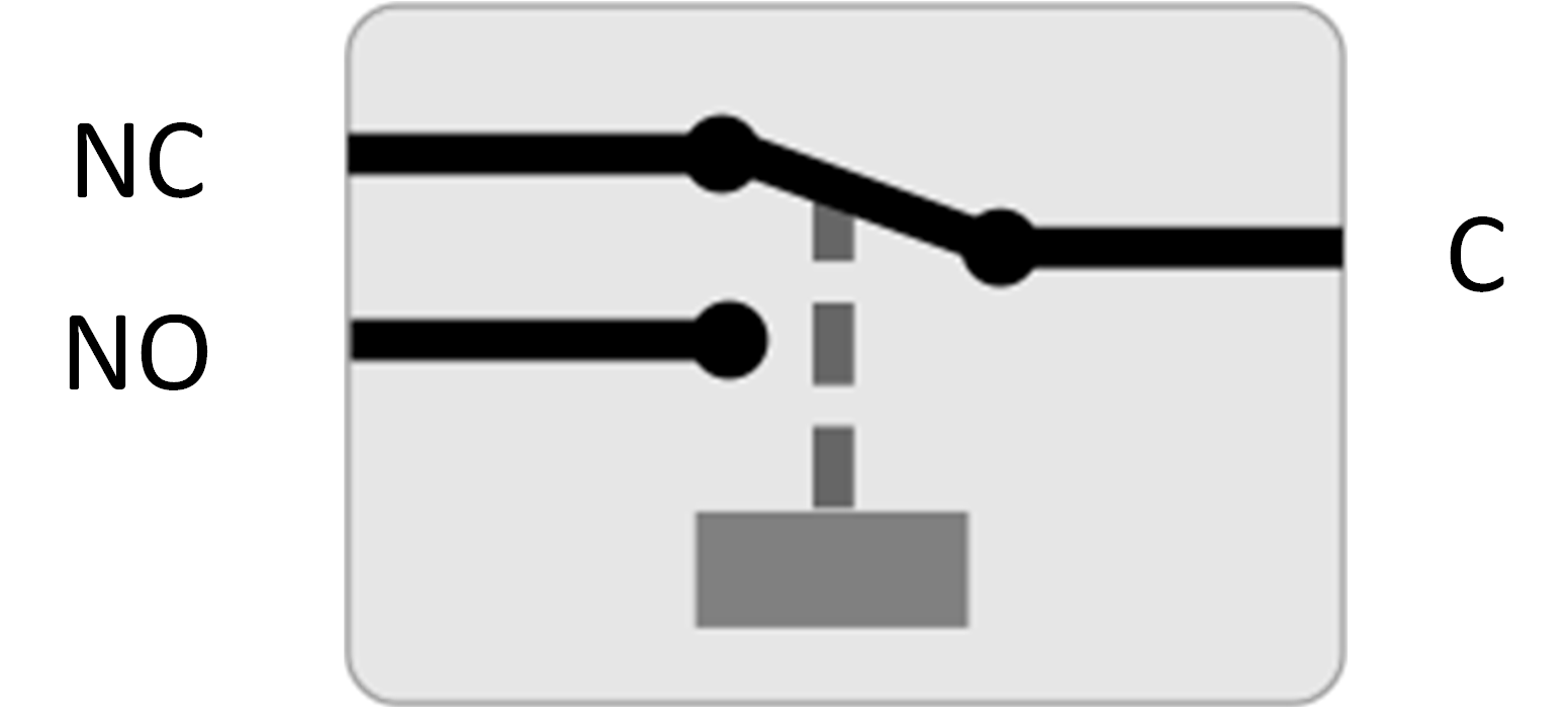 |
Internal operation of the programmable relay
Relay mode | Description and notes |
|---|---|
Relay always off | This option switches the relay OFF. It will disable the other relay options. Use this option if you do not plan to use the relay function. |
Panel voltage high | This option switches the relay ON when the panel voltage becomes too high. Panel voltage High settings Panel high voltage. (User-defined Voltage) Clear panel high voltage. (User-defined Voltage) This option switches the relay ON when the panel voltage rises above the chosen “Panel high voltage” setting, and switches the relay OFF when the panel voltage falls below the chosen “Clear panel high voltage” setting. Ensure, of course, that the “Panel high voltage” setting is greater than the “Clear panel high voltage” setting. These settings must never exceed the maximum voltage-rating allowed by your MPPT charger. |
High temperature (Dimming) | This option switches the relay ON when the charger output current is reduced due to high temperatures. Use this option to for example switch an external fan. |
Battery voltage Low | This option switches the relay in ON when the battery voltage falls too low, This is the default setting when the relay function is active. Battery voltage Low settings Battery low-voltage relay. (The default setting for this is 10.00V) (12V battery assumed) Clear battery low-voltage relay. (The default setting for this is 10.50V) These settings, which can be user-defined, will cause the relay to switch ON when the battery voltage falls below the chosen “Battery low-voltage” setting; and will cause the relay to switch OFF when the battery voltage once again rises above the “Clear battery low-voltage” setting. Ensure, of course, that the “Battery low-voltage relay” setting is lower than the “Clear battery low-voltage relay” setting. An application for this feature, for example, is to automatically disconnect a load in order to prevent a battery from becoming too deeply discharged. |
Equalization active | This option switches the relay ON when the manual equalization mode is active. |
Error state | This option switches the relay ON when there is an error. |
Defrost option (Temp < -20 °C) | This option switches the relay ON when the Charger temperature falls below -20 degrees Centigrade. |
Battery voltage high | This option switches the relay ON when the battery voltage is too high. Battery voltage High settings Battery high-voltage relay. (The default setting for this is 16.50V) (12V battery assumed) Clear battery high-voltage relay. (The default setting for this is 16.00V) These settings, which can be user-defined, will cause the relay to switch ON when the battery voltage rises above the “Battery high-voltage relay” setting; and will cause the relay to switch OFF when the battery voltage drops below the “Clear battery high-voltage relay” setting. Ensure, of course, that the “Battery high-voltage relay” setting is greater than the “Clear battery high-voltage relay” setting. An application for this feature, for example, is to disconnect a load in order to protect it from an over-voltage. |
Float or Storage state | This option switches the relay ON when the charger is in the float state. |
Day detection | (Panels irradiated). This option switches the relay ON whilst the solar panels are providing energy (Day/Night detection). |
Notice
The switching conditions must be present for at least 10 seconds before the relay will change position.
Setting | Description |
|---|---|
Minimum closed time | Set by default setting to 0 minutes and is customizable. The minimum-time can be set for the ON condition to prevail once the relay has been switched ON. An example where a minimum closed time is usefull, is to set a minimum generator run-time. |
5.2.4. Streetlight settings
The streetlight function enables the solar charger to automatically control night lighting. It will automatically determine when the light should be on or off and can control the light intensity.
When the streetlight function is enabled a timer program can be created whereby Sunset, Sunrise as well as Midnight can be used as anchor points for the timer program. These anchor points will automatically adjust depending on length of the night as this changes with the seasons.
 |
Streetlight control
The solar charger controls the streetlight:
Via the TX port together with a VE.Direct TX digital output cable. Also see the TX port settings chapter for more details.
Via the programmable relay. Also see the Programmable relay settings chapter for details.
Notice
The streetlight algorithm is always applied in conjunction with the settings as configured in the Load output menu:
If the streetlight is disabled, then the (virtual) load output is controlled only by the configuration as made in the load output menu.
If streetlight is enabled, then it's an AND function: the load output will be on when both the conditions made in the Load output menu are satisfied as well as the streetlight settings. Otherwise, it's off.
Make sure that load output setting is set to "Always on" or to "BatteryLife". Do not set it to "Always off" as this will result in the light being always off.
For more configurable voltage levels to force the light off, the other load output options can also be used.
Setting the Sunset action
At sunset you can choose any of the following actions:
Keep the lights off
Switch on for a fixed time:
This option will turn the light on at sunset, and then off again after a configurable interval. When the dimming feature is enabled1 (1), two dim-levels can be entered: one for the “on” period; and a second for the “off” period. A typical use case for these options is to get a strong light during high traffic hours (right after sunset), and lower intensity during the low hours, to save the battery. Set the second dim level to 0% to switch the light completely off during that second section.
Switch on till midnight:
This option turns the light on at sunset, and then off again at midnight. When the dimming feature is enabled1, two dim-levels can be entered: one for the “on” period (up to midnight) and a second dim-level for the “off” period after midnight. Set the second dim level to 0% to switch the light completely off during that second section.
Switch on till sunrise:
This options turns the light on at sunset, and then off again at sunrise. When this option is selected; there is no need to also select an action at sunrise, so the sunrise control option is not needed. When the dimming feature is enabled1, only one dim level can be configured, the dim level at sunset.
1) The dimming feature requires the TX Port function to be configured to one of the "Light dimming" settings. This so the TX port outputs a PWM signal that can be used to dim the light. If the TX port function has not been set to one of the "Light dimming" settings, the dimming options will not appear in the sunset settings menu. Also see the TX port settings chapter.
Setting the Sunrise action
At sunrise you can choose to:
Switch off:
Turns the light off at sunrise.
Switch on before sunrise:
This option switches the light on at a configurable time interval before sunrise, and then switches the light off at sunrise.
In case the dimming feature is enabled1 an interval of more intense light can be configured during early morning rush hour. Together with the Sunset action, you can now configure three dim levels: one for the sunset rush hours, one during the low traffic hours, and the third for the early morning rush hours.
Midnight
The charger has no real time clock, and therefore does not know when it is 12 o'clock at night. All references to midnight refer to what we call solar midnight, this is the mid-point between sunset and sunrise.
Midnight and Sunrise synchronisation
The solar charger needs to have its internal clock synchronised with the solar cycle so it can set the solar midnight and sunrise anchor points in the timer program.
After the streetlight settings have been programmed and the solar charger is powered up, the solar charger will start unsynchronised. It will first assume that midnight is 6 hours after sunset, and that the full night last for 12 hours.
Once in operation, the solar charger will check the time between each detected sunrise. After three full day/night cycles, where the detected time is approximately 24 hours (one hour of deviation is allowed), it will start using its internal clock, instead of the fixed 6 and 12 hour timing.
Notice
A loss of power (no battery power together with no PV power) will cause the solar charger to loose its synchronisation. It will take 5 days before it is re-synchronised. Note that the streetlight configuration settings and all other settings will never be lost, they are stored in a non-volatile memory.
Sunset and sunrise detection
The sunset and sunrise detection voltage settings can be used to adjust the detection to match the panel configuration. The sunrise detection voltage must be 0.5V higher than the sunset detection level. The lowest detectable voltage is 11.4V. Set this option to 0 to use the built-in defaults, which are:
Sunset = Vpanel < 11.4V.
Sunrise = Vpanel > 11.9V.
The default setting is 0, which uses built-in default voltages.
Use the "Delay" periods to avoid the system making an accidental switch when clouds pass over the panels. The valid range is between 0 and 60 minutes. The "Delays" are disabled by default (0).
Gradual dimming speed
The gradual dimming option can be used to slow down the response of the timer program. This is useful when multiple streetlights are used in a row. This helps to mask the fact that each timer uses its own detection and will have a transition moment which will vary from unit to unit.
The dimming settings can be adjusted. You can input the number of seconds required to achieve each percentage-point of change (x seconds/per 1% of dimming). A number from 0 to 100 can be entered. Two examples:
0 = immediate response (gradual dimming disabled):
A setting of 0 will achieve an immediate response, this effective means that the gradual dimming option is disabled.
9 = dim from 0 to 100% in 15 minutes:
Setting the dimming speed to 9, for example, slows down the dimming speed to 15 minutes (9 seconds for each percentage point of dimming x 100 percentage points = 900 seconds = 15 minutes.
Notice
Make sure that the TX port function is set to "Light dimming" mode (as described in point 1 at the beginning of this chapter) and connect a VE.Direct TX digital output cable to the PWM dim input of your LED driver.
Mid-point shift
The time of midnight is estimated based on solar activity, and depends on your geographical location. Daylight saving times can cause a further deviation between the "solar" and the "clock" midnight. The Mid-point shift function will compensate for these differences. Use 0 to disable the shift (default).
Notice
The Mid-point shift setting is only relevant when your streetlight setting program uses "Midnight" as a switching moment.
Calculation Example:
For calculation we use a day of 1440 minutes, where Sunset is at 19:00 (1140 minutes) and Sunrise is at 6:25 (385 minutes):
The night duration in minutes is: 1440m(min/day) -1140m(time to sunset) + 385m(time to sunrise) = 685m.
The degree of shift = time of sunset(minutes) + half the duration of night(minutes) - length of day(minutes) = 1140m + 342m - 1440m = 42 minutes.
Example configuration
 |
The selections which have been made on above screen image results in this program:
At sunset - the light will be switched on for a fixed time.
Dim level at sunset - at Full brightness (100%).
Keep lights on during - the duration has been set to 1h 0m.
Dim level at end - at the end of one hour the brilliance will be reduced to half (50%).
Also:
At sunrise - the lighting will be adjusted before sunrise.
Time before sunrise - at 1h 0m before sunrise, the following adjustment will be made:
Dim level - full brilliance will be restored (100%).
5.2.5. TX port settings
The VE.Direct-TX port can be used to send a signal to an external device. For example, to send a PWM signal to dim a streetlight.
To use the TX port, a VE.Direct TX digital output cable is needed.
 |
The functionality of the TX port can be set at:
Normal communication:
This is the default setting. Use this function when connecting to a GX device, a VE.Direct Bluetooth Smart dongle, or any other device that needs to communicate with the solar charger via the VE.Direct port.
Pulse every 0.01 kWh:
Use this function in combination with an energy meter.
The TX port will emit a pulse each time an additional 0.01kWh of energy has been harvested. The TX port is normally high and will be driven low for approximately 250ms for every 0.01kWh harvested.
Light dimming (PWM normal):
Use this function in combination with the "Streetlight" setting.
The TX port PWM* signal will be at 100% duty cycle when full light intensity is required.
Light dimming (PWM inverted):
Use this function in combination with the "Streetlight" setting.
The TX port PWM* signal will be at 0% duty cycle when full light intensity is required.
Virtual load output:
Use this function to create a virtual load output if the solar charger does not have a physical load output.
The TX port will switch using the same conditions as set in the load output settings.
Connect the VE.Direct TX digital output cable to a BatteryProtect module, a relay or directly to the remote on/off connector of the load**.
*) The PWM signal is 5V, 160Hz.
**) The TX port is a logic 5V signal. It can drive a maximum of a 22kOhm impedance load, where the output voltage is dropped to 3.3V. Make sure that the connected load is within this specification.
Note that these functionalities (other than the first functionality) do not disable the ability of the unit to communicate. What happens is that the unit will automatically detect incoming data, and while data is being received, it will resume normal communication. Once the data reception has been completed, it will automatically return to its configured TX function.
For more in-depth "developer style" information on the VE.Direct port see the Data communication with Victron Energy products document.
5.2.6. RX port settings
The VE.Direct-RX port can be used to receive a signal from an external device. For example to switch the solar charger on (or off) from a signal sent by a battery management system (BMS).
To use the RX port for remote on/off control a VE.Direct non inverting remote on/off cable is needed.
 |
The functionality of the RX port can be set at:
Remote on/off:
This is the default setting. This functionality will switch the solar charger on or off via the RX pin.
- RX pin to GND will switch the solar charger off.
- RX pin floating or to battery positive will switch the solar charger on.
Load output on/off inverted:
This setting reverses the load output on/off control:
- RX pin 0V will switch load output on.
- RX pin +5V will switch load output off.
Load output on/off normal:
This setting allows load output on/off control:
- RX pin 0V will switch the load output off.
- RX pin +5V will switch load output on.
For more in depth "developer style" information on the VE.Direct port see the Data communication with Victron Energy products Whitepaper.
5.3. Updating firmware
The firmware can be checked and updated with the VictronConnect app.
The VictronConnect app might ask on the first connection to update the firmware. If this is the case, let it perform a firmware update.
If it did not automatically update, check if the firmware is already up to date using the following procedure:
Connect to the solar charger.
Click on the settings symbol
.Click the options symbol
 .
.Go to product info.
Check if you are running the latest firmware and look for the text: “This is the latest version”.
If the solar charger does not have the most up-to-date firmware, perform a firmware update.
5.4. VE.Smart Networking
 |
VE.Smart Networking allows a variety of products connected to the same network to share data via Bluetooth and is specially designed for smaller systems that do not have a GX device installed.
When this product is part of a VE.Smart Network, it can receive data or communicate with the following devices:
All SmartSolar solar chargers.
All BlueSolar solar chargers connected to a VE.Direct Bluetooth Smart dongle.
The Smart Battery Sense.
A BMV or SmartShunt battery monitor equipped with Bluetooth (or VE.Direct Bluetooth Smart dongle) and an optional BMV temperature sensor.
Certain Smart AC chargers.
The SUN inverter.
For the product compatibility list see the VE.Smart manual located on the VictronConnect app product page.
VE.Smart Networking can be used for:
Temperature sensing - the measured battery temperature is used by the chargers in the network for temperature compensated charging and in case of lithium battery for the low temperature cut off.
Battery voltage sensing - the measured battery voltage is used by the chargers in the network to to compensate the charge voltage should there be a voltage drop over the battery cables.
Current sensing - The measured battery current is used by the charger so it knows the exact tail current at which the absorption stage should end and the float (or equalisation) stage should start. To measure the charge current all charge currents from all chargers are combined, or if a battery monitor is part of the network the actual battery current will be used.
Synchronised charging - All chargers in the network will act as they were one large charger. One of the chargers in the network will assume a master role and the master will dictate the charge algorithm the other chargers will be using. All chargers will follow the same charge algorithm and charge stages. The master is selected randomly (not user settable) so it is important that all chargers use the same charge settings. During synchronised charging each charger will charge up to its own maximum charge current setting (it is not possible to set a maximum current for the whole network). For more information see the VE.Smart manual located on the VictronConnect app product page.
This video introduces the Smart Battery Sense and some features of VE.Smart Networking:
5.4.1. VE.Smart Networking setup
VE.Smart Networking design notes:
There can only be one product in the network that transmits battery voltage and/or battery temperature. It is not possible to use a battery monitor together with a Smart Battery Sense, or multiple of these devices.
For the network to be operational all networked devices must be within Bluetooth transmission distance of each other.
A maximum of 10 devices can be joined into a VE.Smart Network.
Some older devices might not support VE.Smart Networking. for more information see the Limitations chapter in the VE.Smart Networking manual.
Setting up the network
When setting up the network, first set up the Smart Battery Sense or battery monitor, and then add one or more solar chargers or AC chargers to the network.
All solar chargers and AC chargers need to have the same charge settings. The easiest way to do this is to use a preset battery type or a saved used defined battery type. A warning #66 message will be shown if there is a difference between the devices charge settings.
To set up a new network:
Open the VictronConnect app.
Select one of the devices that needs to become part of the new VE.Smart network.
Navigate to the settings page by clicking the gear
symbol.click on "VE.Smart networking".
Click on "create network".
Enter a name for the new network.
Click "save".
Wait for confirmation that the network has been set up and click "OK".
If more devices need to be added to this network go to next paragraph and join multiple devices to the network.
To join another device to an existing network:
Open the VictronConnect app. Select a device that needs to become part of a VE.Direct network.
Navigate to the settings page by clicking the gear
symbol.Click on "VE.Smart Networking".
Click on "join existing".
Select the network the device needs to be joined to.
Wait for confirmation that the network has been set up and click "OK".
Repeat above steps if more devices need to be added to the network.
To leave a network:
Open the VictronConnect app.
Select a device that needs to be removed from the VE.Direct network.
Navigate to the settings page by clicking the gear
symbol.Click on "VE.Smart Networking".
Click on "leave network".
Check the network
Once the network has been set up all devices communicate with each other. The active LED on each connected device will now blink every 4 seconds. This is an indication that the device is actively communicating with the network.
To check if an individual device is communicating with the network, click on the VE.Smart symbol  in the main screen next to the solar dail. A pop-up window will open showing the connection status and the shared parameters.
 |
VE.Smart Networking pop-up
To check if all devices are actively communicating with the same VE.Smart Networking, navigate to the settings page of one of the networked devices and click on "VE.Smart Networking". A screen will be shown containing which device parameters of this device are shared and all the other devices that are connected to the same network are shown.
 |
Example of a VE.Smart Network
More information
For more information see the VE.Smart Networking manual.