7. Appendix
In this section:
7.1. Connection overview
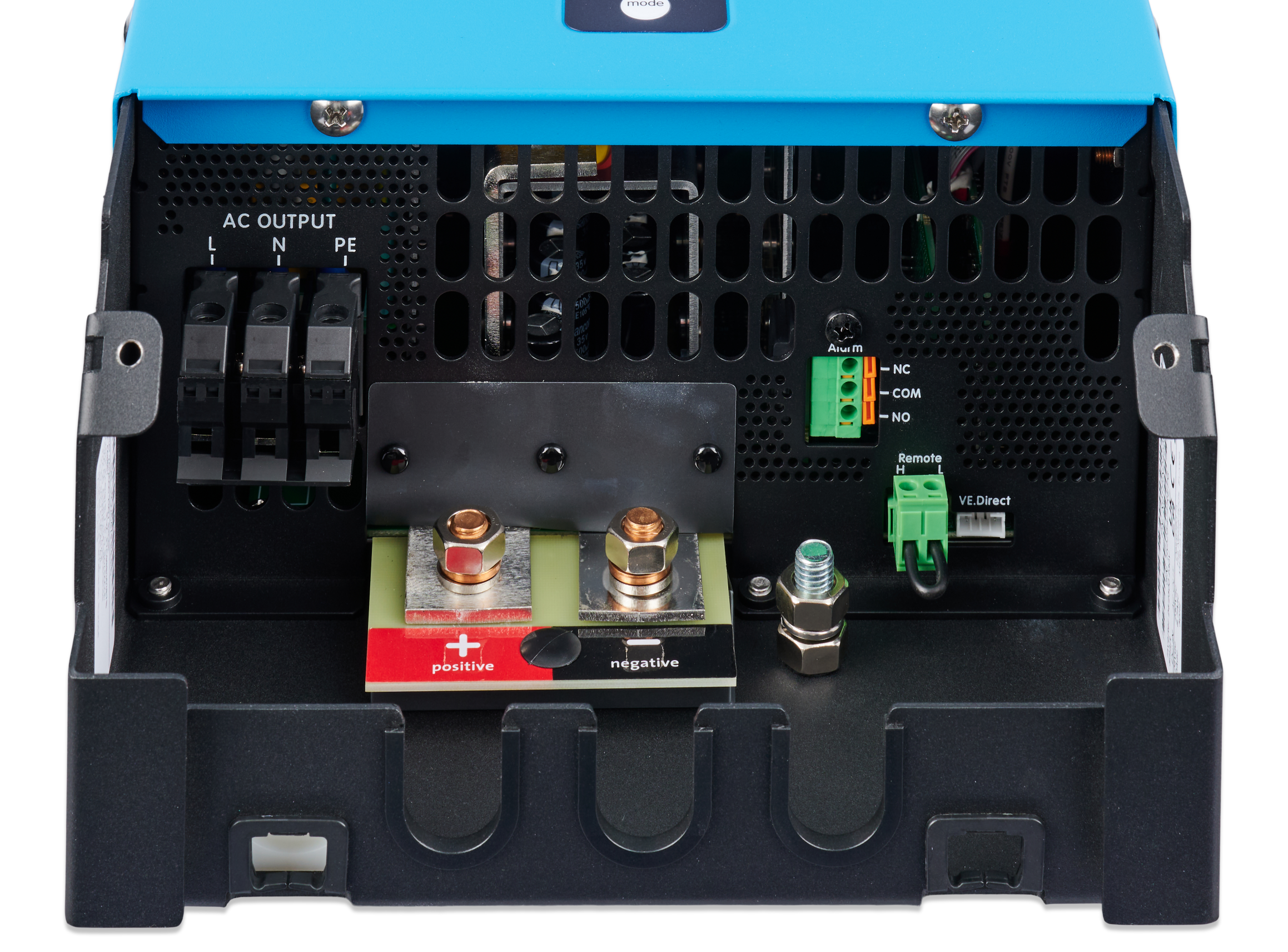 |
Connections 2k5 model
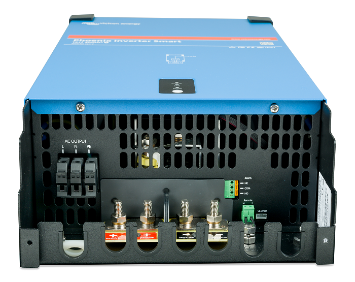 |
Connections 4k model
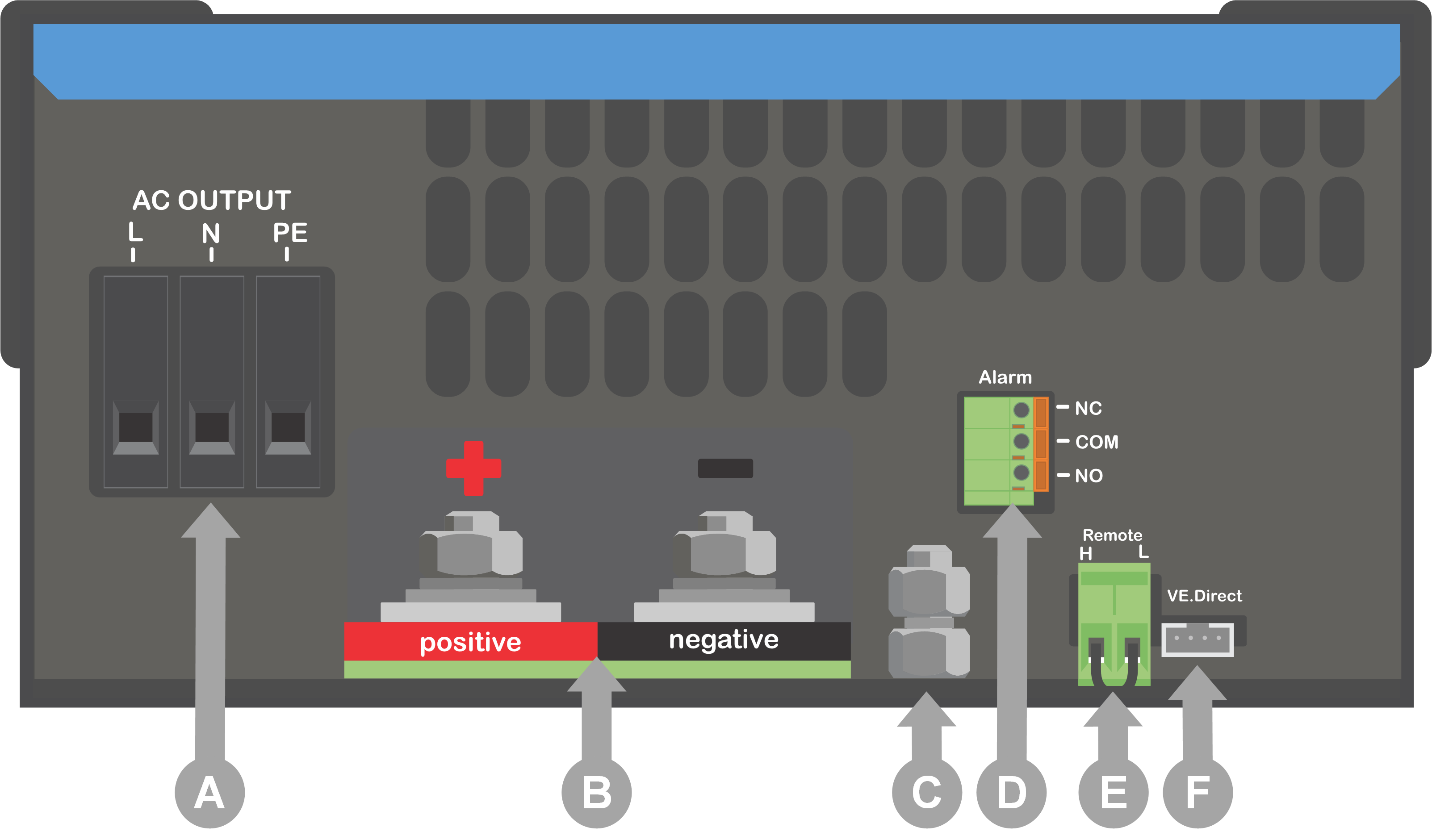 |
# | Connector | Terminal names |
|---|---|---|
A | AC output | L (phase), N (neutral), PE (earth) |
B | Battery | + (positve), - (negative) |
C | GND | Chassis grounding lug |
D | Alarm (programmable relay) | NO, COM, NC |
E | Remote | H, L |
F | VE.Direct | VE.Direct |
7.2. Installation information floating ground
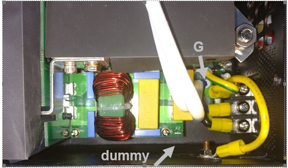
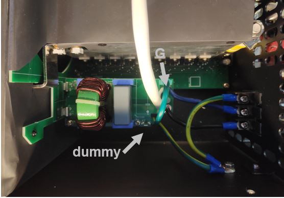
Ground wire “G“ connects the output neutral to ground. It must be re-positioned to a "dummy" terminal if a floating output is required.
When a floating output is obtained, the current reading at no load can show an offset of around 100 - 50mA. Also beware that a GFCI (or RCCB) will not function properly.
The image on the right applies to the 2k5 model. |
|
The image on the right applies to the 4k model. |
|
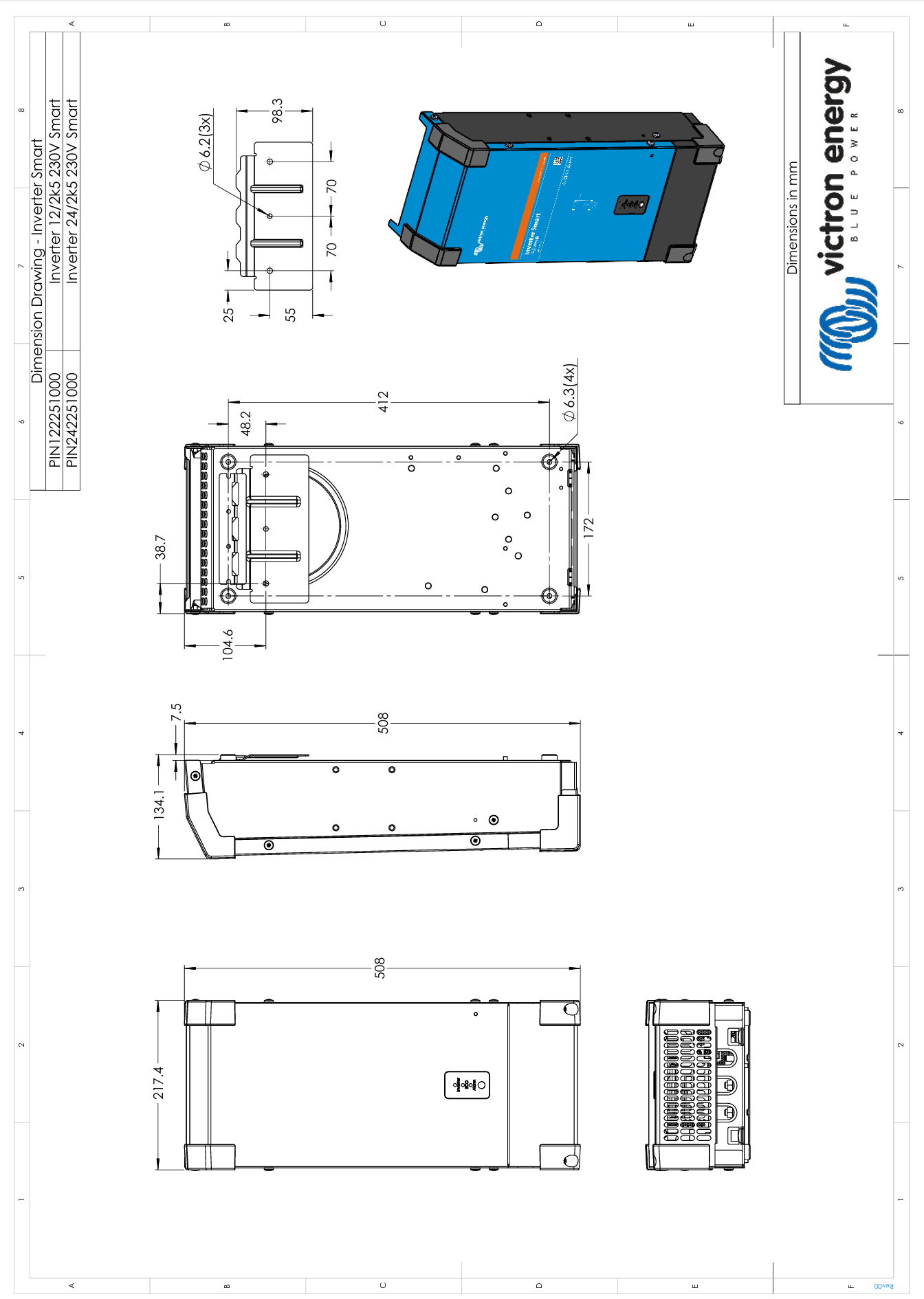
7.3. Dimensions - 2k5 model
7.4. Dimensions - 4k model (12V)
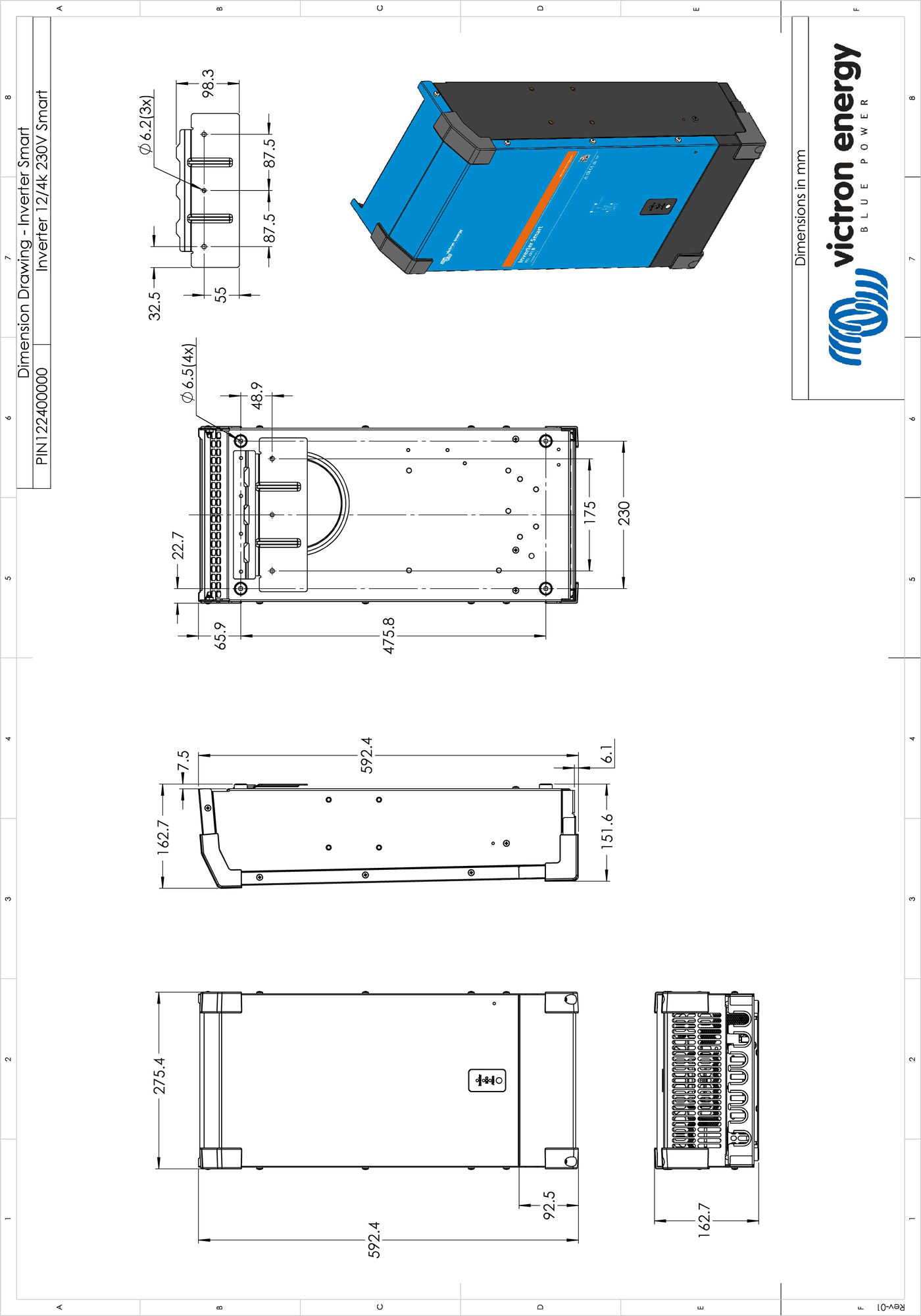
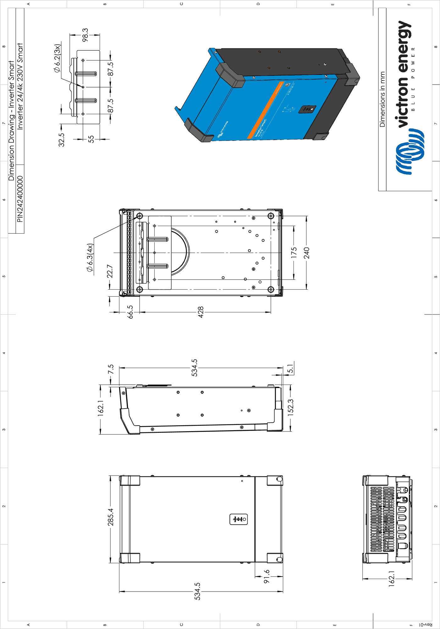
7.5. Dimensions - 4k model (24V)