8. Advanced Configuration
8.1. Advanced settings
In specific use cases where the integrated charge modes are not suitable/ideal for the battery type being charged, or the battery manufacturer recommends specific charge parameters and fine tuning is desired, advanced configuration is possible using a Bluetooth enabled device (mobile phone or tablet) with the VictronConnect app.
For most common battery types, advanced configuration is not required or recommended; the integrated charge modes and adaptive charge logic are typically suitable and perform very well.
The advanced settings page enables specific configuration of charge parameters and user defined settings to be saved and easily selected.
To access the advanced settings:
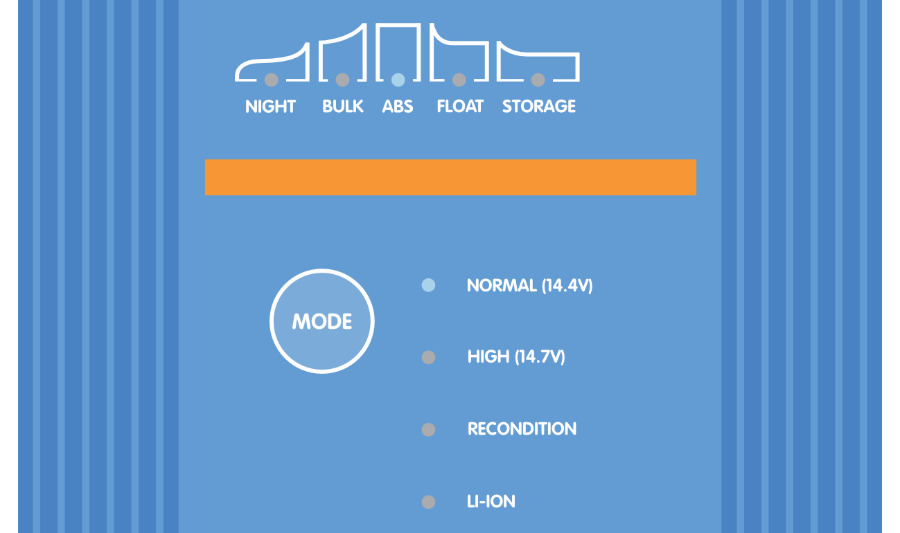
Connect the Blue Smart IP22 Charger AC power cable to a mains power outlet; after a short delay the LEDs indicating the current charge mode and charge state will illuminate.
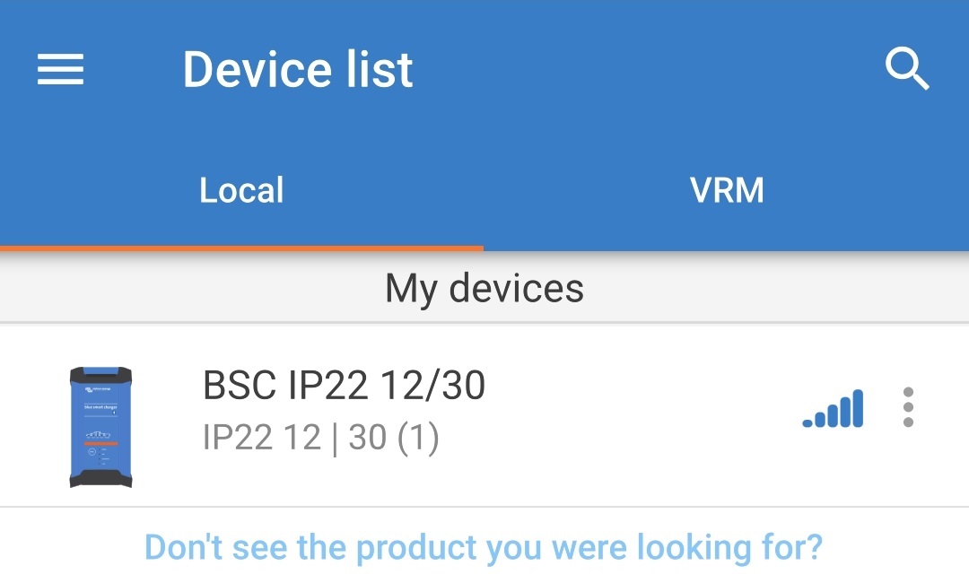
Using a Bluetooth enabled device (mobile phone or tablet), open the VictronConnect app and locate the Blue Smart IP22 Charger in the Device list Local page, then connect to the device (the default PIN code is stated on a label located on the back of the charger, or try 000000 if there is no label).
Select the Settings icon (gear in the top right corner) to access the Settings page.

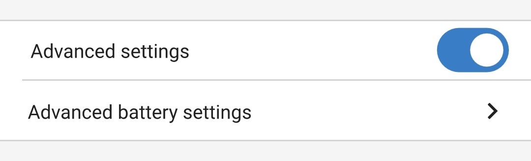
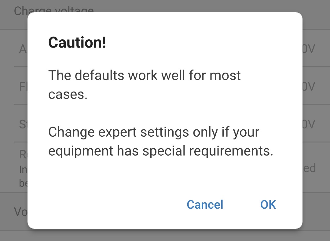
Toggle the Advanced settings switch on to enable the Advanced settings page.

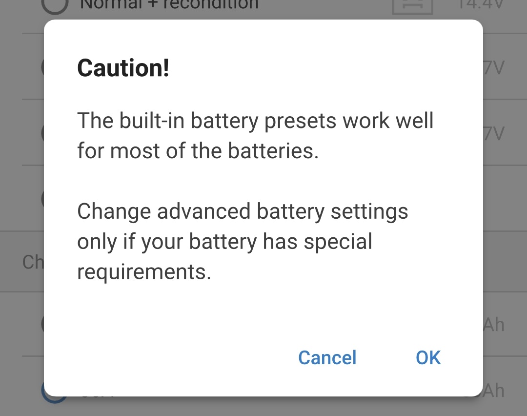
Read the warning message and then select OK to proceed.
Select Advanced battery settings to access the Advanced settings page.
To configure user defined advanced settings:
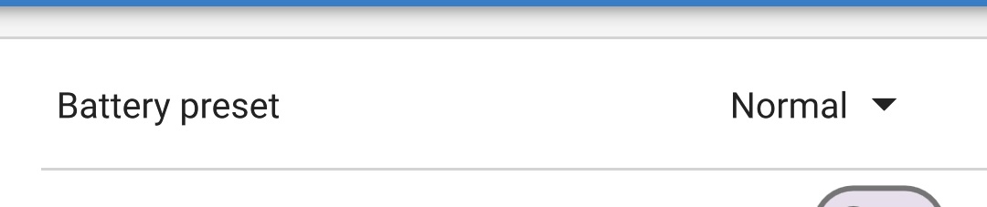
Select the Battery preset dropdown arrow to expand the dropdown menu.
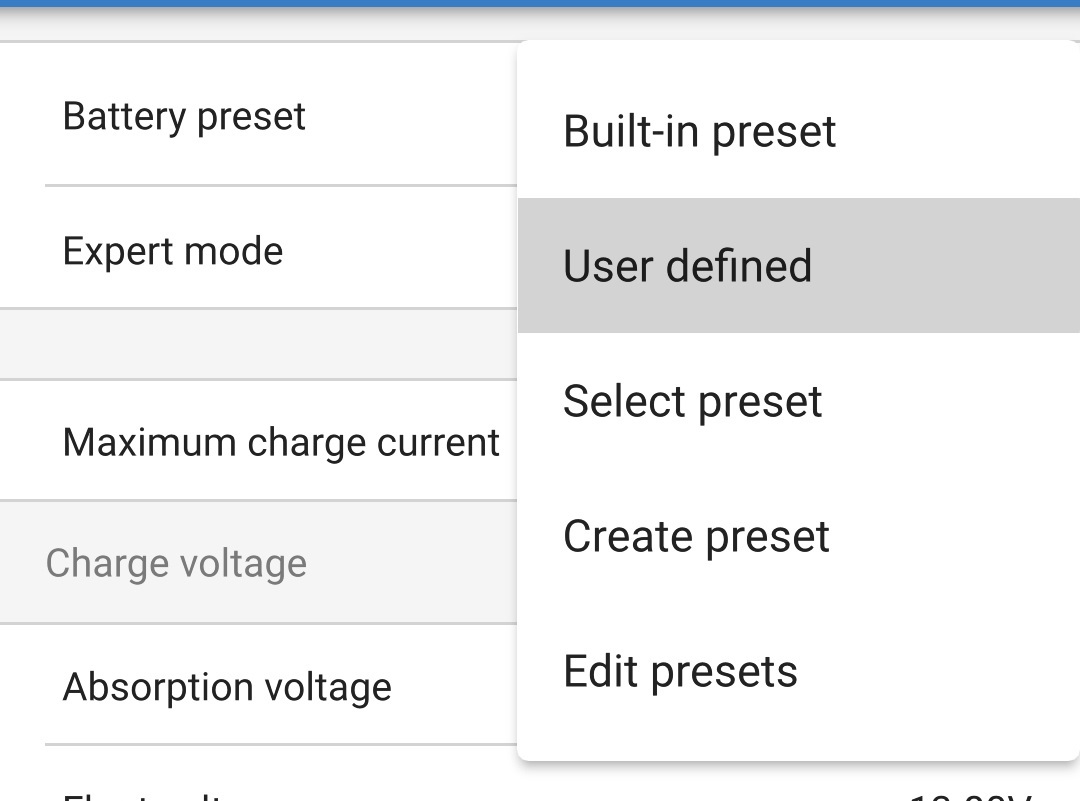
Select User defined from the Battery preset dropdown menu.
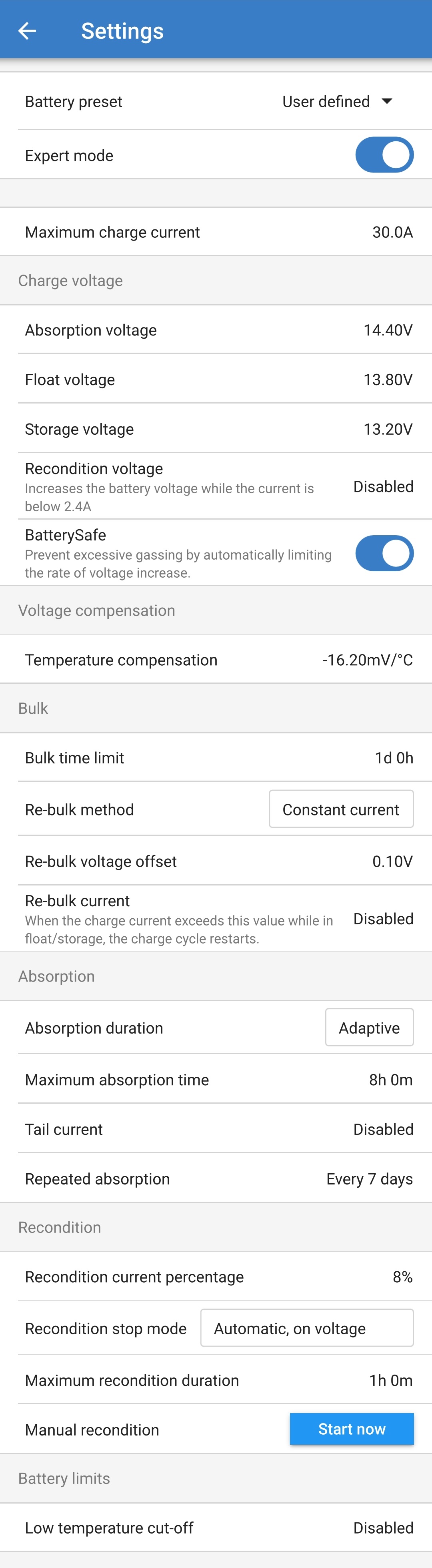
User defined configuration will now be enabled.

Configure the advanced settings as required per battery manufacturers recommendations.
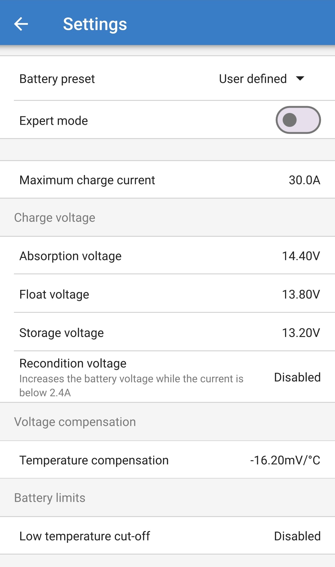
The advanced settings (with expert mode disabled) include:
Battery preset
The Battery preset dropdown allows selection from the following options:
Built-in preset
Selection of a standard integrated pre-set (same as the general settings menu)
User defined
Configuration of user defined charge settings and selection of the last user defined configuration
Select preset
Selection from an extended range of integrated battery charging pre-sets, including new user defined charging pre-sets
Create preset
A new charging preset to be created and saved from user defined settings
Edit presets
An existing preset to be edited and saved
Maximum charge current
The maximum charge current setting allows selection between the default and a significantly reduced charge current limit preset; Maximum, Low (50% of maximum) or Minimum (25% of maximum) current. Alternatively a user defined maximum charge current (between the minimum and maximum limits) can be configured.
Charge voltage
The charge voltage settings enable the voltage setpoint for each charge stage to be independently configured and some charge stages (recondition and float) to be disabled or enabled.
The charge voltage setpoint can be configured for the following charge stages:
Absorption
Float
Storage
Recondition
Voltage compensation
Temperature compensation
The temperature compensation setting enables the charge voltage temperature compensation coefficient to be configured, or temperature compensation to be totally disabled (such as for Li-ion batteries). The temperature compensation coefficient is specified in mV/°C and applies to the entire battery/battery bank (not per battery cell).
Battery limits
Low temperature cut-off
The low temperature cut-off setting disables charging in low temperature conditions to protect Lithium batteries from damage; this setting requires battery temperature to be provided by a compatible battery monitor via VE.Smart networking.
8.2. Expert mode settings
Expert mode expands the advanced settings menu even further, to include more specialised expert level configuration settings.
To access the expert mode settings:
Open the Advanced setting page and enable User defined configuration - see the 'Advanced configuration > Advanced settings' section for instructions.
Toggle the Expert mode switch on to enable additional Expert mode settings (extension of the Advanced settings menu).

Read the warning message and then select OK to proceed.
The Expert mode settings (extension of the Advanced settings menu) will now be accessible.

The ADDITIONAL expert mode settings include:
Charge voltage
BatterySafe
The BatterySafe setting allows the BatterySafe voltage control to be enabled or disabled. When BatterySafe is enabled, the rate of battery voltage increase during bulk stage is automatically restricted to a safe level. In cases where the battery voltage would otherwise increase at a faster rate, the charge current is reduced to prevent excessive gassing.
Bulk
Bulk time limit
The bulk time limit setting restricts the maximum time the charger can spend in bulk stage as a protection measure, since the absorption voltage should have been achieved by this time. If the bulk time limit is satisfied the charger will move directly to float stage.
Re-bulk method
The re-bulk method setting allows selection between constant current or battery voltage method to trigger the charger back into bulk charge stage. When the charger is configured in a VE.Smart network with multiple chargers this setting is overridden and battery volatage is used.
Re-bulk voltage offset
The re-bulk voltage offset setting is used to determine the re-bulk voltage threshold that will trigger a new charge cycle; the offset is relative to the configured Storage voltage (re-bulk voltage = storage voltage - re-bulk voltage offset). If the battery voltage falls below re-bulk voltage threshold while the charger is in float or storage stage and remains below it for one minute, the charger will move back into bulk charge stage.
Re-bulk current
The re-bulk current setting is the charge current limit that will trigger a new charge cycle. If the charge current exceeds the re-bulk current threshold for four seconds while the charger is in float or storage stage, the charger to move back into bulk charge stage.
Note that even when the re-bulk setting is disabled, re-bulk will still occur if the charge current is maintained at the maximum charge current for four seconds while the charger is in float or storage stage.
Absorption
Absorption duration
The absorption duration setting allows selection between adaptive absorption time (calculated based on the bulk time / level of discharge) or a fixed absorption time.
Maximum absorption time / Absorption time
The maximum absorption time / absorption time setting enables the maximum adaptive absorption time or the fixed absorption time to be configured (depending if adaptive or fixed absorption time is selected). Note that regardless if adaptive or fixed absorption time is selected, the absorption phase can end early based on the tail current setting (if enabled).
Tail current
The tail current setting enables the absorption stage to be ended early based on charge current. If the charge current drops below the tail current threshold for one minute, the absorption stage will immediately end and the charger will move to float or storage stage.
Repeated absorption
The repeated absorption setting enables the elapsed time between each automatic refresh charge cycle (1h in absorption stage) to be configured. Repeated absorption is enabled by default and can be disabled which results in the battery staying in storage mode indefinitely.
Recondition
Recondition current percentage
The recondition current percentage is used to establish the charge current limit while the charger is in recondition stage; the percentage is relative to the configured Maximum charge current. The charger will limit charge current to this lower level while in recondition stage.
Recondition stop mode
The recondition stop mode setting allows selection between the recondition stage being ended upon the battery voltage reaching the recondition stage voltage setpoint or a fixed time period.
Maximum recondition duration
The recondition time setting enables the maximum recondition time or the fixed recondition time to be configured (depending on the recondition stop mode selected).
Manual recondition
Manual recondition can be started by selecting on the START NOW button. The duration of the recondition cycle is limited to a maximum of 1 hour.
8.3. VE.Smart Networking
The Blue Smart IP22 Charger range feature VE.Smart networking capability, which enables Bluetooth communication between compatible Victron products to optimise charger operation and battery performance/life; refer to the 'Operation > VE.Smart Networking' section for more information.
VE.Smart networking needs to be enabled and configured using a Bluetooth enabled device (mobile phone or tablet) with the VictronConnect app.
8.3.1. Voltage, temperature and current sense
To setup a VE.Smart Network with Volt-Sense / Temp-Sense / Current-Sense:
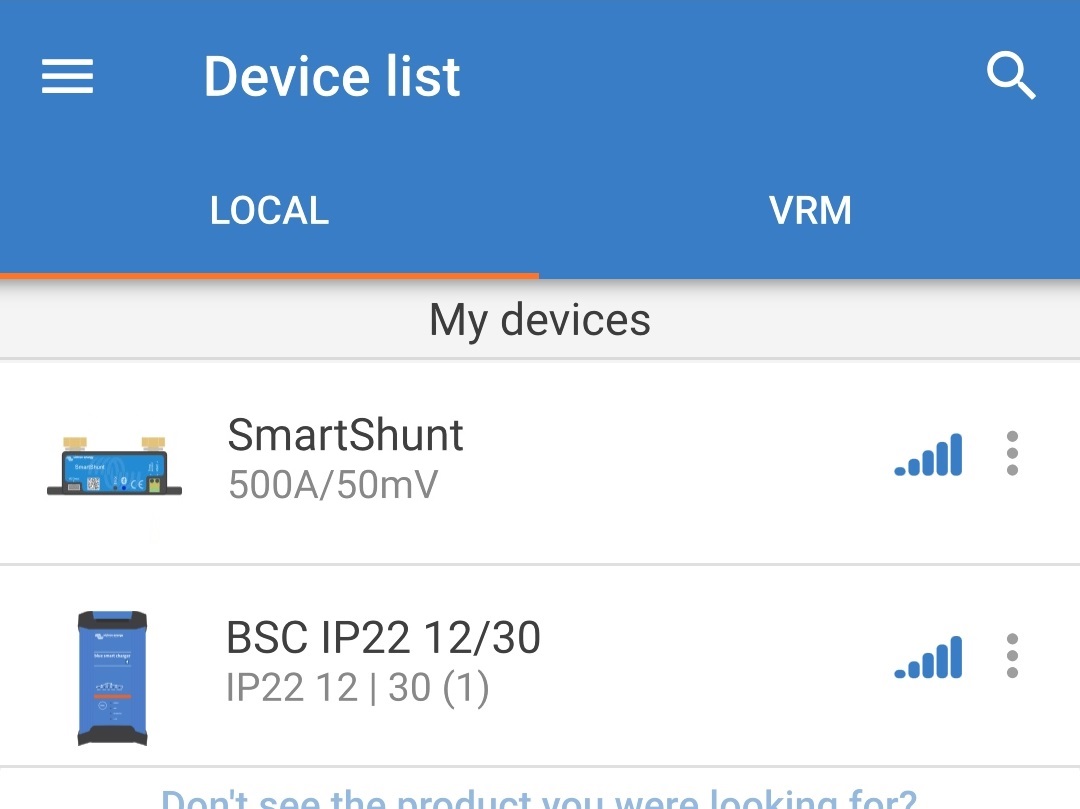
Using a Bluetooth enabled device (mobile phone or tablet), open the VictronConnect app and locate the battery monitor (BMV, SmartShunt, Smart Battery Sense or VE.Bus Smart Dongle) in the Device list Local page, then connect to the device (the default PIN code is stated on a label located on the battery monitor, or try 000000 if there is no label).
Select the Settings icon (gear in the top right corner) to access the Settings page.

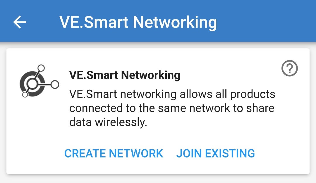
Select VE.Smart networking to access the VE.Smart networking page.

Select CREATE NETWORK (or JOIN NETWORK if a VE.Smart network has already been created).
Enter a name to identify the VE.Smart network and then select OK.
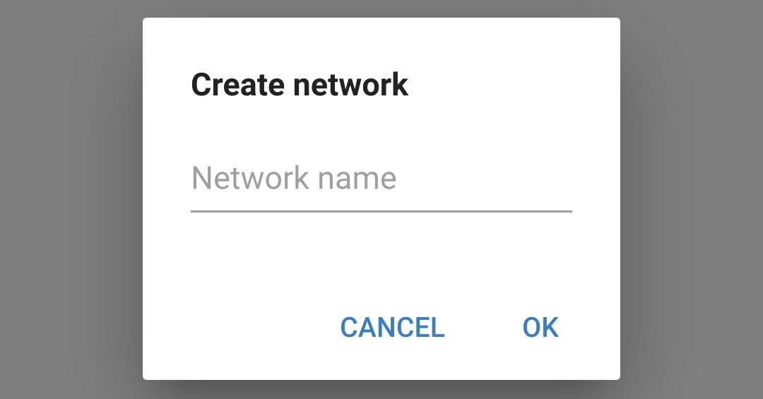
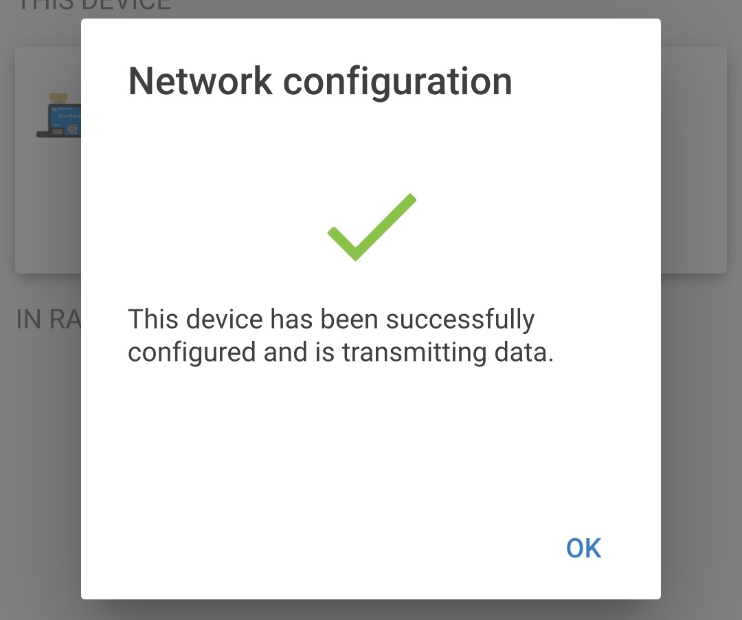
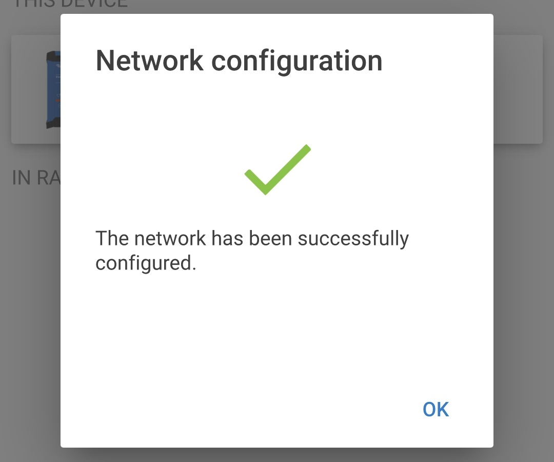
After a short delay a pop-up dialog box will appear confirming that the network has been successfully configured; select OK to close the dialog box.
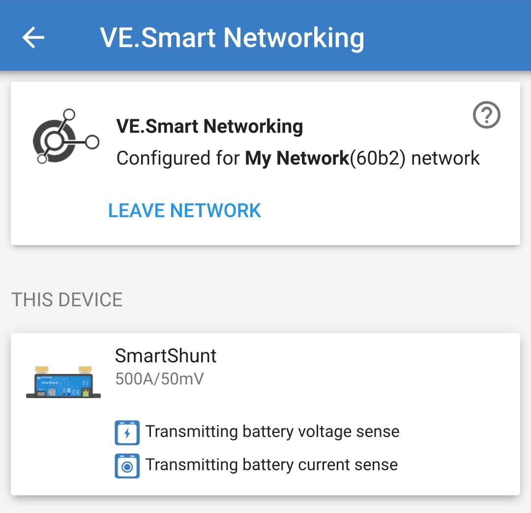
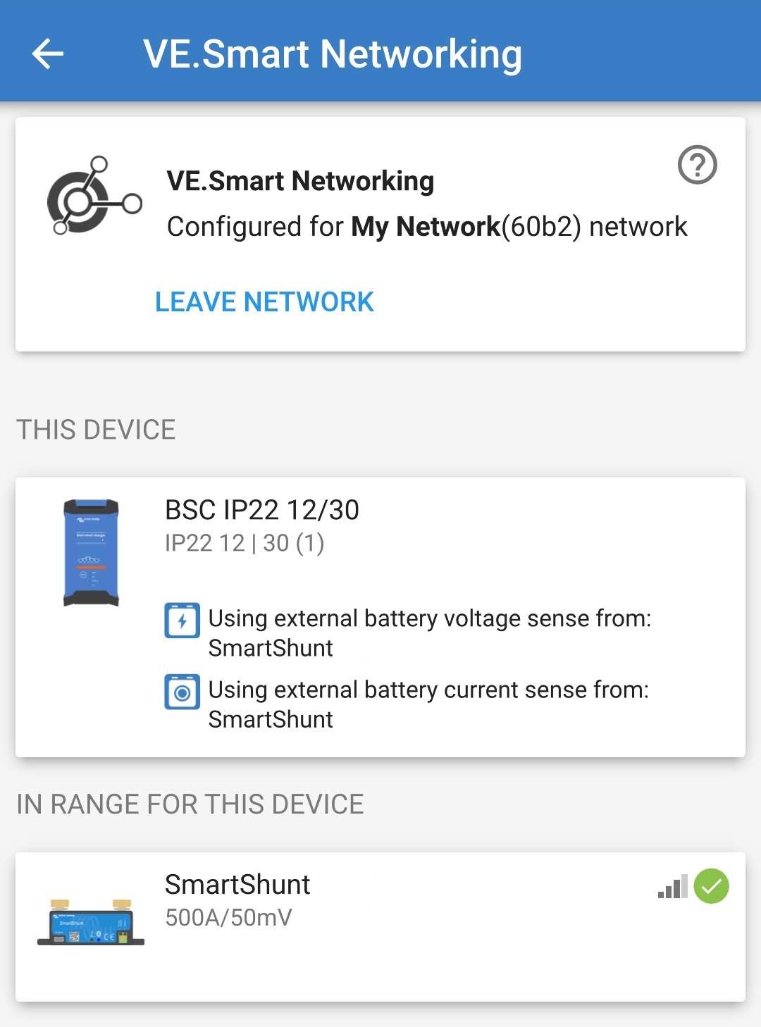
The VE.Smart network configuration details are displayed within the the VE.Smart networking page.
End the current Bluetooth session by exiting into the VictronConnect Device list Local page.
Connect the Blue Smart IP22 Charger AC power cable to a mains power outlet; after a short delay the LEDs indicating the current charge mode and charge state will illuminate.
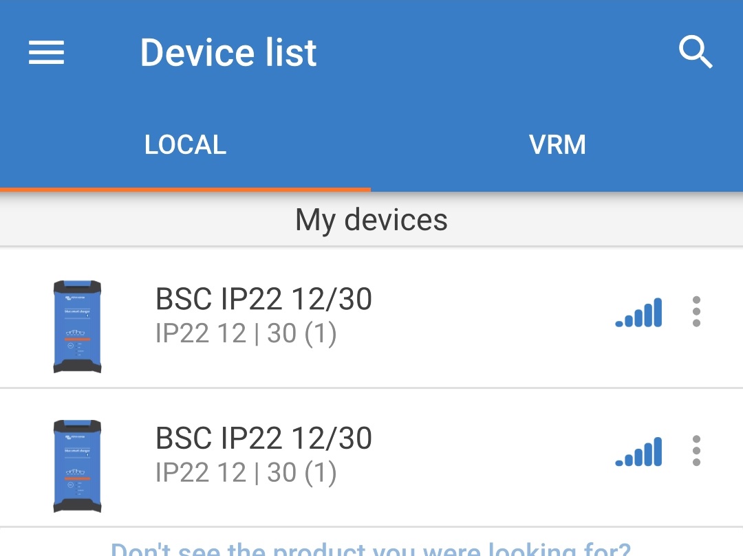
Using a Bluetooth enabled device (mobile phone or tablet), open the VictronConnect app and locate the Blue Smart IP22 Charger (or other VE.Smart networking compatible charger) in the Device list Local page, then connect to the device (the default PIN code is stated on a label located on the back of the charger, or try 000000 if there is no label).
Select the Settings icon (gear in the top right corner) to access the Settings page.
Select VE.Smart networking to access the VE.Smart networking page.
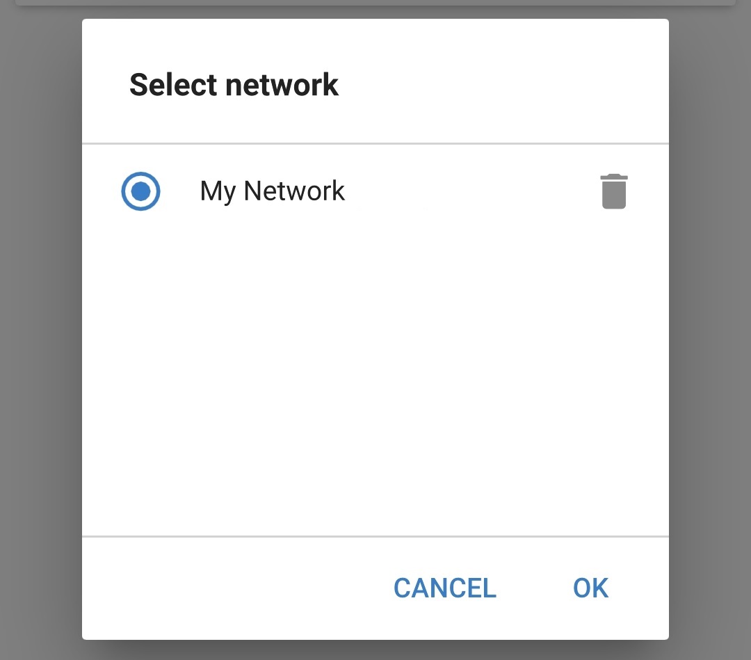
Select JOIN EXISTING.
Select the existing VE.Smart network you want to join, then select OK.
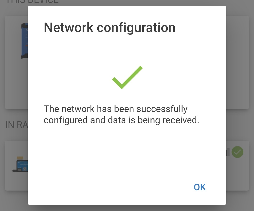
After a short delay a pop-up dialog box will appear confirming that the network has been successfully configured; select OK to close the dialog box.
The VE.Smart network configuration details are displayed within the the VE.Smart networking page.
For systems with additional VE.Smart networking compatible chargers connected to the same battery / battery bank, repeat steps 8 to 16 above to include each remaining charger into the common VE.Smart network.
VE.Smart networking has now been configured; when VE.Smart networking is enabled:
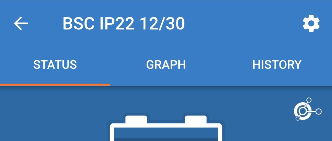
The VE.Smart network symbol will appear in the top right corner of the Status screen (of all devices within the VE.Smart network).
The active charge state LED on the charger (BULK, ABS, FLOAT and STORAGE) will blink (turn off) momentarily every 4 seconds.

Notice
Multiple chargers in a common VE.Smart network must all have the same charge settings, since the master can change dynamically.
8.3.2. Synchronised charging
To setup a VE.Smart Network with Synchronised charging:
Connect all Blue Smart IP22 Charger AC power cables to a mains power outlet; after a short delay the LEDs indicating the current charge mode and charge state will illuminate.
Using a Bluetooth enabled device (mobile phone or tablet), open the VictronConnect app and locate the first Blue Smart IP22 Charger in the Device list Local page, then connect to the device the default PIN code is stated on a label located on the back of the charger, or try 000000 if there is no label).
Select the Settings icon (gear in the top right corner) to access the Settings page.
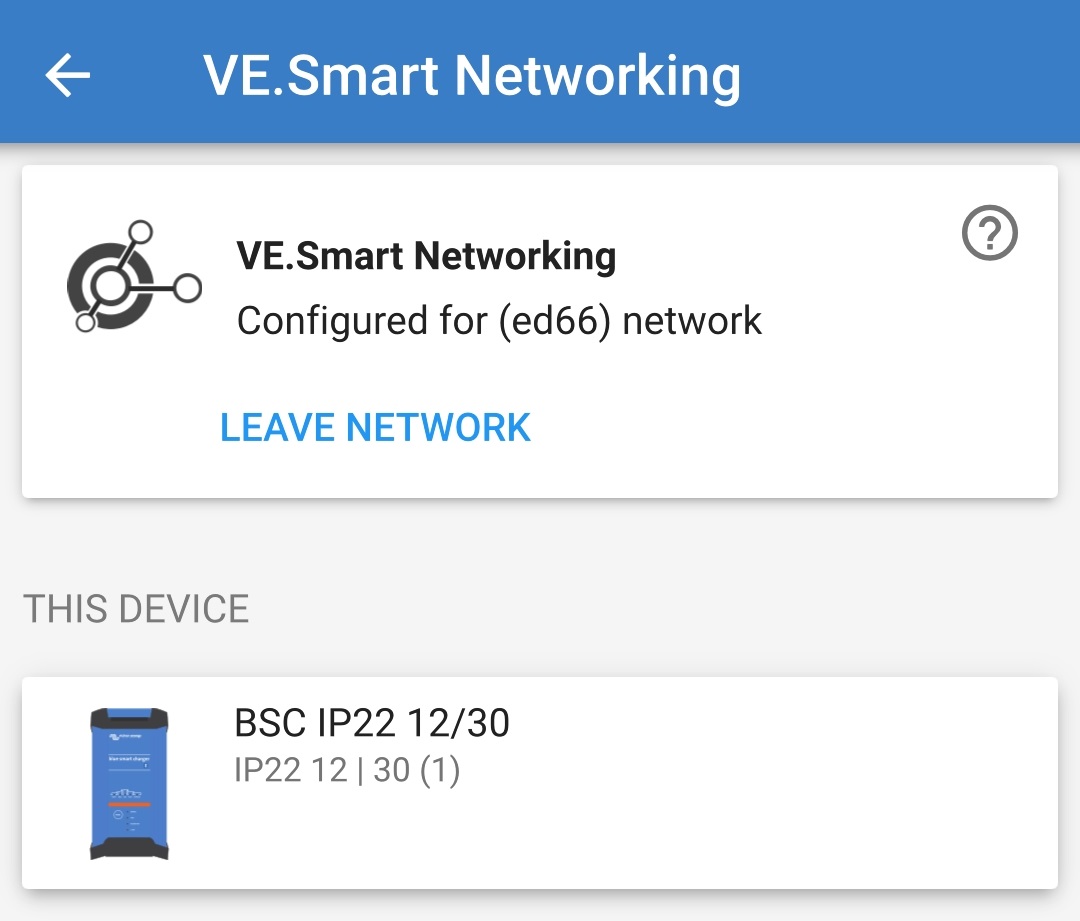
Select VE.Smart networking to access the VE.Smart networking page.
Select CREATE NETWORK (or JOIN NETWORK if a VE.Smart network has already been created).
Enter a name to identify the VE.Smart network and select OK.
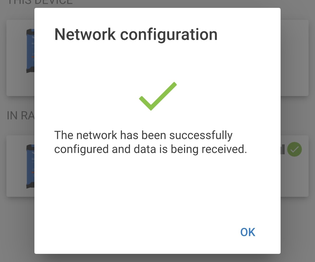
After a short delay a pop-up dialog box will appear confirming that the network has been successfully configured; select OK to close the dialog box.
The VE.Smart network configuration details are displayed within the the VE.Smart networking page.
End the current Bluetooth session by exiting into the VictronConnect Device list Local page.
Using a Bluetooth enabled device (mobile phone or tablet), open the VictronConnect app and locate the subsequent Blue Smart IP22 Charger (or other VE.Smart networking compatible charger) in the Device list Local page, then connect to the device (the default PIN code is stated on a label located on the back of the charger, or try 000000 if there is no label).
Select the Settings icon (gear in the top right corner) to access the Settings page.
Select VE.Smart networking to access the VE.Smart networking page.
Select JOIN EXISTING.
Select the existing VE.Smart network you want to join, then select OK.
After a short delay a pop-up dialog box will appear confirming that the network has been successfully configured; select OK to close the dialog box.
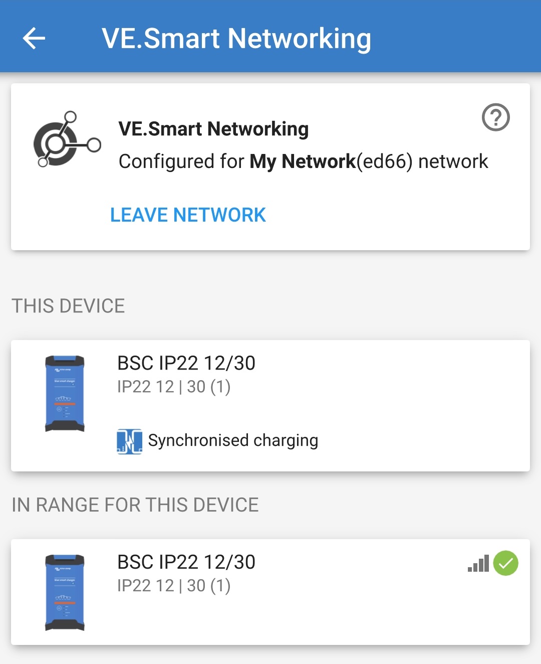
The VE.Smart network configuration details are displayed within the the VE.Smart networking page.
For systems with additional VE.Smart networking compatible chargers connected to the same battery / battery bank, repeat steps 9 to 17 to include each remaining charger into the common VE.Smart network.
VE.Smart networking has now been configured; when VE.Smart networking is enabled:
The VE.Smart network symbol will appear in the top right corner of the STATUS screen (of all devices within the VE.Smart network).
The active charge state LED on the charger (BULK, ABS, FLOAT and STORAGE) will blink (turn off) momentarily every 4 seconds.
Notice
Multiple chargers in a common VE.Smart network must all have the same charge settings, since the master can change dynamically.
8.4. Power supply mode
The Blue Smart IP22 Charger range is also suitable for use as a DC power supply, to directly power loads with or without a battery connected.
When the charger is used specifically as a DC power supply it is recommended to activate Power supply mode, which will disable the internal charge logic and provide a constant (configurable) DC voltage to the loads.
To enable power supply mode:
Connect the Blue Smart IP22 Charger AC power cable to a mains power outlet; after a short delay the LEDs indicating the current charge mode and charge state will illuminate.
Using a Bluetooth enabled device (mobile phone or tablet), open the VictronConnect app and locate the Blue Smart IP22 Charger in the Device list Local page, then connect to the device (the default PIN code is stated on a label located on the back of the charger, or try 000000 if there is no label).
Select the Settings icon (gear in the top right corner) to access the Settings page.
Select the Charger in the Function filed to open the Function pop-up dialog box.
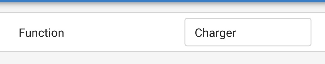
Select Power supply from the Function pop-up dialog box, then select OK.
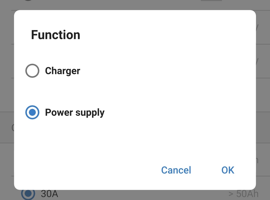
After a short delay the BULK, ABS, FLOAT and STORAGE LEDs will be illuminated to indicate the charger function has changed to Power supply mode.

If required, adjust the desired output voltage and/or the maximum current limit.
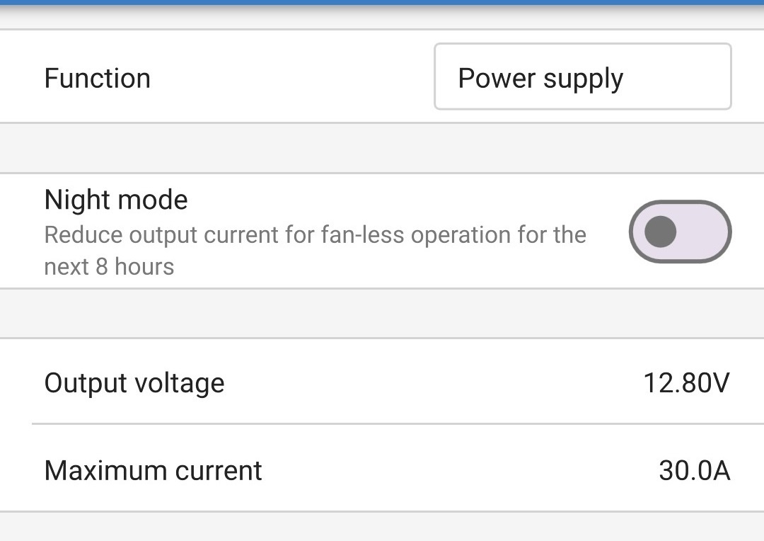
Power supply mode has now been enabled and configured.
To revert the charger function back to use as a normal battery charger, follow steps 1 to 4 above and then select Charger from the Function pop-up dialog box.