5. Installation
5.1. Mounting
The Blue Smart IP22 Charger range is designed to be permanently mounted using the mounting tabs on the base of the charger.
Before mounting, the following aspects should be considered to identify/provide a suitable and safe location:
Install the charger in a location with good natural airflow/ventilation; in case airflow is a restricted, consider adding a cooling fan.
Ensure there is sufficient unobstructed space around the charger; a minimum clearance of 100mm above and below is recommended.
Install the charger on a non-flammable substrate and ensure there are no heat-sensitive items in the immediate vicinity; it is normal for the charger to become hot during operation.
Install the charger in a location where it is protected from environmental conditions such as water, high moisture and dust, and also located well away from any flammable liquids or gasses.
Do not install or place/operate the charger on top of the battery, directly above the battery, or in a sealed compartment with the battery; batteries can emit explosive gasses.
Do not cover or place any other items on top of the charger.
Mount the Blue Smart IP22 Charger vertically with the terminals facing down; secure using suitable screws though the mounting holes/slots.
Select and use screws with a pan/flange head (do not use screws with a countersunk/tapered head), and a screw thread outer diameter well matched to the mounting hole/slot internal diameter (~4mm max OD to provide a clearance fit).
To aid installation, it is recommended to support the unit using the 2 lower screws (leave the screw heads ~3mm from the surface) and then install the 2 upper screws, before fully securing all 4 screws.
Take care to not over-tighten the mounting screws (as the mounting flanges are plastic), and to not damage the AC power cable while securing the lower left mounting screw (as the AC power cable is located directly above it).
Refer to the drawing below for mounting dimensions:

5.2. Wiring
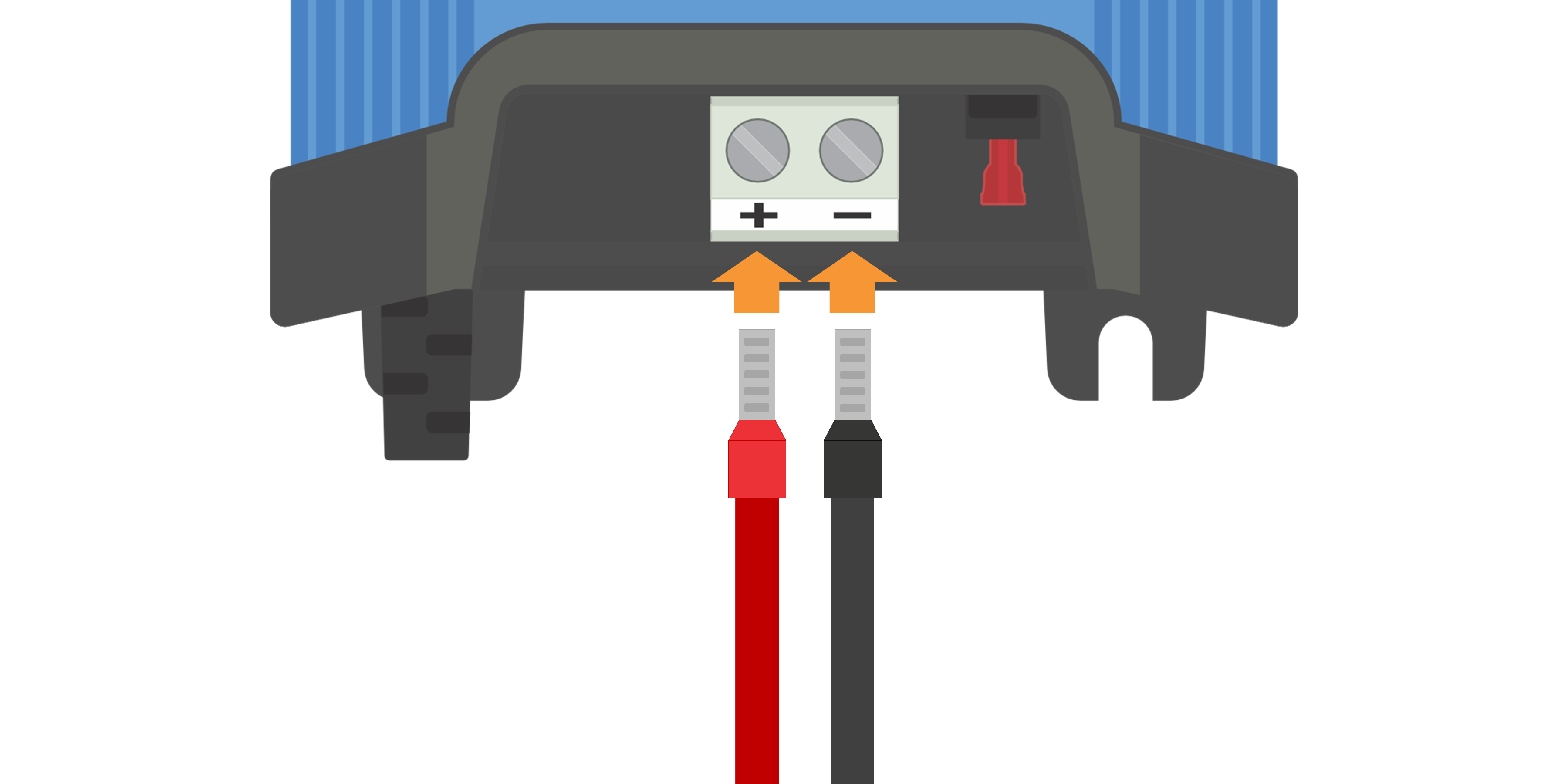
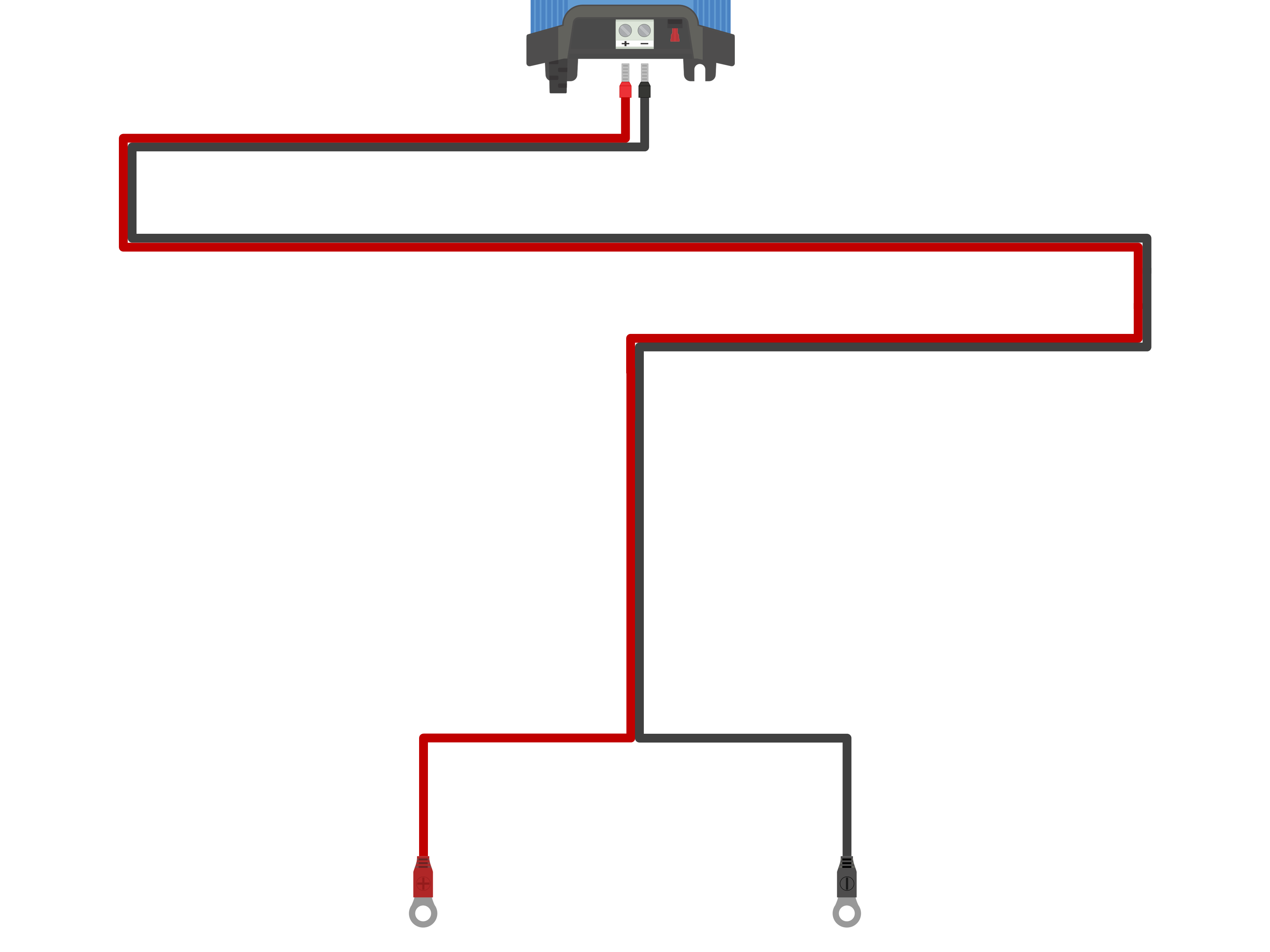
Connect suitable DC power cabling to the Blue Smart IP22 Chargers BATTERY terminals.
Remove the terminal cover by gently applying outward pressure on the cover upper face.

Prepare flexible multi stranded copper DC power cable with sufficient cross sectional area; refer to the 'Installation > Wiring > DC power cable' section for more information.
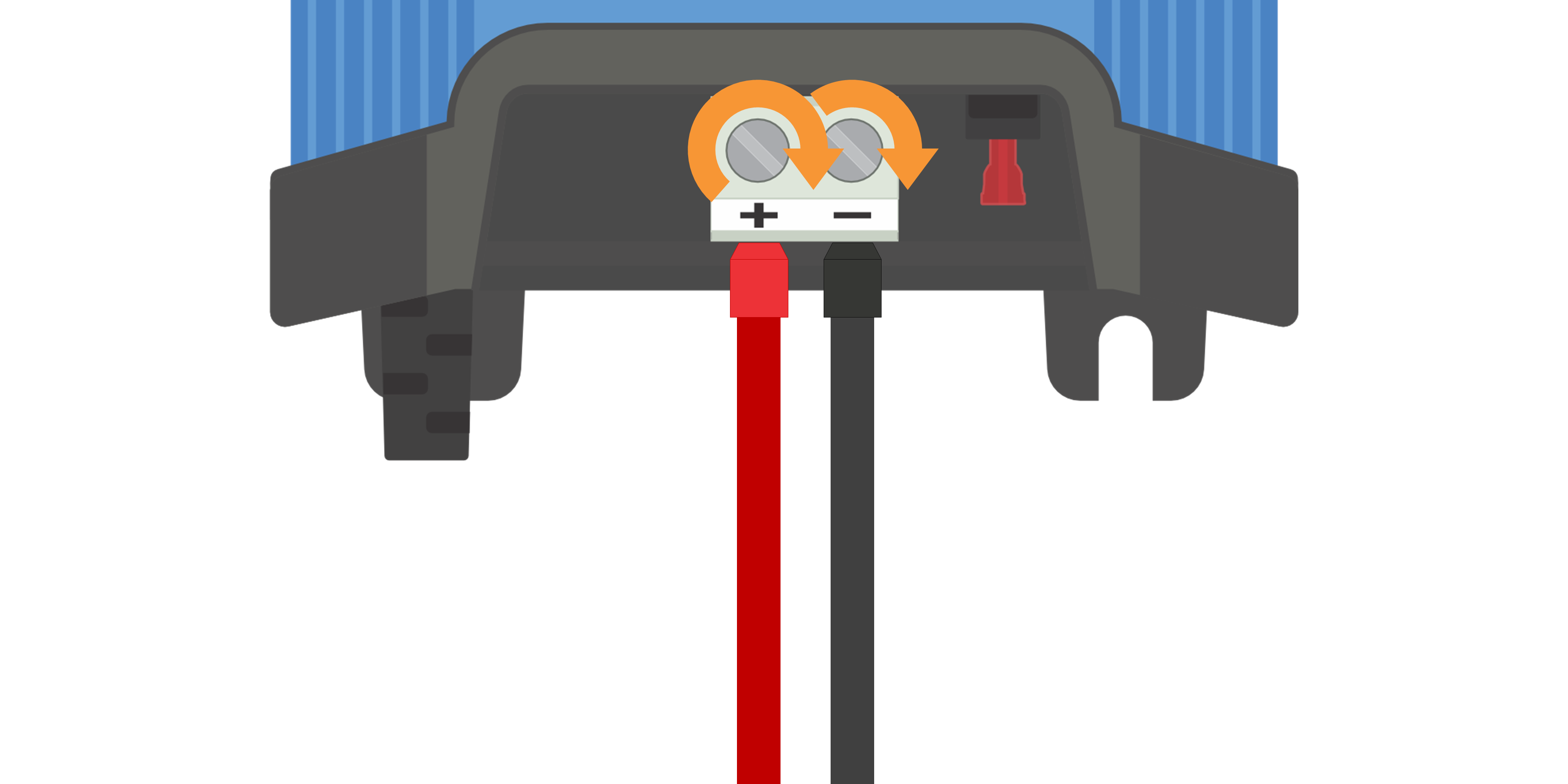
Connect the positive DC cable (red insulation) to the positive (+) terminal and the negative DC cable (black insulation) to the negative (-) terminal connection; ensure that the cable connection polarity is correct.
Torque the terminal screws to 2.4Nm using a suitable torque wrench and screw driver bit, then reinstall the terminal cover.
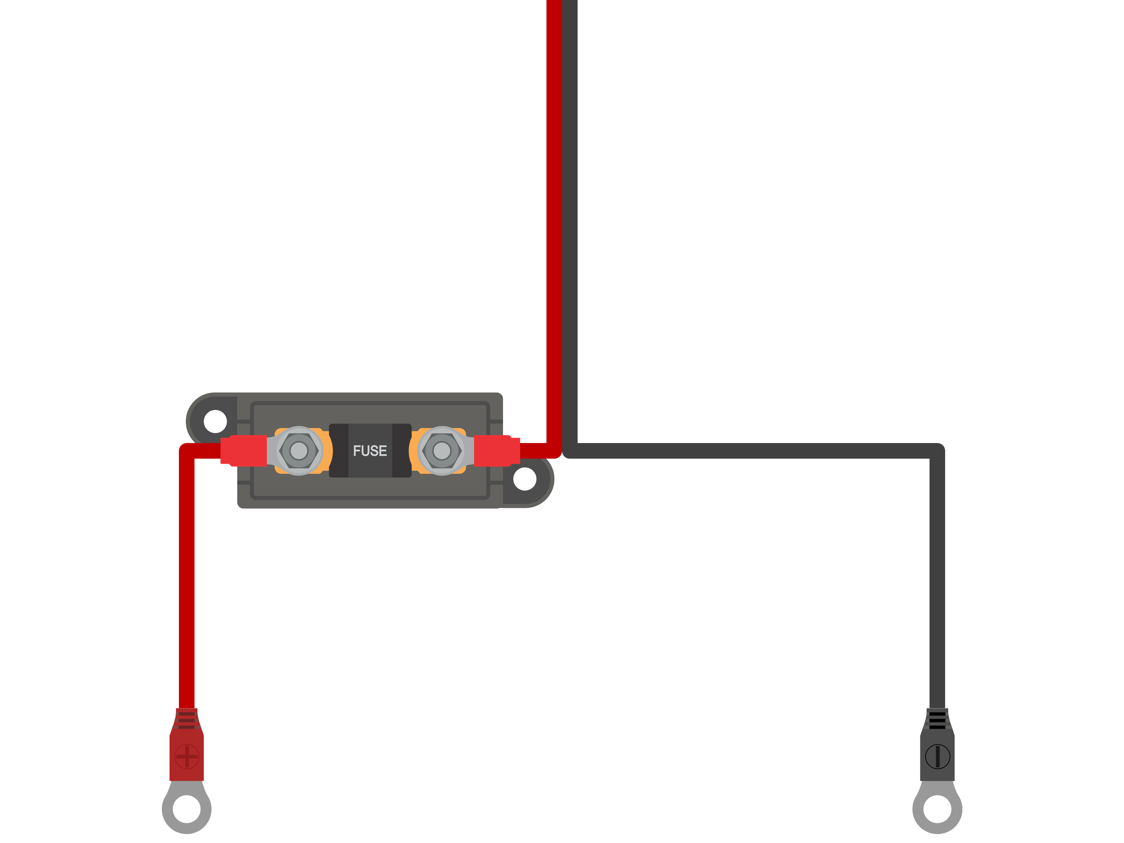
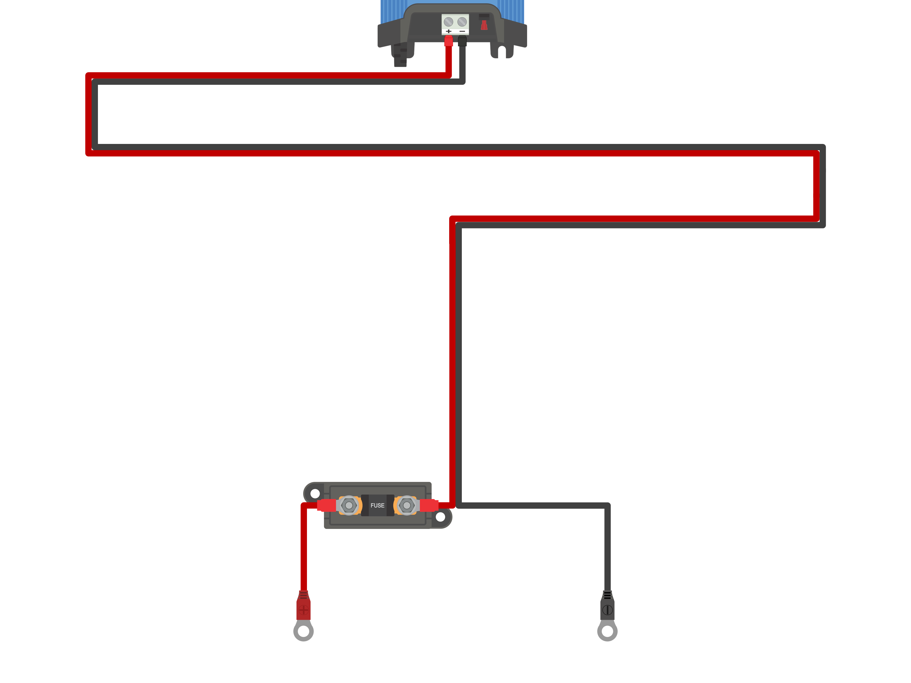
Install a suitably rated inline fuse or circuit breaker within the DC power cabling between the Blue Smart IP22 Charger and battery/batteries, located as close as practical to the battery/batteries; refer to the 'Installation > Wiring > Overcurrent protection' section for more information.
Connect the DC power cabling to the battery/batteries or DC system distribution bus - follow the instructions relevant to the installation type.
For hardwired installations, or when charging a battery outside of a vehicle/installation:
Ensure that the DC system is shut down (all DC loads and charge sources off/isolated) prior to disconnection of any existing battery / DC system distribution bus cabling and connection of the charger to the battery terminals / DC system distribution bus.
Connect the positive DC cable (red insulation) to the positive (+) terminal and the negative DC cable (black insulation) to the negative (-) terminal connection; ensure that the cable connection polarity is correct.
Torque all wiring termination hardware to manufacturers torque specifications using a suitable torque wrench and socket / screw driver bit.
For temporary installations when charging a battery installed within a vehicle, and the negative (-) battery terminal is grounded to the vehicle chassis (conventional):
Connect the positive DC cable / battery clamp (red insulation) directly to the battery positive (+) terminal first.
Then connect the negative DC cable / battery clamp (black insulation) to a suitable grounding point on the vehicle chassis (not directly to the negative battery terminal).
When disconnecting the charger, disconnect the DC cables / battery clamps in reverse of the connection order.
For temporary installations when charging a battery installed within a vehicle, and the positive (+) battery terminal is grounded to the vehicle chassis (unconventional):
Connect the negative DC cable / battery clamp (black insulation) directly to the battery negative (-) terminal first.
Then connect the positive DC cable / battery clamp (red insulation) to a suitable grounding point on the vehicle chassis (not directly to the positive battery terminal).
When disconnecting the charger, disconnect the DC cables / battery clamps in reverse of the connection order.
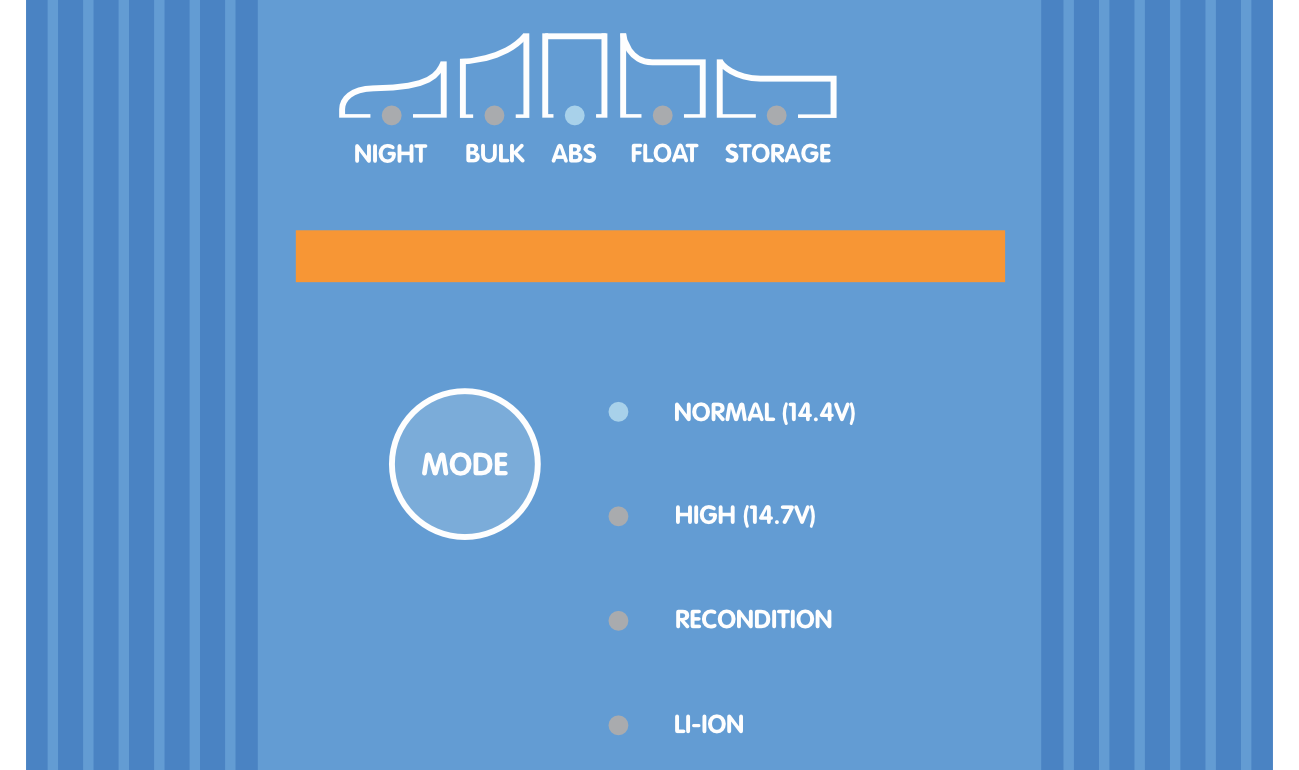
Connect the Blue Smart IP22 Charger AC power cable to a mains power outlet; after a short delay the LEDs indicating the current charge mode and charge state will illuminate.
Notice
Example wiring schematics depicting most typical installation configurations are also provided for reference; refer to the 'Installation > Schematics' section for more information.
5.2.1. DC power cable
The Blue Smart IP22 Charger range features rising clamp screw terminals for connection to DC power cabling, which is not included and needs to be supplied by the installer.
To ensure optimal and reliable operation, it is important to select high quality flexible DC power cabling that is suitable for the specific charger model and the overall installation; DC power cable selection should consider the following aspects:
Cable size/gauge
Conductor cross sectional area is proportional to the resistance of a cable per unit length, which effects the amount of heat generated per unit length and the voltage drop over the total cable length.
Current carrying capacity
Current carrying capacity is the maximum current a cable size/gauge can carry in a particular installation environment without exceeding the temperature limit of the cable insulation; accordingly current carrying capacity is dependent on cable size/gauge, the installation environment and the insulation temperature limit.
To prevent overheating of the DC power cable and/or interfacing equipment, the maximum current rating for the selected cable size/gauge (including any de-rating applicable to the installation) must exceed the maximum normal operating current and also the rating of the fuse or circuit breaker installed (in case of an overcurrent fault).
Voltage drop %
Voltage drop percentage is the maximum voltage lost over the cable length, expressed as a percentage in relation to the nominal operating voltage; accordingly voltage drop % is dependent on cable size/gauge, total cable length and the nominal operating voltage.
To prevent excessive power loss and operational issues due to high voltage drop, design the system layout to minimise DC power cable length and select a cable size/gauge that provides a voltage drop of 3% or less (at maximum normal operating current).

Conductor
The conductor material and specifications effect the resistance of a cable per unit length (effecting current carrying capacity), the resistance and heat generated at terminations, and overall cable flexibility.
Conductor material and configuration
Use high quality flexible DC power cabling that consists of fine multi-stranded oxygen free copper conductors.
Strand diameter
Strand diameter effects the contact area and accordingly the resistance at terminations; a high resistance termination will generate substantial heat when operating under load and can result in severe overheating.
To maximise contact area at terminations and prevent overheating at/near terminations, the diameter of each individual copper strand must not exceed 0.4mm (0.016 inch) or a surface area of 0.125mm² (AWG26).
Flexibility class
To facilitate installation with practical bend radii and prevent failure of the cable and/or interfacing equipment due to excessive force/stress at terminations and/or cyclic fatigue, use high quality flexible DC power cabling with a flexibility class of 5 - Flexible copper conductors, or 6 - Extra flexible copper conductors.

Insulation
The insulation material and specifications effect the maximum temperature capability/rating (effecting current carrying capacity) and the maximum voltage isolation capability/rating of a cable.
Temperature rating
The insulation temperature rating effects the current carrying capacity of a cable and must not be exceeded when considering the combination of a) maximum ambient temperature, b) the installation environment (which effects the dissipation of heat), and c) temperature rise due the heat generated by the cable when operating at the fuse or circuit breaker current rating.
To prevent overheating of the cable insulation, use high quality flexible DC power cabling with an insulation temperature rating of at least 90°/194°F (preferably 105°C/221°F), or as required for the installation.
Voltage rating
To ensure robust electrical isolation and overall safety, use high quality flexible DC power cabling with an insulation voltage rating that exceeds the maximum operating voltage of the system; high quality flexible DC power cabling typically has an insulation voltage rating of 0.6/1kV.
Refer to the table below for the minimum DC power cable size/gauge (cross sectional area) recommended for each Blue Smart IP22 Charger model, and the installation specific DC power cable length:
Notice
The DC power cable length ranges represent one way length between charger and battery, the total circuit length (positive and negative cable length) has been assumed to be double one way length for the voltage drop calculations.
Certain combinations are "Not recommended" as voltage drop would be excessive even with the largest compatible DC power cable size; in addition to high power loss, excessive voltage drop can cause charging issues.
The DC power cable size/gauge recommendations above are based on cabling with an insulation rating of at least 90°C (194°F) routed within an unenclosed area at 30°C (86°F) ambient temperature and not bundled with other cabling, and a 3% maximum voltage drop limit; these recommendations are generic and do not cover the intricacies of all installations and/or cable types, please consult a certified installer for guidance with specific and/or complex installations.
5.2.2. Overcurrent protection
To ensure reliable and safe operation, it is recommended to install a suitably rated inline fuse or circuit breaker within the DC power cabling between the Blue Smart IP22 Charger and battery/batteries, located as close as practical to the battery/batteries; this is particularly important for hardwired installations.
The primary purpose of an inline fuse or circuit breaker located close to the battery/batteries (energy source) is to protect the cabling and system in the event of a overcurrent fault, such as a short circuit in the DC power cabling; a fuse or circuit breaker located in the charger unit or nearby within the DC power cabling will not provide protection from a short circuit in the unprotected length of cabling.
In the event of a short circuit in the DC power cabling between the battery/batteries and charger, the battery/batteries have the capability to provide extremely high current through the DC power cabling, which can result in severe overheating of the cabling and potentially a fire unless the battery/batteries (energy source) is promptly disconnected by a suitable fuse or circuit breaker.
Refer to the table below for the recommended fuse / circuit breaker rating, depending on the charger model:
Notice
The fuse / circuit breaker rating recommendations above are based on a 75% maximum normal operating current limit for the minimum fuse / circuit breaker rating and the maximum current capability of the related DC power cabling size/gauge for the maximum fuse / circuit breaker rating; these recommendations are generic and do not cover the intricacies of all installations and/or fuse / circuit breaker types, please consult a certified installer for guidance with specific and/or complex installations.
5.3. Schematics
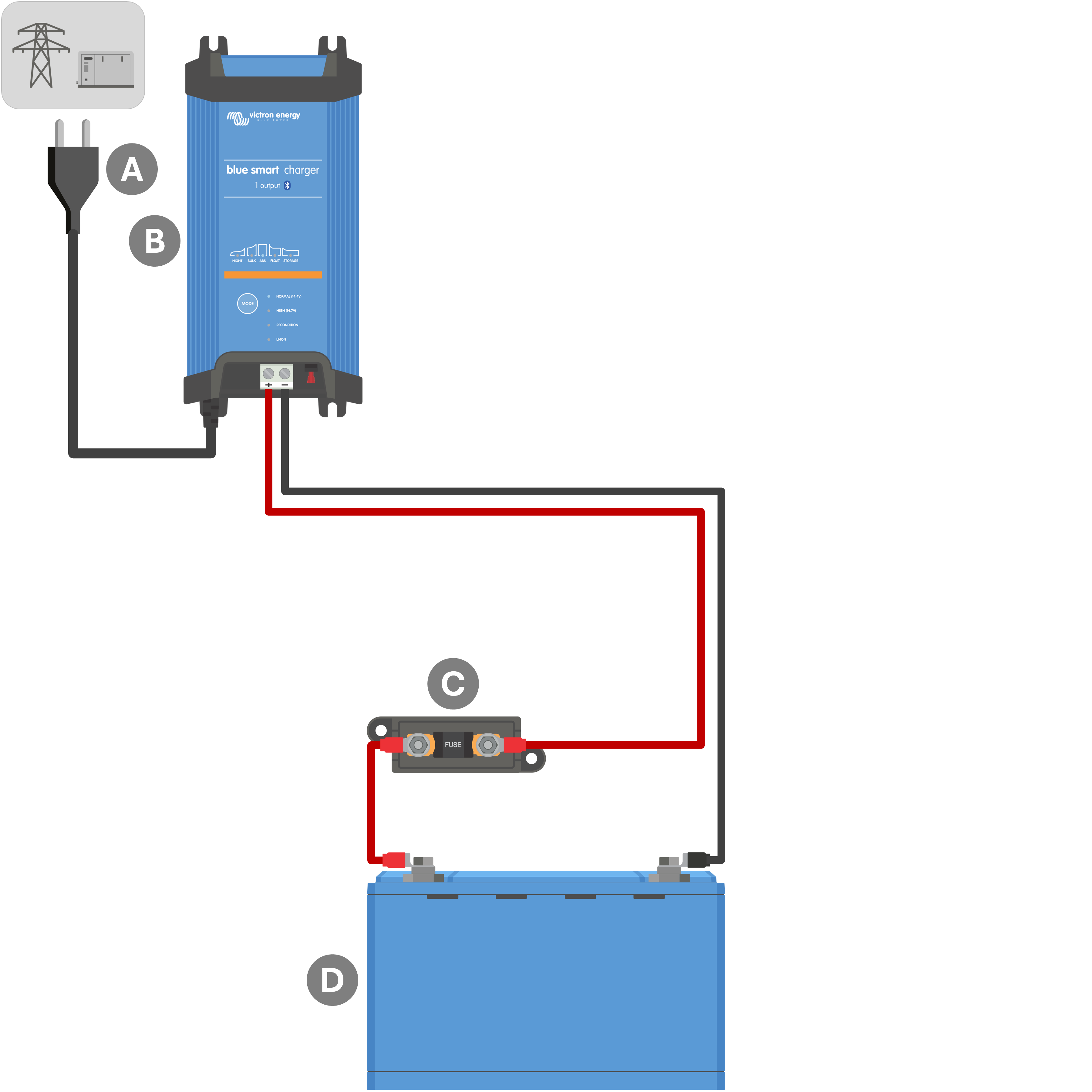
5.3.1. Basic install
Refer to the wiring schematic below to connect a single (1) output Blue Smart IP22 Charger to a single battery / battery bank:
Key | Description |
|---|---|
A | AC power supply (mains power grid, generator or inverter) |
B | Blue Smart IP22 Charger (1 output model) |
C | Fuse / circuit breaker (locate as close as practical to battery) |
D | Battery / battery bank |
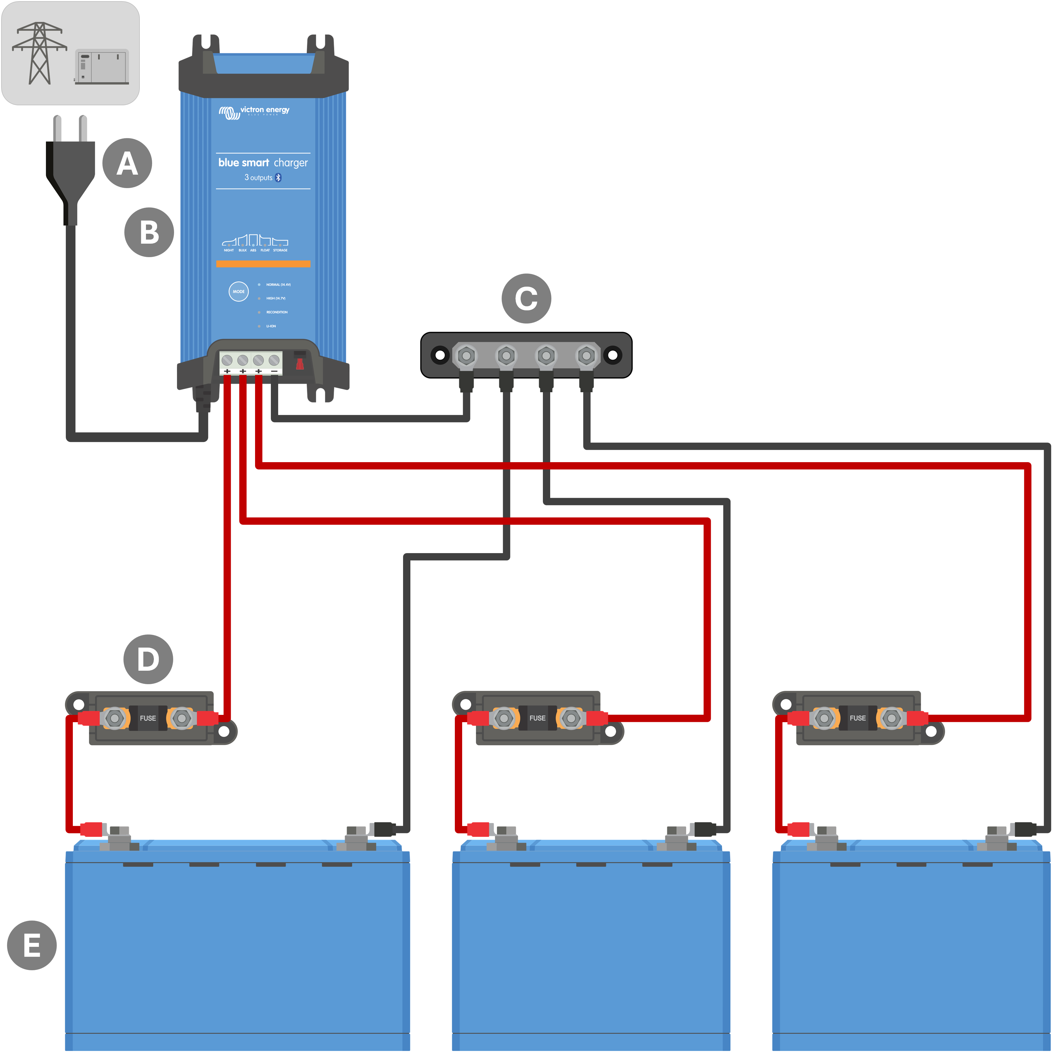
Refer to the wiring schematic below to connect a multiple (3) output Blue Smart IP22 Charger to multiple independent batteries / battery banks:
Key | Description |
|---|---|
A | AC power supply (mains power grid, generator or inverter) |
B | Blue Smart IP22 Charger (3 output model) |
C | DC negative busbar |
D | Fuses / circuit breakers x3 (locate as close as practical to batteries) |
E | Batteries / battery banks x3 (any combination of 1, 2 or 3 batteries) |
5.3.2. System with Smart Battery Sense
Refer to the wiring schematic below to connect a Blue Smart IP22 Charger (1 output model) to a single battery / battery bank, with a Smart Battery Sense in the system:
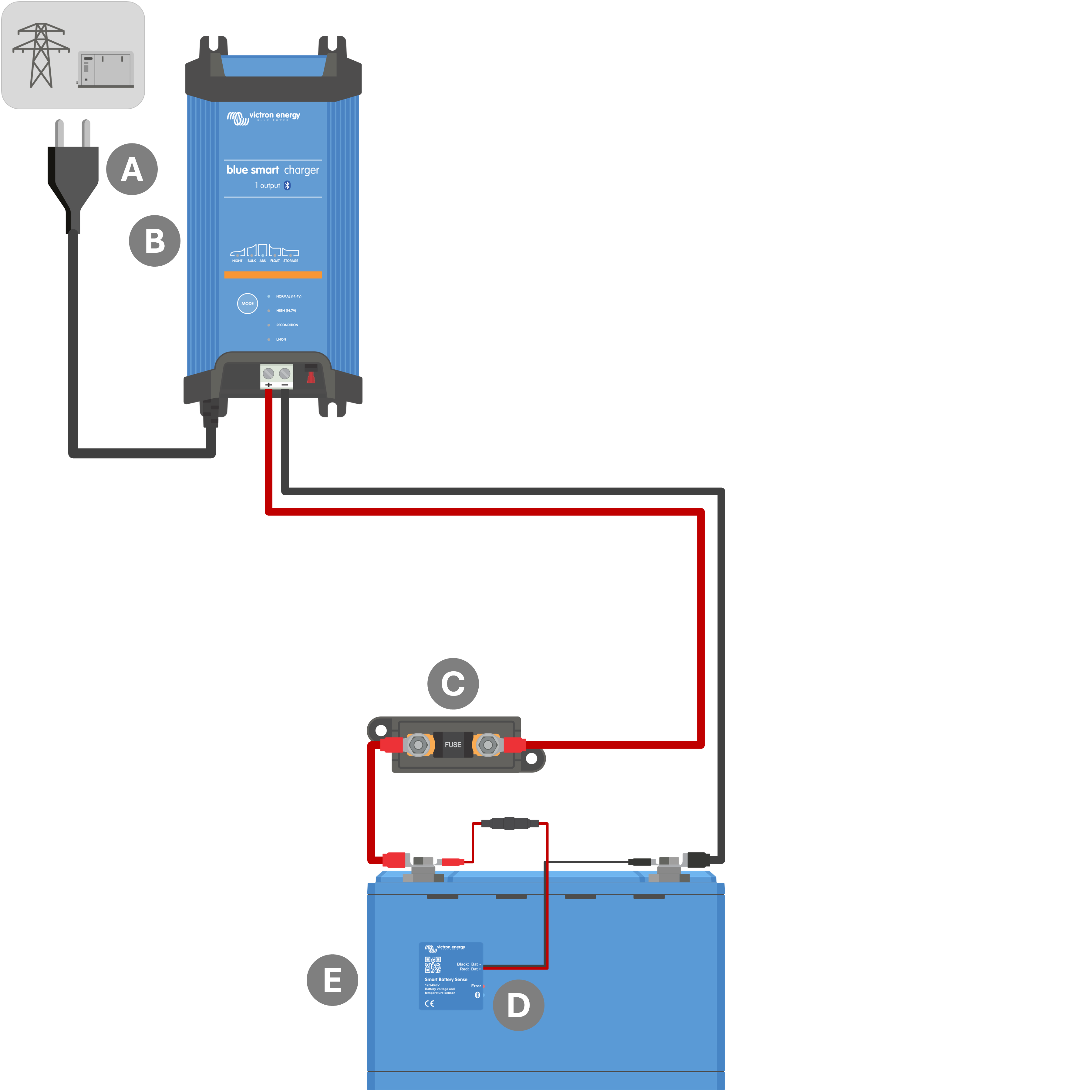
Key | Description |
|---|---|
A | AC power supply (mains power grid, generator or inverter) |
B | Blue Smart IP22 Charger (1 output model) |
C | Fuse / circuit breaker (locate as close as practical to battery) |
D | Smart Battery Sense |
E | Battery / battery bank |
Notice
A VE.Smart Network must be setup between the Blue Smart IP22 Charger and Smart Battery Sense to enable Bluetooth connectivity and communication between devices; refer to the 'Advanced Configuration > VE.Smart Networking’ section for more information.
Refer to the wiring schematic below to connect a Blue Smart IP22 Charger (3 output model) to multiple independent batteries / battery banks, with a Smart Battery Sense in the system:

Key | Description |
|---|---|
A | AC power supply (mains power grid, generator or inverter) |
B | Blue Smart IP22 Charger (3 output model) |
C | DC negative busbar |
D | Fuses / circuit breakers x3 (locate as close as practical to batteries) |
E | Smart Battery Sense |
F | Batteries / battery banks x3 (any combination of 1, 2 or 3 batteries) |
Notice
A VE.Smart Network must be setup between the Blue Smart IP22 Charger and Smart Battery Sense to enable Bluetooth connectivity and communication between devices; refer to the 'Advanced Configuration > VE.Smart Networking’ section for more information.
5.3.3. System with SmartShunt
Refer to the wiring schematic below to connect a Blue Smart IP22 Charger (1 output model) to a single battery / battery bank, with a SmartShunt or BMV battery monitor in the system:
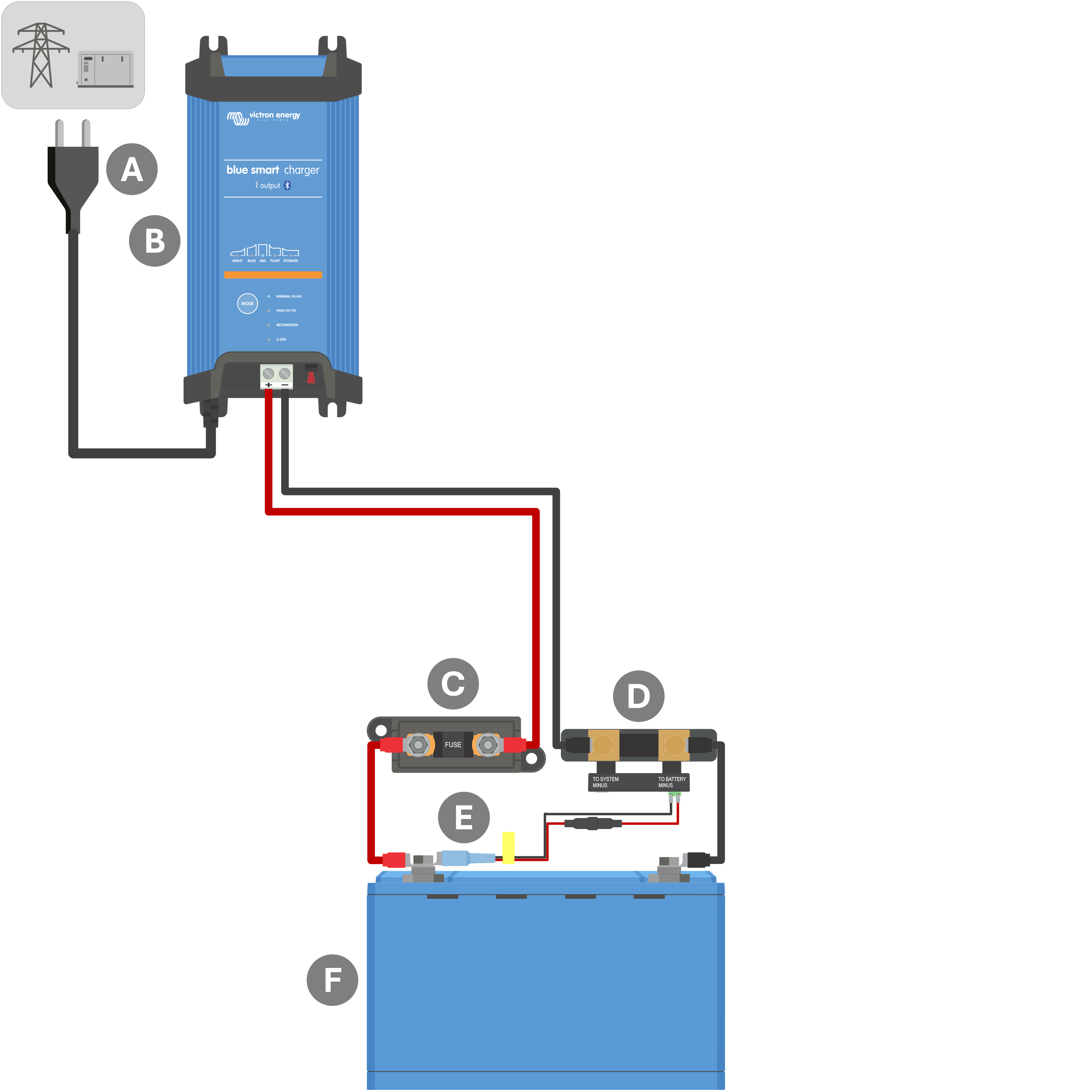
Key | Description |
|---|---|
A | AC power supply (mains power grid, generator or inverter) |
B | Blue Smart IP22 Charger (1 output model) |
C | Fuse / circuit breaker (locate as close as practical to battery) |
D | SmartShunt or BMV battery monitor shunt (locate as close as practical to battery) |
E | Temperature and voltage sensor (Optional accessory, PN: ASS000100000) |
F | Battery / battery bank |
Notice
A VE.Smart Network must be setup between the Blue Smart IP22 Charger and SmartShunt or BMV battery monitor to enable Bluetooth connectivity and communication between devices; refer to the 'Advanced Configuration > VE.Smart Networking’ section for more information.
Refer to the wiring schematic below to connect a Blue Smart IP22 Charger (3 output model) to multiple independent batteries / battery banks, with a SmartShunt or BMV battery monitor in the system:
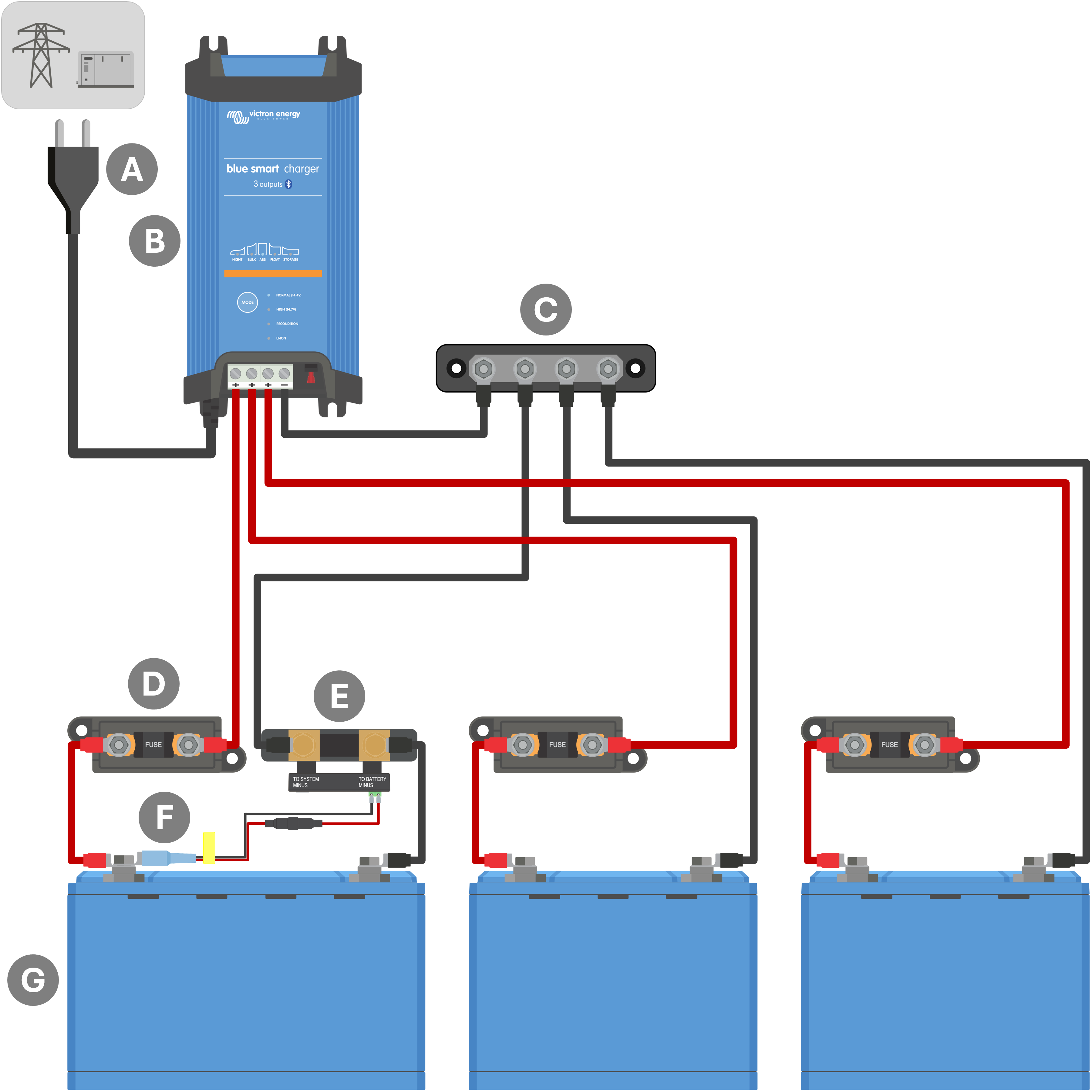
Key | Description |
|---|---|
A | AC power supply (mains power grid, generator or inverter) |
B | Blue Smart IP22 Charger (3 output model) |
C | DC negative busbar |
D | Fuses / circuit breakers x3 (locate as close as practical to batteries) |
E | SmartShunt or BMV battery monitor shunt (locate as close as practical to battery) |
F | Temperature and voltage sensor (Optional accessory, PN: ASS000100000) |
G | Batteries / battery banks x3 (any combination of 1, 2 or 3 batteries) |
Notice
A VE.Smart Network must be setup between the Blue Smart IP22 Charger and SmartShunt or BMV battery monitor to enable Bluetooth connectivity and communication between devices; refer to the 'Advanced Configuration > VE.Smart Networking’ section for more information.
5.3.4. System with multiple chargers
Refer to the wiring schematic below to connect multiple Blue Smart IP22 Chargers in parallel to a single battery / battery bank, with an optional SmartShunt or BMV battery monitor in the system:
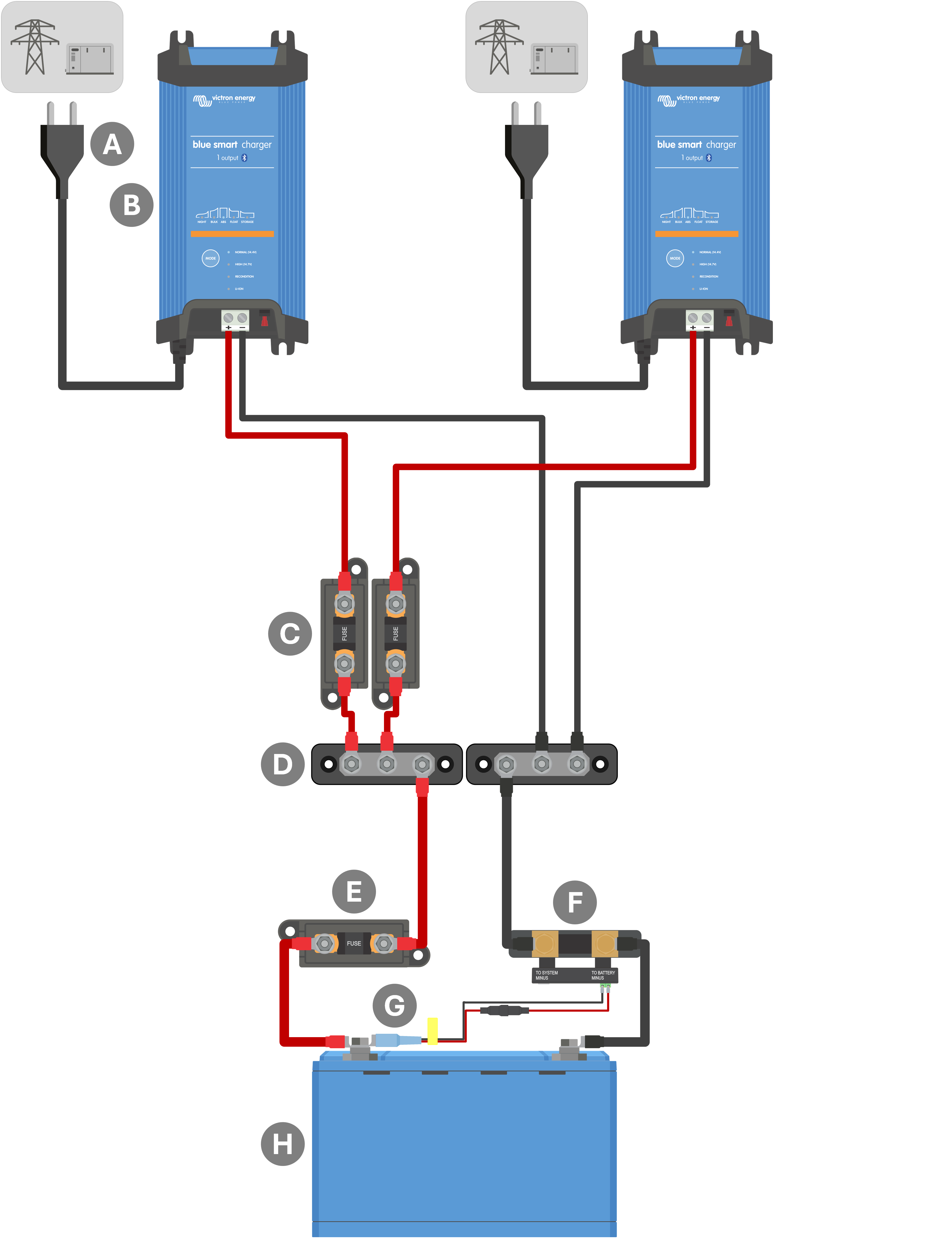
Key | Description |
|---|---|
A | AC power supply x2 (mains power grid, generator or inverter) |
B | Blue Smart IP22 Chargers x2 |
C | Fuses / circuit breakers x2 (locate as close as practical to DC positive busbar) |
D | DC positive and negative busbar |
E | Fuse / circuit breaker (locate as close as practical to battery) |
F | SmartShunt or BMV battery monitor shunt (SmartShunt/BMV is optional, locate as close as practical to battery) |
G | Temperature and voltage sensor (Optional accessory, PN: ASS000100000) |
H | Battery / battery bank |
Notice
A VE.Smart Network must be setup between all Blue Smart IP22 Chargers connected in parallel (and the optional SmartShunt or BMV battery monitor, if used) to enable Bluetooth connectivity and communication between devices; refer to the 'Advanced Configuration > VE.Smart Networking’ section for more information.