 Add this page to your book
  Remove this page from your book
  Manage book (
 Help
Help Table of Contents
VE.Bus Error Codes
General
During first installation, and in case of problems, update all devices to the latest firmware. This includes the latest VE.Bus firmware and also the latest firmware in the GX device.
Firmware update instructions:
To restart a system, first switch all units off, one by one. And then switch all units on again. Do this with the On / Off / Charger-only rocker-switch on the front of the device.
WARNING: The steps and instructions explained here, are intended to be carried to be carried out by trained professionals. AC (and also DC) Voltages can be lethal. And certain settings and firmware updates require experience and training as well.
Network cable quality
Make sure to use industrially made network cabling. Using self crimped RJ45 cables is a known cause of various of below list of errors.
This applies to network cables for split-, three phase and parallel systems as well as connecting a GX Device or other accessory on the VE.Bus network.
VE.Bus Error Codes
Error 1 - Device is switched off because one of the other phases in the system has switched off
One of the phases in a multi-phase system has failed. Commonly because of a Low battery, Overload or High temperature alarm. When this happens, the other phases will show VE.Bus Error Code 1.
Trouble shooting:
Diagnosing by LEDs Look for the failing phase, which will be the phase that is not showing VE.Bus Error Code 1. And check the LEDs on that phase to find out what the reason was for the shut down; which is typically Overload, Low battery or Temperature. The other units will indicate a VE.Bus error, indicating that they miss one unit.
Note that, due to the automatic restart, it is required to look at the LEDs while the issue is still present and the system is switched off.
Diagnosing on a GX Device The GX Device will indicate the VE.Bus Error #1 as well as the alarm status for each of the phases:
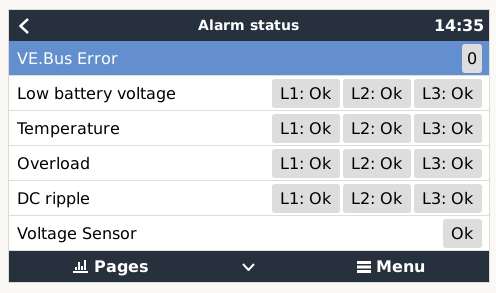
Note that, due to the automatic restart, it is required to look at the LEDs while the issue is still present and the system is switched off. Uploading the data to VRM will show a log; see GX manual, section VRM for details; both for systems with internet connection and systems without.
Diagnosing on VRM First make sure that Automatic alarm monitoring is enabled; that is necessary to create the Overload and Temperature errors in the log. You will see Overload and Temperature alarms occurring at the same time as VE.Bus Error 1.
Note for split- and three-phase systems: VRM as well as the GX device indicate on which phase there is an Overload, Low battery or Temperature alarm.
Recovery: auto-restart once the error is gone.
Error 2 - New and old type MK2 protocol mixed in the system
This should never happen, contact Victron service.
Recovery: auto-restart once the error is gone.
Error 3 - Not all, or more than, the expected devices were found in the system
Possible causes and solutions:
- This error often follows VE.Bus Error 1. Solution: solve the cause for VE.Bus Error 1. Note that when using an older CCGX (version before v1.40), it can be that the first error is not reported on the Alarm log on VRM. So even when it only lists VE.Bus Error 3, it can very well be that that error was preceeded by VE.Bus Error 1.
- The system is not properly configured: all VE.Bus devices connected to the VE.Bus network must be configured as one parallel, split- and/or three-phase system. Do not connect two separate VE.Bus systems together.
- Communication cable error: Check the communication cables. Make sure to use commercial patch leads and not hand-crimped cables - VE.Bus cabling is very sensitive to physical wiring faults.
- DC fuse blown of one or more units in the system: When mains is available all units seems to work correctly. But as soon as mains fails, or as soon as the system decides to switch to Island mode for any other reason, the units with the blown DC fuse will be without power and switched off - and thus be “missing” from the communication network.
- When switching off so called “complex systems” where the switch-as-group VE.Bus configuration is disabled and not all phases have AC-in. In some Multi models like the MultiPlus-II the VE.Bus communication remains active when switched off through Venus OS as long as AC in is available. In this case other Multis in the system with no AC input do not communicate. Causing the Multi with AC input to raise error 3. Complex systems are not supported and tested during Venus OS development.
Recovery: auto-restart once the error is gone.
Error 4 - No other device found
The master device is configured to run in a parallel-, split- and/or three-phase system, but cannot find other devices on the bus.
Multiple possible causes:
1. During a system restart
Error 4 can be seen temporarily while the system restarts after an error. Not a real error in that case, no need to investigate.
2. Because of issues in cabling
Faulty cables. Check the communication cables. Don't use self made cables.
Recovery: auto-restart once the error is gone.
Error 5 - Overvoltage on AC out
This problem can occur when the AC wiring of one of the slave units is not connected properly, or not connected at all.
Check the AC wiring.
Recovery: auto-restart once the error is gone.
Error 6 - Error in DDC Program
This means: error in an Assistant. To solve, follow these steps:
- update VE.Bus firmware in all devices to the latest firmware. Instructions here.
- download the latest VEConfigure and make sure it has downloaded all the latest Assistants.
- re-configure the system
This error can also occur in newer firmwares when a VE.Bus BMS is connected (or dis-connected) and the assistant is not configured accordingly.
Recovery: auto-restart once the error is gone.
Error 7 - External device connected, assistant required
An external device (e.g. a VE.Bus BMS) is connected but there is no Assistant loaded which handles that device.
Solution: configure the Multi/Quattro with a suitable Assistant.
Recovery: auto-restart once the error is gone.
Error 8 - Ground relay test failed
This error indicates a failed self-test of the MultiPlus-II or EasySolar-II internal1 ground relays.
During inverter operation, disconnected from mains, the ground relay is continuously tested to be closed. While switching over to mains it is tested to open. The ground relay tests are always performed: in systems with a grid code configured as well as system without a grid code configured. The only exception is systems where the relay is disabled in VEConfigure. See product manual for more information regarding the ground relay.
Using a GX device, the underlying detailed error can be seen for each individual inverter/charger in the system:
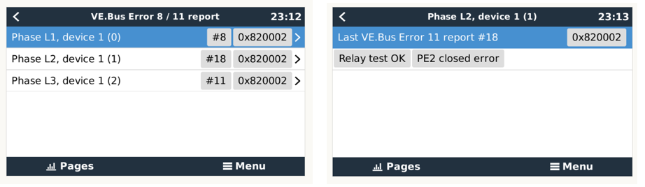
Definition of ground-relay related error types:
- GND Relay Error: Comes from the secondary controller; and can both mean that the relay is measured as being open, while it is expected to be closed, and the other way around.
- Error: PE2 Open: Comes from the main controller, means that the relay is measured as being open while expected to be closed.
- Error: PE2 Closed: Also comes from the main controller, and means that its measured as being closed while expected to be open.
Note that the pages as shown in above screenshots show the last error that happened in a unit. The errors are stored in non-volatile memory in the inverter/charger, and can therefore be something that was from a long time ago.
Therefore, take care to analyse only the latest error: make a note of the error counter (#8, #18, #11, and so forth in the first screenshot), and then switch the system on again. And after the next shutdown, compare the actual counters with the noted counters. Alternatively, use the Download feature on the Advanced page of the VRM Portal, and analyse the data in Excel.
Footnote 1: For the first revision hardware, the measurement also includes externally connected ground relays. For later revisions, it only checks the internal relay. See section below about the different hardware revisions.
Determining used hardware version
There has been a change (late 2020/early 2021) in the way the Ground relay test mechanism works. Newer units use an auxiliary contact on the ground relay, while older units measure the voltage between GND and Neutral.
The advantage of the new version is that the checking of the ground relay is immune to how the system is wired, and any possible errors in wiring on the input side and/or the output of the inverter/charger.
How to diagnose an error strongly depends on the underlying hardware, therefore as a first step, find out which hardware version is used, by using this table:
| Model | Serial number |
|---|---|
| MultiPlus-II 48V 3kVA | ≤ HQ2048 |
| MultiPlus-II 48V 3kVA GX | ≤ HQ2050 |
| MultiPlus-II 24V 3kVA | ≤ HQ2101 |
| MultiPlus-II 48V 5kVA | ≤ HQ2116 |
| MultiPlus-II 48V 5kVA GX | ≤ HQ2122 |
| EasySolar-II 48V 3kVA MPPT 250-70 GX | ≤ HQ2130 |
| All other models | Any serial number |
All non-listed models have the improvement from their first production, meaning they are always the new hardware.
Diagnosing GND relay errors in systems with new hardware:
Conclusion: if any of the units repeatedly displays a GND relay error, then that specific unit will have an issue with it's GND relay and should likely be replaced.
Diagnosing GND relay errors in systems with old hardware:
Note: With this type of hardware it is very well possible that the error is raised by unit X while the cause of the error can be in unit Y.
Possible cause #1: Neutral-out externally tied to GND
If the neutral-out is connected to GND externally then the unit will always detect that the GND relay fails to open.
Solution: Correct the wiring.
Possible cause #2: Neutral is bypassed intentionally
Neutral AC-in is connected to Neutral AC-out while not configured as such in the software.
The error will show up the moment the system tries to switch to grid and indicates either a wiring error, or a mismatch between the wiring and the configuration of the gridcode in the inverter/charger.
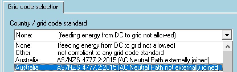
In case bypassing the Neutral is mandatory by local regulations, such as in certain regions in Australia, then select the corresponding “Neutral path externally joined” grid-code in the configuration software.
Otherwise, remove the bypass.
Possible cause #3: Leakage or short in the loads of the inverters
This could be either a defect in the wiring or a defect in one of the loads in the system.
- Check by first disconnecting all loads: open the circuit breakers.
- Restart system and check if it can switch to the grid without error.
- Then measure with a multi meter that there is no continuity between the neutral and the ground. (Alternatively disconnect all loads or sub-circuits, and bring them back online one by one. Just like when fault finding a shorted load that is tripping a circuit breaker.)
While testing this, be aware that:
- The test is performed by the units the moment the system attempts to switch to the grid. So checking this while only in inverting mode has no effect, since the ground relay is then closed; and a leakage or short in the system between AC-out neutral and ground will then not be detected.
- In case of a multiple units installed in parallel to each other, the AC outputs need to remain connected to each other: only disconnect the loads. Disconnecting all AC-out wires from each individual unit will not work, as doing so will result in a series of other errors.
Possible cause #4: Faulty ground relay, or its detection circuit
This is a hardware defect in the inverter/charger, or in at least one of the inverter/chargers in a system consisting of multiple units.
Since unit X can display the error while the root is in unit Y there is no easy way to find out. The most straight forward is to configure every multi as standalone and check whether it can switch to the grid without error.
Possible cause #5: Three phase systems only: loads mismatch with ground relay safety circuit
This will show either as a GND Relay Error or a PE2 Closed Error.
This issue affects three phase systems only.
For three phase systems (which have the old hardware!) and where all above steps have been checked carefully, contact your Victron dealer for next steps: in this case, all units will need to be replaced with the newer type.
Error 10 - System time synchronisation problem
This typically happens during a system restart, and is then not a real error; no need to investigate.
For example this screenshot from the GX device:
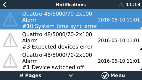
The real problem is Error 1. In this example it was caused by switching device L2 off with the front toggle switch. It was then quickly followed by Error 3. And when switching device L2 back on, briefly Error 10 is visible, followed by full recovery.
Note: System restarts can also be triggered when using Remote VEConfigure.
Other possibility: DC fuse blown of one or more units in the system. When mains is available all units seems to work correctly, but as soon as mains fails, the non powered units are disconnected from the system.
Recovery: auto-restart once the error is gone.
Error 11 - Relay Test Fault - Installation error or possibly relay failure
Error 11 indicates a failed automatic self-test of the MultiPlus-II or EasySolar-II relays. It is often a result of an installation or wiring issue, though it can also be triggered by a hardware failure (eg inoperable relays).
If a grid code is selected in VEConfigure, then the backfeed relays are tested every time before connecting to the mains.
Steps to take:
Step 1: Make sure that the units have been updated to the latest firmware version. There have been various VE.Bus error 11 related improvements in the firmware. This may correct the error, and if it does not, it will provide additional information to assist troubleshooting.
Step 2: Verify that system is properly wired to your installation and your local codes. Remember to check the earth connection on the unit AC input. Earth should be grounded according to your local grid rules. Do not connect Earth to Neutral in the unit itself. This will create a safety hazard and may prevent RCD devices from working. Contact another licensed electrician if in doubt.
Step 3: Disconnect the L and N wiring from the ACout terminals on each inverter/charger. Which, in case of a parallel or three phase system, isolates the ACout connections for each unit. If the system then starts normally there might be a problem with a connected load (e.g. a leakage between load, neutral and ground).
Step 4: Check your Neutral-out connection. In most cases there should be no external connection between ACin-Neutral to ACout-Neutral, or to Earth.
In Australia, using grid code AS4777.2:2015, it may be mandatory to make an external connection between Neutral-in and Neutral-out. Select either design configuration in the grid code section while programming the MultiPlus-II with firmware 466 or above.
After configuration, always confirm that the system is safe with routine electrical safety checks in both modes (eg test RCD operation with AC input connected and disconnected).
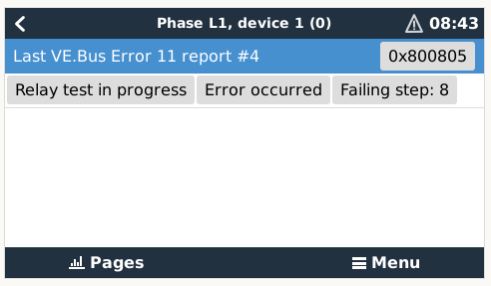
Step 5: Neutral and line input might be inverted. Check the input connections, swap them if needed and retry. In this case, “Failing step: 8” will show.
Detailed diagnosis of Error 11
After updating your VE.Bus inverter/charger to firmware 454 or higher; and running Venus OS v2.23 or later, a detailed VE.Bus Error 11 report is available in the GX device menu, under MultiPlus → Alarm Status → VE.Bus Error 11 report.
Examples of information in the GX Device menus:
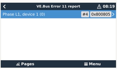
The information shown is:
- A six digit number; which contains all the details
- An error ID (#4 in above screenshot). Note that this does not count the number of VE.Bus errors; its just a unique ID that can help recognizing that a new error has occurred.
- Flags
- The failed step; it counts backwards: step 9 → 8 → 7 and so forth.
Common causes:
- Failing step #8: check that line and neutral have not been swapped. Unlike non-grid code installations; line and neutral need to be wired correctly.
- AC0/AC1 mismatch and UMains error: this is fixed in VE.Bus inverter/charger firmware version 455.
Other shown error details, listed below, are not related to any known installation issue and can be caused by a faulty unit or configuration issue. In any case, also when one of below errors shows, make sure to go through all the above steps for any error 11 issue.
- Failing steps #2-7.
- AC0 /AC1 mismatch.
- Communication error.
- UMains mismatch.
- Period Time mismatch.
- Drive of BF relay mismatch.
Unable to solve?
When the error persists after the all above steps, or when any other Failed step or extra explanation shows, then the unit may be faulty. Follow the support procedure and contact your dealer. Make sure to document full system wiring in a diagram, all steps and tests taken to diagnose and rule out installation error, and provide a photo of the error details shown on the GX Device menu.
Recovery: auto-restart once the error is gone.
Error 12 - Config mismatch with 2nd mcu
Some Multi models (e.g. MultiPlus-II) have two microcontrollers.
Certain configuration settings, as done with VEConfigure, have to be stored in both microcontrollers. In very rare situations it can happen that the stored configurations do not match and that the mismatch cannot be handled automatically. In this case error E12 will be generated.
To solve this error, connect the device to VEConfigure 3, verify/correct the settings and press 'Send Settings'.
Make sure to select the option 'all settings' instead of 'modified settings'.
Recovery: auto-restart once the error is gone.
Error 14 - Device cannot transmit data
Most probably a short circuit in the communication cables.
Another possibility, very rare though, is a broken component on the board. Return the device to the nearest service point for repair.
Recovery: auto-restart once the error is gone.
Error 15 - VE.Bus combination error
A combination error of VE.Bus products, firmware versions or commands has occurred
This error can occur for example when:
- An Interface-1140 with old firmware is combined with a new Multi firmware
- When external BMS commands are send while a VE.Bus BMS is connected
- The connected VE.Bus product firmware versions are incompatible. (This can in most cases be solved by updating the firmware.)
Recovery: auto-restart once the error is gone.
Error 16 - VE.Bus dongle is missing
Update firmware to latest version: VE.Bus dongles are no longer necessary.
Instructions here.
Recovery: system remains off until restarted.
Error 17 - Phase master missing
Error 17 shows on slaves (only). The slaves in a system will report this error when the communication with the phase-master has timed out.
This error can only occur on systems with multiple devices installed per phase. For example a single phase installation with two or more devices in parallel, or a three-phase installation with six or more devices.
Steps to take:
- In some cases this error can be seen temporarily while using Remote VEConfigure to write a new configuration.
Solution: ignore the error; the system will recover by itself. - The most likely cause is a cable-related communication issue on the VE.Bus network:
Solution: First check the network cables sockets. If that doesn't solve it, replace all network cables, including the cable to the GX Device. Make sure to also inspect the female RJ-45 sockets, instead of only the cabling: sometimes badly mounted RJ45 cable connectors prevent the spring-contacts in the female RJ45 connectors on the Multis to properly make contact. Make sure to machine-made cabling. Do not use self-crimped cables. - DC fuse blown. In this case, all units can in some situations seem fine and work well as long as mains is available. And then when there is no longer AC available on the input (mains fails or generator is stopped) the non powered units are disconnected from the system.
Solution: Check the fuse in all units; replace the broken one. - Update firmware and Assistants of the inverter/chargers. And of the GX Device.
Solution: (1) Update the Inverter/charger firmware - (2) Update the Assistants - (3) Update the GX Device firmware.
Systems with multiple slaves per phase
Error 17 can show on one or more slaves in a phase (visible by looking at the LEDs, not on VRM or GX Device). If the slaves can still communicate with each other; then the error will only show on one slave: all slaves that can see on the network that another slave is already showing Error 17 will not show the error as well.
Unable to solve it?
If after all above steps you are still experiencing a VE.Bus Error 17, contact your dealer whom will contact Victron repairs; please provide photos of the installation and network cabling. Depending on the situation, they might advice to replace the GX device and the inverter/chargers. We advise to first replace cables, and if that doesn't help then thereafter only the GX device at first, since that is less work than replacing the inverter/chargers.
Recovery: auto-restart once the error is gone.
Error 18 - AC Over-voltage on the output of a slave while switched off
Solution: check if AC wires are not swapped by accident. There can never be voltage on the AC out when a unit is switched off.
Recovery: system remains off until restarted.
Error 19 - Slave does not have AC input!
Common cause - System is configured with multiple synchronised inverter/chargers but AC input (e.g. from a generator) is only connected to one of the Inverter/Chargers.
Solution: Either connect the AC input to all units, or change the configuration of the synchronised units in VE.Bus System Configurator (note not VEConfigure), and disable the 'Switch as Group' Function. This setting will allow only a single Inverter/Charger to charge without error. Note this setting is not adjustable in an ESS system.
Recovery: system remains off until restarted.
Error 20 - Configuration mismatch
Extended VE.Bus options are not allowed when a gridcode is selected.
Recovery: system remains off until restarted.
Error 22 - This device cannot function as a slave
This device is an obsolete and unsuitable model. It should be replaced.
Recovery: system remains off until restarted.
Error 24 - Switch-over system protection initiated
This error indicates that one or more units report feeding back a significant current through its back-feed relay, while those relay are supposed to be open, and -obviously- no current can flow through an open circuit.
What is the back-feed relay? It is the relay that closes when connecting to the grid or generator. And which opens when there is no power available, ie when the system is in island- or invert-mode.
Error 24 is raised when a Multi or Quattro detects current flowing through the back-feed relay during a period when the relay should be open. This can mean one of three things:
- The relay did not open.
- The related current measurement circuit is faulty.
- A multiplus II is used with an external current sensor connected, but the option 'External current sensor connected' is not checked in ve.configure.
Error 24 is a very rare error. Possible causes in order of probability:
- (only on MP II models when using external sensor) the option 'External current sensor connected' is not checked in ve.configure.
- There is too much AC load connected at the moment the relay needs to switch off. This large current will prevent the relay contacts from opening.
Solution: remove excessive load. See transfer switch capacity in the datasheet for the maximum rating. - The AC input voltage slowly drops before it is being rejected by the Multis. Typically happens in installations with a generator. Especially when combined with AC loads that increase their current draw when the AC voltage drops: by the time that the inverter/charger initiates the disconnect, the current through the relays has increased well beyond the ratings, and is too high to open them.
Solution: Make the Multis or Quattros disconnect earlier: increase lower limit of AC input voltage in VEConfigure3. For example to 210 VAC. The factory setting is 180 VAC. - The back-feed relay has a hardware failure
Solution: Replace faulty unit. - The related current measurement circuit is faulty.
Solution: Replace faulty unit.
Diagnosing a parallel, multi or split-phase system?
Error 24 will always appear on all units at the same time. There is unfortunately no indication, not on LEDs, nor on a GX device, VRM, or any other manner, to see which of the devices caused the error. Below procedures outlines how to manually determine which unit has a faulty relay.
Do make sure to first, always double check option 1 and 2 in above list. Those are the common causes. In case that doesn't lead to a solution, follow this procedure to find out if its a relay issue, and then which unit.
Execute this procedure right after the error occurred; do not first reset the system.
Step 1
Start with making a video of all units and their LED code. Do not first reset the system; and do not reset it after making the video either.
Step 2
Completely disconnect all AC wiring, both in- and out, on all units. Make pictures of the terminals; to make sure when discussing this with an engineer; there is no misunderstanding on what has been meant by this instruction.
Step 3 Now, with an ohm-meter, measure the resistance between the neutral terminals on AC-input and the AC-output, A working unit will show no connection between these terminals. And also measure the resistance between the Line terminals of AC-input and AC-output.
A faulty unit will measure zero or close to zero resistance.
Good units will measure discontinuity between the Line in and out terminals. And measure a few hundred ohms between the neutral In and Out AC terminals.
Recovery: system remains off until restarted.
Error 25 - Firmware incompatibility
Make sure to use the same firmware in all devices.
Solution: update all devices to the latest available firmware. Instructions here.
Recovery: system remains off until restarted.
Error 26 - Internal error
Should not occur. Switch all equipment off, and then on again; it will then resume operation. Contact Victron Energy if the problem persists.
Recovery: system remains off until restarted.
Error 30 and 31 - Ghost errors
Both these are non-listed VE.Bus errors. They are caused by a corrupted message on the VE.Bus. There may be an issue with the RJ45 UTP cable(s) or their connections. To try to resolve it, make the changes suggested in the “Troubleshooting VE.Bus Network interference” guide.
Error 128 - Connect prevented by failing relay test
Relay test that keeps failing for more than 5 minutes,
If a grid code is selected in VEConfigure, on a Quattro-II the backfeed relays are tested every time before connecting to the mains. This test is repeated continuously until the test passes. Error 128 indicates that the relay test keeps failing for more than 5 minutes, and the Quattro-II there for cannot connect to grid.