 Add this page to your book
  Remove this page from your book
  Manage book (
 Help
Help This is an old revision of the document!
Table of Contents
Hub-4 / grid parallel - manual
Note: make sure to always update all components to the latest software when making a new installation.
Introduction
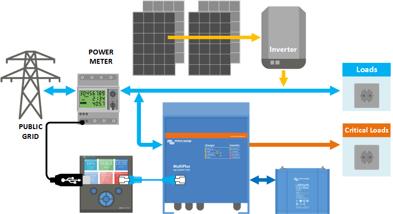
Hub-4 is a Grid-parallel Energy Storage system, using the Multi or Quattro bidirectional inverter/charger as its main component. It optimizes self-consumption: at times when there is excess PV power, the PV energy is stored in the battery. And that stored energy is then to power the loads at times when there is a shortage of PV power.
The system is managed by the Color Control GX (CCGX), which also provides extensive monitoring, both locally and remotely via our VRM Portal and the VRM App. The VRM app is available for both iOS and Android.
Schematic overview
Features
- Grid parallel energy storage system that optimizes self consumption.
- Wide range of available inverter/chargers: 800 VA to 10.000 VA in 12, 24 and 48 VDC.
- Flexible:
- a single phase inverter/charger installation in a single-phase system
- a single phase inverter/charger installation in a multi-phase system
- a split- or three-phase inverter/charger system in a multi-phase system
- Both wired and a wireless connection to the meter central distribution box is possible.
- (optional) No-break UPS output.
- (optional) Phase compensation.
- Built-in anti-islanding / loss of mains detection. Currently certified for limited number of countries/models, more certification coming.
- No restrictions on PV Array size.
- No minimum or maximum battery size.
- Suitable for many battery types.
- Three operating modes, from basic to custom, covering both standard and custom systems.
- Free usage of the VRM Portal and the VRM App for remote monitoring.
- Winter switch: keep batteries charged in periods where there is a continuous shortage of solar power
Operating modes
- Standard
The system runs automatically, and uses excess energy harvested during the day to fill the gaps when there is not enough PV power available. Typically in the evening and night. Easy configuration in Assistants and on the Color Control GX. - Advanced
Same as standard, but more flexibility is given to implement time shifting, load management or other energy management optimization algorithms. Either by ModbusTCP commands or by running additional self implemented code on the Color Control GX. Often the best of both worlds: complete flexibility and benefit from the VRM Portal and all other functionality already available on the CCGX, without having to add additional cost of extra PLCs or other control modules. more information. - Custom
Customer self implements their control loop and grid measurements, and uses the MultiPlus and/or Quattros as simple, remote controllable, bidirectional inverter/chargers that can be set to either charge or discharge an x amount of Watts. for more information.
1. Required parts
| Part no. | Description |
|---|---|
| PMP, CMP or QUA | Multi or Quattro inverter/charger (see Note 1 below) |
| REL200100000 | Wired AC sensor - 1 and 3-phase - max 65A per phase |
| BPP000300100R | Color Control GX |
| ASS03006xxxx | RJ-45 UTP Cable |
| BATxxxxxx | Batteries. (Victron) Lithium batteries are recommended due to their long life |
| ENS Anti-islanding options, choose one of below options: | |
| No external needed | For certain countries, our Multis and Quattros have built-in certified anti-islanding protection. |
| RCD000100200 | Anti-islanding box 63A single phase - UK (includes the UFR1001E) |
| RCD000300200 | Anti-islanding box 63A single and three phase (includes the UFR1001E) |
| REL100100000 | Ziehl anti-islanding relay UFD1001E (Many countries) more info |
| REL100200000 | Ziehl anti-islanding relay SPI1021 (Italy) |
| Grid sensor connection option A: wireless connection between the CCGX and the AC sensor | |
| ASS300400100 | Zigbee to RS485 converter (AC Power adapter and 30cm wire to AC sensor is included) |
| ASS300400200 | Zigbee to USB converter (USB cable is included, connects to the CCGX) |
| Grid sensor connection option B: wired connection between the CCGX and the AC sensor | |
| ASS030570018 | RS485 to USB interface 1.8m |
| ASS030570050 | RS485 to USB interface 5m |
Notes:
- The Multi or Quattro used needs to be a recent type with the new microprocessor (26xxxxx or 27xxxxx). All units currently shipping have this new microprocessor. Also, the Multi or Quattro needs to run the latest 4xx firmware. Contact your Victron representative for the firmware files. Update instructions are here.
- The RS485 to USB interface cable from the CCGX to the AC sensor can be extended up to 100 meters max.
- The REL200100000 is the EM24DINAV93XISX from Carlo Gavazzi. Other EM24 models from Carlo Gavazzi can also be used, as the communication is the same. For example the EM24DINAV53DISX, which uses Current Transformers and can therefore work in systems > 63A per phase. Note that this model is not stocked by Victron Energy, we recommend to purchase it locally.
2. Battery, inverter/charger and PV dimensioning
Battery size
There are several factors to take into account when dimensioning the battery:
- Small batteries will be more cost effective: all available storage capacity is used every day
- Small batteries will be charged and discharged with high currents: especially with lead batteries this will reduce battery life time
- Larger batteries, combined with a relatively large PV installation, can store excess power during good days, which can then be used during several consecutive days of bad weather
- Larger batteries provide longer autonomy during a power outage, requires using the UPS output
Inverter/charger size
Because it is installed parallel to the grid and the loads, the inverter size can be reduced to (much) smaller than the max expected nominal and peak load.
For example, to cover the base load of a two person house hold, the MultiPlus xx/800 might already be sufficient. For a household with one family, the MultiPlus xx/3000 can already manage nearly all appliances, when not more than one of them is running at the same time. This means a MultiPlus xx/3000 can already reduce the power consumption during late spring, summer days and early autumn with sufficient storage to (nearly) zero.
PV Array and PV inverter size
In a Hub-4 installation, the PV Inverters are connected in parallel to the inverter/charger. Because of this, the size of the PV array and the PV inverter is not limited by the maximum nominal power of the inverter/charger. This is in contrast to other AC-Coupled installations, such as Hub-2, where the Factor 1.0 rule applies.
3. Single vs multi phase installations
3.1 Single phase inverter/charger system
Phase compensation
Phase compensation, for a single phase inverter/charger installation, part of a multi phase system.
Phase compensation, which is common practice in Germany, is used to have a storage hub connected to only one phase, and compensate on that phase for the other two phases, thereby effectively regulating the total power of all three phases combined.
See the following example, where the Hub is connected to L1, and by compensating for phase L2 and L3 as well, it regulates the total power at the distribution panel to 0 W.
| L1 | L2 | L3 | Total | |
|---|---|---|---|---|
| Load | 100 W | 400 W | 200 W | 700 W |
| Inverter/charger | -700 W | 0 W | 0 W | -700 W |
| Distribution box | -600 W | 400 W | 200 W | 0 W |
Enabling or disabling phase compensation is done in the Hub-4 settings on the Color Control GX. See the screenshot further down below in this manual.
3.2 Split- and three-phase inverter/charger system
Installation details
- The Multis need to be configured as a three-phase system. Use VE.Bus Quick Configure or VE.Bus System Configurator for this.
- Update all Multis to firmware 405 or newer
- Install the Hub4 Assistant in all units: all the phase-masters but also all slaves (if any)
- Three phase loads: it is possible to connect three-phase loads to the AC out of the Multis, also called the UPS-output in a Hub-4 system. Those loads will be powered from the battery during a power failure.
Power regulation details - phase compensation setting
In a three-phase Hub-4 system, there is at least one Multi installed on each phase. We recommend leaving phase-compensation setting to its default: enabled. The system will regulate the total power of the three phases to zero. When phase-compensation is disabled, each separate phase is regulated to 0.
With phase-compensation enabled, all the inverter/chargers will either be charging or discharging: the system prevents to charge the battery on one phase, and discharge it on the other phase.
When the system as a whole produces power (PV power exceeds consumption), the Multis on the phases with a net power production will be set to charge the battery. Multis on phases with a net power usage, Ppv < Pload, will be on idle.
When the system as a whole consumes power (Consumption exceeds PV production), the Multis on the phases with a net power usage will discharge the battery to compensate for the shortage. Multis on phases with a net power production will be on idle.
Disabling phase compensation
In a hub-4 system it is still possible to balance the grid power of each phase to 0W. Disable phase compensation. This would however cause significant losses, because power will flow from one phase to another through the DC connections. Causing losses when converting from AC to DC on one phase and then from DC to AC and the other phase.
Phase compensation, balancing the total grid power to 0 is therefore more efficient. It avoids the AC-DC roundtrip losses.
Note on the maximum charge current
In a multi-phase system, the charge current is configured per phase. There is not a total charge current which the system adheres too. This means that, for example when there is a relatively small battery bank, and a huge over production of PV on L1, and not on the other phases, only part of that over production on L1 will be used to charge the battery.
4. Connecting and configuring the AC sensor
A Hub-4 setup requires an AC sensor connected in the main distribution panel: between the grid and installation. This AC sensor has been designed for 3 phase measurement, but can be configured for single phase support as well.
3-phase setup diagram:

single phase setup diagram:

Note the jumper between terminals 1 and 4.
Meter configuration
Change the front selector of the AC sensor so it is not in the locked state. This will allow the CCGX to automatically configure the meter. The front selector is located next to the display as indicated in the image below.

Option A: Wireless connection to CCGX
1. Connect the Zigbee to USB converter to the CCGX using the supplied USB cable. A few seconds after connecting, the active LED should be on and the TX/RX LED should be blinking (the converter takes its power from the CCGX, so the CCGX needs to be switched on as well).

2. Connect the Zigbee to RS485 converter to the EM24 energy meter:
| Converter | Grid meter |
|---|---|
| GND | Terminal 43 |
| A | Terminal 42 |
| B | Terminal 41 |


3. Make sure only one Zigbee device is powered up right now: the Zigbee to USB converter connected to the CCGX. Power down all others. If you don't do this, the Zigbee to RS485 converter may be connected permanently to another Zigbee device.
4. Connect the 12V DC power supply to the Zigbee to RS485 converter. When the power is switched on, check the LEDs again.
Option B: Wired connection to CCGX
Connect the meter to the CCGX using the USB to RS485 converter cable:
| RS485 Converter | Grid meter |
|---|---|
| Yellow | Terminal 41 |
| Orange | Terminal 42 |
| Black | Terminal 43 |
The Red, Green and Brown wire are not used

5. Multi/Quattro installation and configuration
First, follow the instructions as per the standard installation manual. AC Input 1 is connected to the distribution panel of the installation. And, optionally, AC Output 1 can be used as a UPS output: in the event of a grid failure, the built-in inverter will power loads connected to AC Output 1.
Then use VEConfigure3 to load the assistant 'self consumption Hub-4' into the device.
If you have a Multi Compact, check the DIP switches: DIP switch 1 must be on, and DIP switch 2 must be off.
If you used an earlier (beta) version of the assistant, make sure to remove it from the 'private assistant directory' in VE configure, or disable the directory. You can set the private directory in the 'Assistant Tools' tab within the 'Assistants' tab.
6. Battery charging and discharging behavior
(Note: All absolute voltages mentioned in the text below are for a 12V system and should be multiplied by 2 or 4 for a 24V or 48V system.)
- When there is less PV power available than needed by the loads (a PV shortage), energy stored in the battery will be used to power the loads until the battery is considered empty. There are three parameters that check if the Battery is empty:
- Battery State of Charge. Minimum state of charge is configured in the Hub-4 Assistant.
- Battery Voltage. See Dynamic Cut-off section below.
- Low cell signal from BMS
- When the battery is empty, the Sustain mode is activated. See Sustain section below.
- Whenever there is excess PV, the battery will be charged. Charge current and other parameters are configured on the Charger tab in VEConfigure3.
- The Hub-4 Assistant will disable PowerAssist. Please keep this option disabled.
- Make sure to keep the lithium batteries checkbox on the charger page consistent with the battery choice in the Assistant.
Sustain Mode
The purpose of the Sustain Mode is to prevent battery damage caused by leaving batteries in a deeply discharged state. The Sustain Mode is entered as soon as the battery is discharged, see above.
During Sustain Mode, the batteries will slowly be charged from the grid; maximum charge current is 5 Ampére. The Sustain level is 12.5V for lithium batteries. For non-lithium batteries, the sustain level is 11.5 V for the first 24 hours, and after that it is raised to 12.5 V.
Excess solar power will also be used to charge the batteries. Sustain stops as soon as there has been sufficient excess solar power available to raise the battery voltage 0.1 V above the sustain level. Normal operation will then continue: solar deficits are complemented with power from the battery again.
Dynamic Cut-off
Note: dynamic cut-off is useful for batteries with a high internal resistance. For example OPzV and OPzS. Less relevant for LiFePO4 batteries, see graph.
With Dynamic Cut-off, the dc-low-disconnect level is a function of the battery current drawn from the battery. When a high current is being drawn from the battery, a lower DC cut-off voltage threshold is being used, for example 10 V. And similarly, when the battery is only being discharged slowly, a high DC cut-off voltage is used, for example 11.5 V.
This way, voltage drop caused by battery internal resistance is being compensated for, and battery voltage can reliably be used to stop discharging when the battery is discharged.
The picture below shows the default 'Discharge' vs. 'DC input low shut-down voltage' curve for the different battery types. The curve can be adjusted in the assistant.

7. Color Control GX configuration
- Power up the system.
- After a few seconds, the display will come to life. If not, check the wiring of the system.
- Within 60 seconds after power up, the CCGX will detect the meter. The meter will show up in the device list on the display. When selected, the CCGX will show a page with current measurements.
- Select 'Settings' from the device list and select 'Wired AC Sensors'. This will show the list of known AC sensors. In this case there will be a single entry.
- Select the entry. A new page will show up with the settings of the AC sensor.
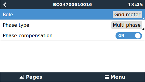
- Make sure 'Role' is set to 'Grid meter', and 'Phase Type' matches your setup (i.e. single or multi phase).
- For further configuration, see the Color Control GX manual.


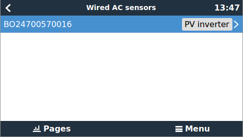
8. Using the Wired HUB-4 AC Sensor to measure PV Inverter output
Instead of used for the Hub-4 regulation, the same three phase meter can be configured to measure output of a PV Inverter. Make sure to check Paragraph 1.3 in the Color Control GX Manual for other options of measuring PV Inverter output.
Installation is similar to the AC sensor on the grid. Terminals 1, 4 and 7 should face the PV inverter. On the CCGX change the 'Role' of the meter to 'PV inverter'. You can now also chose its 'Position'. In the case of a Hub4 setup, this must be 'Input 1'. If you want to connect a single phase PV inverter to a 3-phase system connect all 3 phases to the grid phasing terminals (3, 6 and 9). Now you can chose on which phase you want the PV inverter by connecting the L1 line of the PV inverter to terminal 1, 4 or 7.
There are 3 options to connect the extra AC sensor:
- Wired connection with an extra RS485 to USB converter cable. Works just like the grid meter.
- Wired connection with modbus multidrop (both AC sensors connected to the same RS485 to USB converter cable). In this case you need to change the modbus address of one of the AC sensors (see below).
- Wireless connection: the AC sensor is connected to an additional Zigbee to RS485 converter just like the grid meter. Also requires change of the modbus address.
Changing the modbus address:
- Press the joystick down until until the display shows 'Pass'. The joystick on the right side on the display, above the front selector).
- Press the joystick down again and release immediately.
- Press the joystick right several times until 'Address' appears. Press the joystick down. Now you can adjust the address by pressing the joystick up and down. Set it to 2.
- Press down again. 'Baudrate' appears.
- Press down again twice. 'Address' appears again.
- Press right until 'End' appears.
- Press down. The display now shows measurements again.
On a single phase setup, you can use a single AC sensor to measure both grid and PV inverter. For wiring see the diagram below.

On the CCGX go to the grid meter in the Wired AC sensor settings. Make sure 'Phase type' is set to 'Single phase' and 'PV inverter on phase 2' is enabled.

9. FAQ
What happens when the Multi does not receive data from the CCGX / Wired AC Sensor?
It will switch to Bypass, and Sustain mode is still active and will prevent the battery from being discharged below, approximately, 50%. See Paragraph 6 for the details on Sustain and the Sustain Voltages.
Is there a winter mode, like in Hub-2?
Yes.
VEConfigure keeps giving the warning 'Device must be reset'
This message is a bug. There is no need to reset the device. This erroneous indication is solved in firmware version xxyy403.
I get a lot of Low battery pre-alarm warnings ?
Solved by updating to xxyy403 or higher.
Does Hub-4 work for parallel systems?
Yes, Hub-4 works for systems where multiple Multis or Quattros are installed on the same phase and configured to operate in parallel.
DISQUS
~~DISQUS~~