 Add this page to your book
  Remove this page from your book
  Manage book (
 Help
Help This is an old revision of the document!
Table of Contents
CCGX & Fronius PV Inverters
By connecting a Fronius PV Inverter and Color Control GX (CCGX) together you will be able to:
- See Fronius information on the CCGX.
- Monitor the Fronius on the VRM Portal.
- Allow the Victron system to control the Fronius output power, Zero feed-in. See the ESS manual, chapter 2.1.3 Fronius Zero feed-in for details.
This document describes how to setup the monitoring functions. For more information on using Fronius PV Inverters in a Victron system, see: AC-coupled PV with Fronius PV Inverters.
1. Requirements
| Model | Required accessory |
|---|---|
| Fronius Symo Light | Purchase and install the datamanager 2.0 |
| Fronius Symo | No accessory needed, datamanager card installed from factory |
| Fronius Galvo | No accessory needed, datamanager card installed from factory |
| Fronius Primo | No accessory needed, datamanager card installed from factory |
| Fronius IG Plus (*) | Purchase and install the datamanager 2.0 |
| Fronius Agilo | Purchase and install the datamanager box |
(*) The Fronius Zero feed-in feature - which is part of an Energy Storage System ESS - will work on all the above models except the IG Plus.
All recent Fronius inverters - for example the Fronius Primo - will arrive fitted with a datamanager 2.0, as standard.
Both the Fronius and the CCGX need to be connected on the same LAN - either via Wi-Fi or Ethernet.
Note that the Datalogger Web is not supported. Contact your Fronius dealer to find out about the upgrading options.
2. Configuring
2.1 Setup Local Area Network (LAN) Configuration
In order to establish a data communication between the Fronius and the CCGX, you will have to setup a valid LAN IP address on the Fronius, using one of the following methods. If you are in doubt, which method is the best for your network, please ask your system administrator or IT support.
2.1.1 DHCP addressing method
If you have a DHCP server running on the LAN the Fronius and CCGX are connected to, you don't need to manually configure your LAN IP addresses as the DHCP server does this for you. Make sure, that the “IP Switch” is in “B” (default) position on the datamanager, to allow the Fronius to obtain it's IP address. It can be reviewed in the Address Lease Table of the DHCP server.
2.1.2 Link-local addressing method
When no DHCP server is present on the LAN and you only have one Fronius unit to connect, Link-local addressing can be used to establish data communication between the CCGX and the Fronius. This could be the case, if you use a WiFi Network for the CCGX to gain access to the Internet and have a Fronius connected to the wired LAN Interface of that CCGX.
Note, that no direct access to the internet will be possible for the Fronius in that configuration and therefore only communication to the CCGX is possible.
This method can only be used to configure a single Fronius unit within a LAN. Multiple Fronius devices in the same LAN must be configured with DHCP, or manual addressing method.
- Make sure the “IP Switch” on the Fronius Datamanager is on position “A”
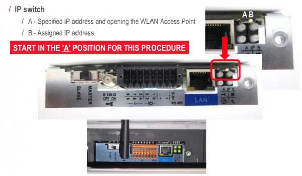
- Connect both, the Fronius and the CCGX, on the same LAN network, either directly with a LAN cable or using a network switch.
- The Fronius is now accessible and having a “Link-local” capable IP address configured: 169.254.0.180

2.1.3 manual addressing method
You will have to configure the IP address of the Fronius to be in the same subnet as the IP address of the CCGX. To do this, first have a look at the IP configuration your CCGX is using on that network.
The IP configuration can be reviewed in Settings –> Ethernet. The important settings are the IP address and Subnet Mask.
If the LAN IP address and Subnet Mask of the CCGX is not configured yet, you will have to set it first.
As an example, the IP address on the CCGX could be: 192.168.10.1 and the Subnet Mask: 255.255.255.0.
Configuring the Fronius to the same subnet means setting a manual IP address to: 192.168.10.2 and the same Subnet Mask of 255.255.255.0 on the Fronius.
Every device on your LAN has to have a unique (different) IP address and so the last segment (.1/.2) in this example has to differ on every device on the same LAN. The highest value, that can be set for this segment is 254.
The subnet is described by the first 3 segments in this case and so they have to be the same. Configuring multiple devices with exactly the same IP addresses will lead to network errors. Use different IP subnets for the WiFi and wired LAN interface. The IP address ranges used on each interface should differ in the third segment.
As an example: 192.168.10.1-254 for LAN IP's and 192.168.11.1-254 for WiFi IP's.
Configure the Fronius Datamanager to use an IP address on the same subnet, as described above. You may need to refer to the Fronius operating manual for how this is done for your Fronius Inverter model,
If you would like to connect the Fronius to be able to use the internet connection of your Local network, you have to set Gateway and DNS IP addresses on the Fronius as well. They should be exactly the same as in the Settings –> Ethernet of the CCGX.
2.2 Adding Fronius to the CCGX
1. In the CCGX, navigate to Settings and then the Fronius PV Inverters section. You will see this menu:
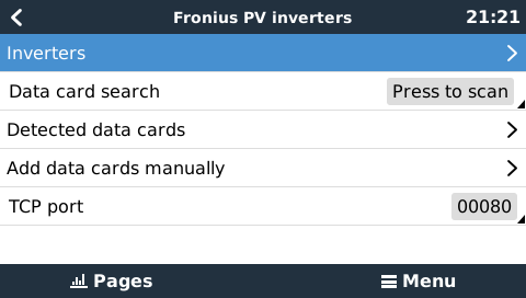
2. Select Scan in the CCGX menu, and after completion go into the Inverters submenu to see the results. If scanning does not find the inverter, manually add the IP address of the Fronius Datamanager from its card, or box.
3. Once located, you will see the Inverters listed in the menu. The name used will be the serial number of the inverter - which you will also find on the inverter itself:
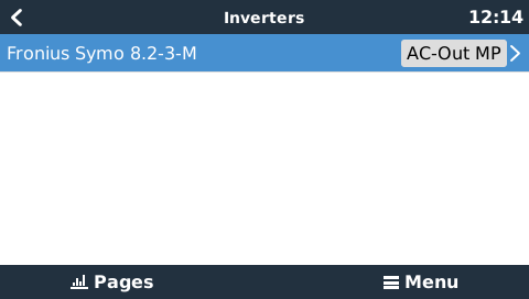
4. Configure the position relative to the Multi or Quattro (is it: AC Input / AC Output); and the phase for each inverter in the list:

- Position: = the position relative to the Multi or Quattro [AC Input 1 / AC Input 2 / AC Output]
- Phase: = the phase on which the PV Inverter installed. Disabled and set to Multi-phase for split- and three-phase PV Inverters
- Show: = show this device in the system or not. Use this feature when there are multiple, separate, energy systems on the same LAN.
5. Done!
2.3 Device scan details
As mentioned above the CCGX should find all Fronius inverters automatically. It will scan all IP-addresses in the local network (that is, all IP-addresses within the netmask assigned to the CCGX) to check whether or not they are Fronius datamanager cards. This scan will be performed during CCGX startup; whenever the CCGX loses connection to a data card; and a scan can also be initiated manually by selecting 'Press to scan'.
Usually a scan is completed within a minute - though if you have a large subnet it may take much more time. If you don't want to wait for completion, enter an IP-address manually.
All data cards found will be entered in the 'Detected data cards' list. The CCGX will regularly (once every minute) scan the IP-addresses in this list in order to find new data cards, or reconnect to data cards whenever the connection was lost.
If you changed to TCP port number on the data manager, you should change this setting on the CCGX, too (TCP port) - otherwise leave the setting at its default (80).
3. Monitoring CCGX
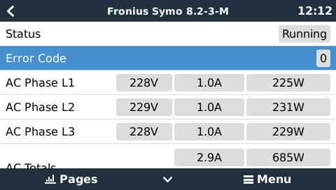
When the Fronius is detected and configured on the CCGX all PV inverters will be visible in the devicelist.
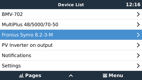
To see the device details, navigate to the menu.
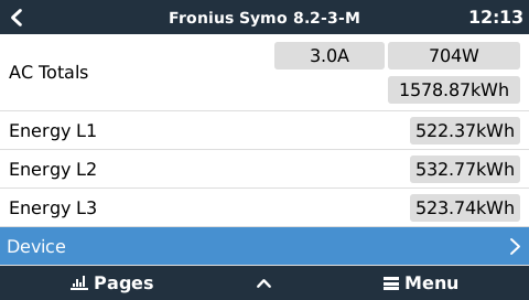
Here you can see the current state, current power generated, total power generated.
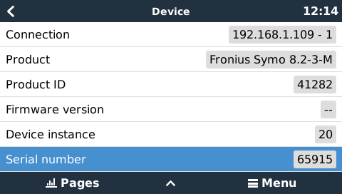
For more details on each device navigate to the Device menu. Here you will find: IP address, Product name, product ID, and Serial number, etc.
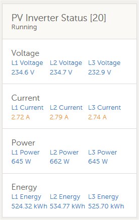
4. Monitoring on the VRM Portal
To see the yield on the VRM site (in the Advanced tab), don't forget to enable the PV Inverter yield widget(s) in Settings → Advanced tab setup.
DISQUS
~~DISQUS~~