 Add this page to your book
  Remove this page from your book
  Manage book (
 Help
Help Table of Contents
Victron & SOLARMD Battery
The combination of Victron products with SolarMD Battery lithium batteries has been tested and certified by the Solar MD R&D department. This combination has extensive field experience and is actively supported by Solar MD.
The SolarMD Battery includes an integrated Battery Management System (BMS) with each battery module and a LOGGER V2 that interfaces with the Victron GX device and supports multiple battery modules. To find out how to install the Logger V2 watch this YouTube installation video.
Supported models
| Model | SS4037 | SS4074 | SS202 | SS4143 | SS3143 |
|---|---|---|---|---|---|
| Battery |  |  |  |  | 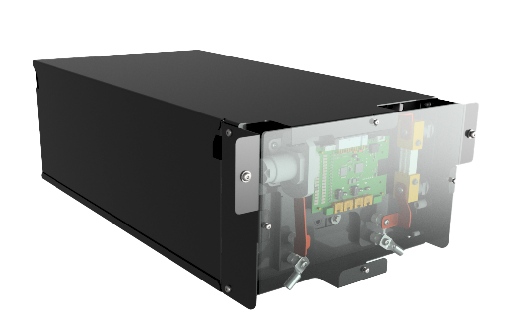 |
| ESS | yes | yes | yes | yes | yes |
| Grid Backup | yes | yes | yes | yes | yes |
| Off-Grid | yes | yes | yes | yes | yes |
| Module capacity | 3.7kWh | 7,4kWh | 7,4kWh | 14.3kWh | 14.3kWh |
| Module limit | 256 | 256 | 256 | 256 | 256 |
| Max capacity | 947 kWh | 1894,4 kWh | 1894,4 kWh | 3660.8 kWh | |
| Logger V2 | yes | yes | yes |
For SS237 - 25.6V (24V systems) please contact Solar MD support team for further assistance.
== System overview ==
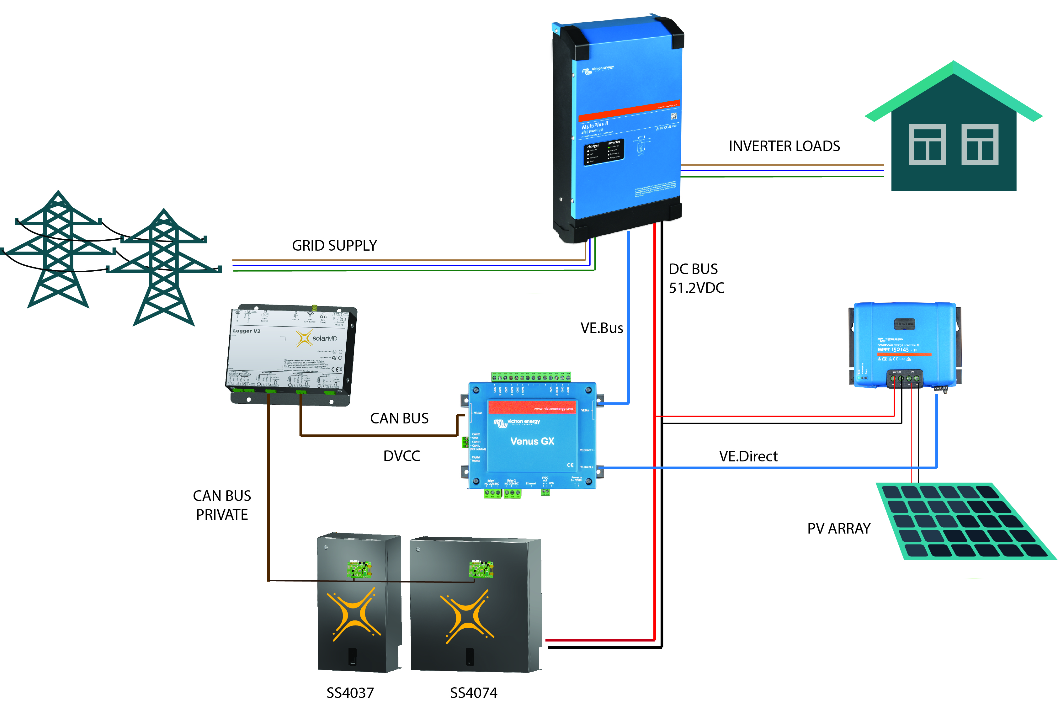
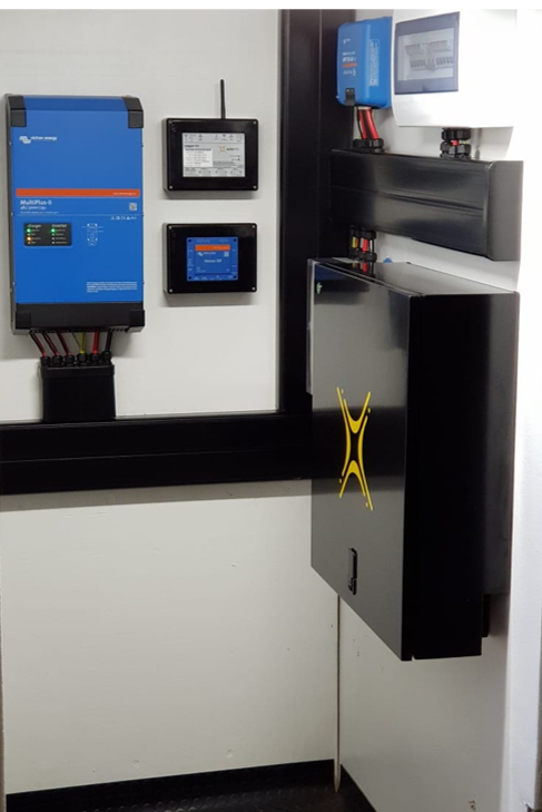
== Typical installation with a Single SS4074 and Multiplus II 48/3000 ==
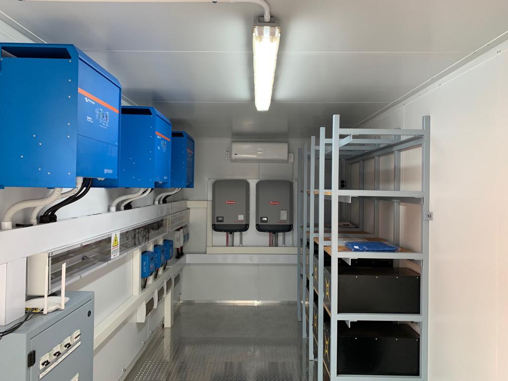
== Typical installation with Multiple SS202 modules, 3 Quattros, 3 MPPTs, and Fronius integration ==
1. Product & System compatibility
1.1 Off-grid, Backup, and Energy Storage Systems are possible
Victron + SolarMD Battery can be used for the following system types:
- Energy Storage Systems - Self Consumption (ESS - Start page)
- Grid Backup
- Off-grid
1.2 A GX device is required, eg Color Control GX (CCGX), Venus GX (VGX), etc
It is essential to use the CAN-bus connection of a GX device with the SOLARMD batteries for the keep-alive signal, communication of charge and discharge limits, error codes and state of charge. When used with Solar MD batteries, the minimum required firmware version for the GX device is v 2.15. Please use the latest firmware version on all connected devices, including CCGX/VGX, Inverter/Charger, and MPPTs. There are regular updates to improve performance and reliability.
1.3 All 48V Multis, MultiPlusses, MultiGrids and Quattros are compatible for SS074/SS4037/SS202
The minimum firmware version is 422. Though updating to the latest firmware is recommended where possible. These inverter/charger units must be connected to the GX device via the VE. Bus connection port. In grid-connected systems, advanced control functions are configurable in the ESS settings on the GX device. In off-grid systems, the control functions of the SOLARMD Battery Management System (BMS) are built into the latest version of the GX device.
1.4 All 48V BlueSolar and SmartSolar MPPT Chargers are compatible
For proper operation, the Battery battery needs to be able to control the charge current of the solar MPPTs. It is recommended to use the MPPTs with VE. Direct port with SOLARMD batteries. MPPTs with a VE.Direct port MPPTs are controlled via the GX device. Make sure the GX device runs v2.15 or later, and the MPPTs to 1.39 or the latest available version. The MPPT requires connection to the GX device to regulate charge currents as the batteries require (due to temperature, etc) To test operation, try disconnecting the GX device from the MPPT. After a time-out, the MPPT will stop charging and flash an error code on its LEDs. The error code is error #67: no BMS. MPPTs with a VE.Can port Firmware should be at least version 2.05. When using VE.Can MPPT's, it is recommended to use the Venus GX (VGX), instead of the CCGX. The VGX has two CAN-bus interfaces available and allows communication between the MPPTs, SOLARMD and the VGX.
1.5 Battery compatibility
The following batteries are supported for the 48V systems:
| SolarMD BATTERY LV series type 51.2V |
|---|
| BATTERY SS4037 |
| BATTERY SS4074 |
| BATTERY SS202 |
For SS237 - 25.6V (24V systems) please contact Solar MD support team for further assistance.
Solar MD also releases a firmware update for the LOGGER V2 and BMS. LOGGER V2 Firmware versions earlier than V6-13 are not compatible with Victron equipment and can cause the battery to not be detected. All software updates of Solar MD equipment are done remotely and automatically as soon as the Logger V2 has an internet connection.
Minimum Solar MD firmware version: LOGGER V2 6.13_15-Mar-2017.
This version can be seen on the Solar MD monitoring platform.
Batteries BMS_PL with older firmware versions can be updated with BMS_EM hardware. Please contact SOLARMD for more information.
2. Minimum Battery Sizing
The following information is provided by Solar MD, it is reproduced here for your convenience and should always be confirmed with the latest Solar MD manuals and specifications.
Each battery module is 72Ah (SS4037) or 144Ah (SS4074) at 48V (51.2V nominal).
The following charge rates are managed automatically by the SolarMD LOGGER V2 and GX device. Temperature effects on charge rates should be considered in the design stage in extreme hot and cold climates.
Using very large solar arrays with battery banks that are too small can exceed the limits of the batteries ability to charge and possibly lead to the LOGGER V2 triggering over-current alarms.
The table below shows the minimum number of battery modules required for the specified inverter/charger configuration:
Battery Modules Required – per 3.7kWh (SS4037)
| Phases | Single Phase | Three Phase | Single Phase | Three Phase |
| Inverter/Charger | Self-consumption | Self-consumption | Off-grid | Off-grid |
| Multiplus 48/3000/35 | 1 | 3 | 1 | 3 |
| Multiplus 48/5000/70 | 1 | 3 | 2 | 6 |
| Quattro 48/5000/70-100/100 | 1 | 3 | 2 | 6 |
| Quattro 48/8000/110-100/100 | 2 | 4 | 2 | 6 |
| Quattro 48/10000/140- 100/100 | 2 | 5 | 3 | 9 |
| Quattro 48/15000/200- 100/100 | 3 | 6 | 4 | 9 |
| EasySolar 48/3000/35-50 MPPT150/70 | 1 | 3 | 1 | 3 |
| EasySolar 48/5000/70-100 MPPT150/100 | 1 | 3 | 1 | 6 |
Battery Modules Required – per 7.4kWh (SS202 / SS4074))
| Phases | Single Phase | Three Phase | Single Phase | Three Phase |
| Inverter/Charger | Self-consumption | Self-consumption | Off-grid | Off-grid |
| Multiplus 48/3000/35 | 1 | 3 | 1 | 3 |
| Multiplus 48/5000/70 | 1 | 3 | 2 | 6 |
| Quattro 48/5000/70-100/100 | 1 | 3 | 2 | 6 |
| Quattro 48/8000/110-100/100 | 2 | 4 | 2 | 6 |
| Quattro 48/10000/140- 100/100 | 2 | 5 | 3 | 9 |
| Quattro 48/15000/200- 100/100 | 3 | 6 | 4 | 9 |
| EasySolar 48/3000/35-50 MPPT150/70 | 1 | 3 | 1 | 3 |
| EasySolar 48/5000/70-100 MPPT150/100 | 1 | 3 | 1 | 6 |
Battery Modules Required – per 14.3kWh (SS4143))
| Phases | Single Phase | Three Phase | Single Phase | Three Phase |
| Inverter/Charger | Self-consumption | Self-consumption | Off-grid | Off-grid |
| Multiplus 48/3000/35 | 1 | 1 | 1 | 2 |
| Multiplus 48/5000/70 | 1 | 2 | 1 | 3 |
| Quattro 48/5000/70-100/100 | 1 | 2 | 1 | 3 |
| Quattro 48/8000/110-100/100 | 1 | 3 | 2 | 4 |
| Quattro 48/10000/140- 100/100 | 1 | 3 | 3 | 4 |
| Quattro 48/15000/200- 100/100 | 2 | 5 | 3 | 6 |
| EasySolar 48/3000/35-50 MPPT150/70 | 1 | 1 | 1 | 2 |
| EasySolar 48/5000/70-100 MPPT150/100 | 1 | 2 | 1 | 3 |
3. CAN Bus Wiring
Use any UTP cable. Plug 3 of the wires (PIN 7, PIN 8, PIN 3) into the SolarMD LoggerV2. Plug the other side with RJ45 connector into the GX device.
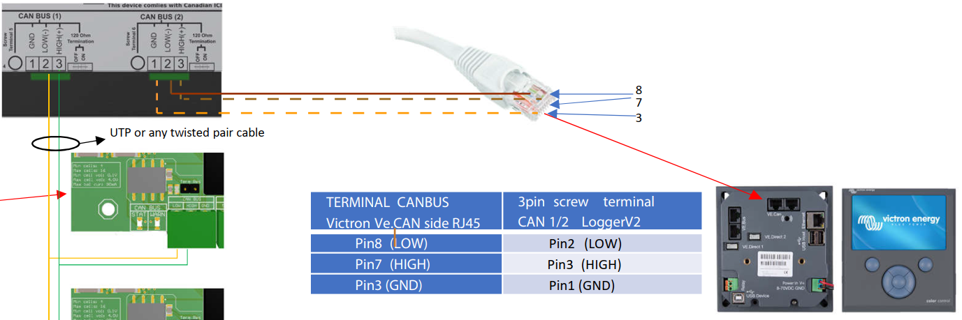
Then, plug a VE.Can terminator in the other VE.Can socket on the GX device alternatively, you can use the termination on the Logger V2 side. Two VE.Can terminators are included with the package of the GX device as an accessory, only one is used. Keep the other one as a spare.
More information about the cable can be found in its manual.
Without properly connecting this cable, the battery will not show up on the display of the GX device.
It is important to ensure this connection and display of the battery on the GX device display before attempting firmware updates or settings changes on other devices if they depend on the power supply from the battery. It is the LOGGER V2 that signals the battery modules to shut down if the signal from the GX device has not been received.
4. VEConfigure settings
This section presumes familiarity with VEConfigure software.
4.1 General tab
- Check the “Enable battery monitor” function
- Set the battery capacity to the total capacity of the battery: eg 72Ah times the number of battery modules for the 3.7 model.
- The other parameters (“State of charge when bulk finished” and “Charge efficiency”) can be left to their default setting: They are ignored for SolarMD battery installation.
4.2 Charge parameters
In normal operation, the charge parameters are controlled by the SOLARMD LOGGER V2 and communicated through the system by the GX device to the inverter/charger and MPPT. However, as a precaution, it is advised to set these as suggested below.
Charger tab
| VEConfigure Charge Parameter | Setting |
|---|---|
| Battery type | Lithium |
| Charge curve | Fixed |
| Absorption voltage | 54.6 V |
| Float voltage | 53.4 V |
| Absorption time | 1 Hr |
Note: make sure to double-check the float voltage after completing Assistants, and if necessary, set it back to 53.4 V.
4.3 Inverter Settings
In the Inverter tab of VEConfigure
| VEConfigure Inverter Parameter | Setting |
|---|---|
| DC input low shut-down | 47V |
| DC input low restart | 51V |
| DC input low pre-alarm* | 51V |
* The pre-alarm setting is dependent on your preference and on site-specific requirements. You may wish for this to be activated earlier (eg 51V) in an off-grid situation to allow time to start a backup generator. If the system is configured in ESS mode, you may not wish to have this alarm trigger until below the Sustain threshold voltage (eg 50V), as this system is in no danger normally and will 'sustain' at 51V without needing to trigger an alarm.
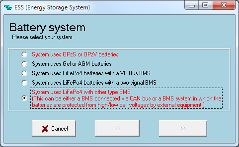
ESS System Settings
If you are using the battery as part of a grid connected ESS system, please review the ESS Quickstart guide and Design and Installation Manual.
The settings that are specific to the SolarMD battery in the VEConfigure ESS Assistant are below:
Select the externally managed Lithium battery option
| ESS Parameter | Settings |
|---|---|
| Sustain voltage. | 50V |
| Dynamic cut-off values | set all values to 49V. |
| Restart offset: | 1.2 V (Default) |
5. GX device and LoggerV2 Configuration
On the GX device, go to Settings, System setup:
| Venus Settings → System Setup Parameter | Value |
|---|---|
| DVCC | ON |
| Shared Voltage Sense | OFF |
| Shared Temperature Sense | OFF |
If you have a VE.Can MPPT, it is advised to use the Venus GX in place of the CCGX.
- Select the CAN-bus BMS (500 kbit/s) CAN-profile in the CCGX.
Menu path:
Settings → Services → CAN-profile.

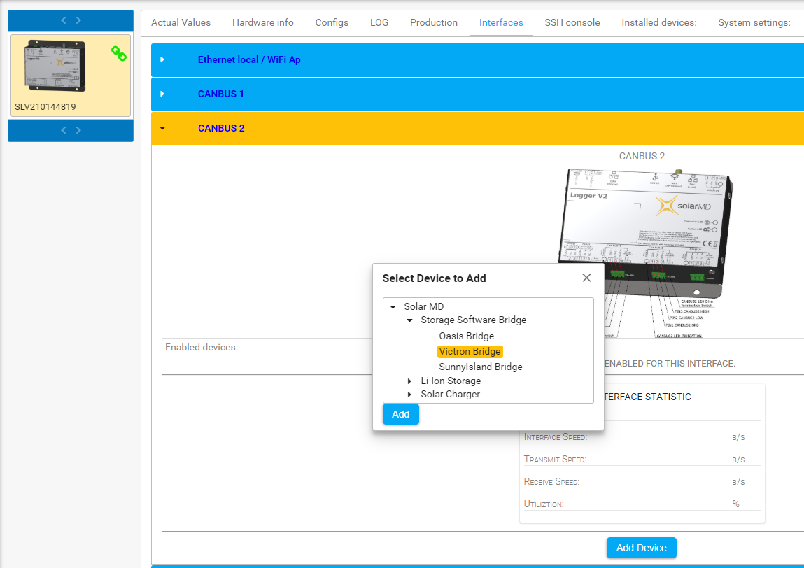
- On the Solar MD portal (http://login.mypower24.co.za) Select Victron Bridge on CAN2:
Menu path:
My Devices → Logger → Interfaces → CANBUS2. After choosing Victron Bridge, proceed with Software reboot on the Logger V2 in the Tab “System Settings”
- After properly wiring and setting up, the Battery will be visible as a battery in the device list:
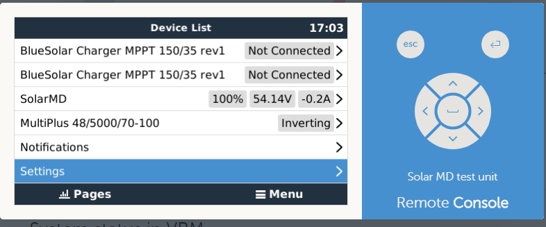
(if you have multiple batteries a single entry will show up, which represents all batteries).
- The parameters option within the battery page shows the actual battery charge and discharge limits
This parameters page is also a good place to check that all batteries are connected and working properly. In normal working conditions, for the SS4037 (3.7 model), the current limit is 100A per module. For example, 140A charge current limit (400 / 100 = 4) means there are 4 SOLARMD battery Batteries connected.
Color Control GX Configuration
The CCGX only has one available VE.Can port. It is not possible to connect both CAN products such as VE.Can MPPT (250 kbit/s) and a Battery battery CAN-bus (500 kbit/s) together on the CCGX. As the SolarMD Logger V2 MUST be connected, you will need to use the port for that. This will mean no data is collected from the VE.Can MPPT, nor can the CCGX control it. This means you are required to use the “Allow to Charge” wire configuration for the MPPT. “Allow to Charge” on the Logger V2 can be set via the 2 provided Relays.
Venus GX Configuration
The VGX has two CAN-bus interfaces available. The VE.Can MPPT remain connected to the VE.Can port, while the SOLARMD CAN-bus cable should use the specific CAN-bus connections (H, L, GND). This allows data from the MPPT and SOLARMD battery simultaneously. You will only need to connect the Allow-to-charge wires if using the VE.Can MPPT and VGX.
The CAN-bus connections are galvanically isolated at the SOLARMD LOGGER V2. There are no issues using the non-isolated connection of the VGX.
6. VE-Direct MPPT Settings
In normal operation, the MPPT charge characteristics are governed by the GX device connected to the SolarMD battery.
This section presumes familiarity with VictronConnect.
The settings below are a precautionary measure.
| MPPT Parameter | Setting |
|---|---|
| Battery voltage. | 48V |
| Absorption voltage | 54.6V |
7. NEW Direct communication via BMS EX
7.1 Communication Cable Connection
It is recommended that CAT5e cable be used. The termination resistor on the last battery should be ON, the rest should be OFF. Please use between all batteries CAN2 and CAN1 straight cable connection. For the last battery to the GX device Type B cable connection is required.
The minimum firmware version of the BMS EX should be v 178

7.2 A Battery settings
Refer to the BMS of LoggerV manual to configure the CANBUS 2 interface for a Victron device. Note: After changing CANBUS 2 settings on the battery, the Victron GX device will need to be rebooted.