2. Installation
2.1. What's in the box
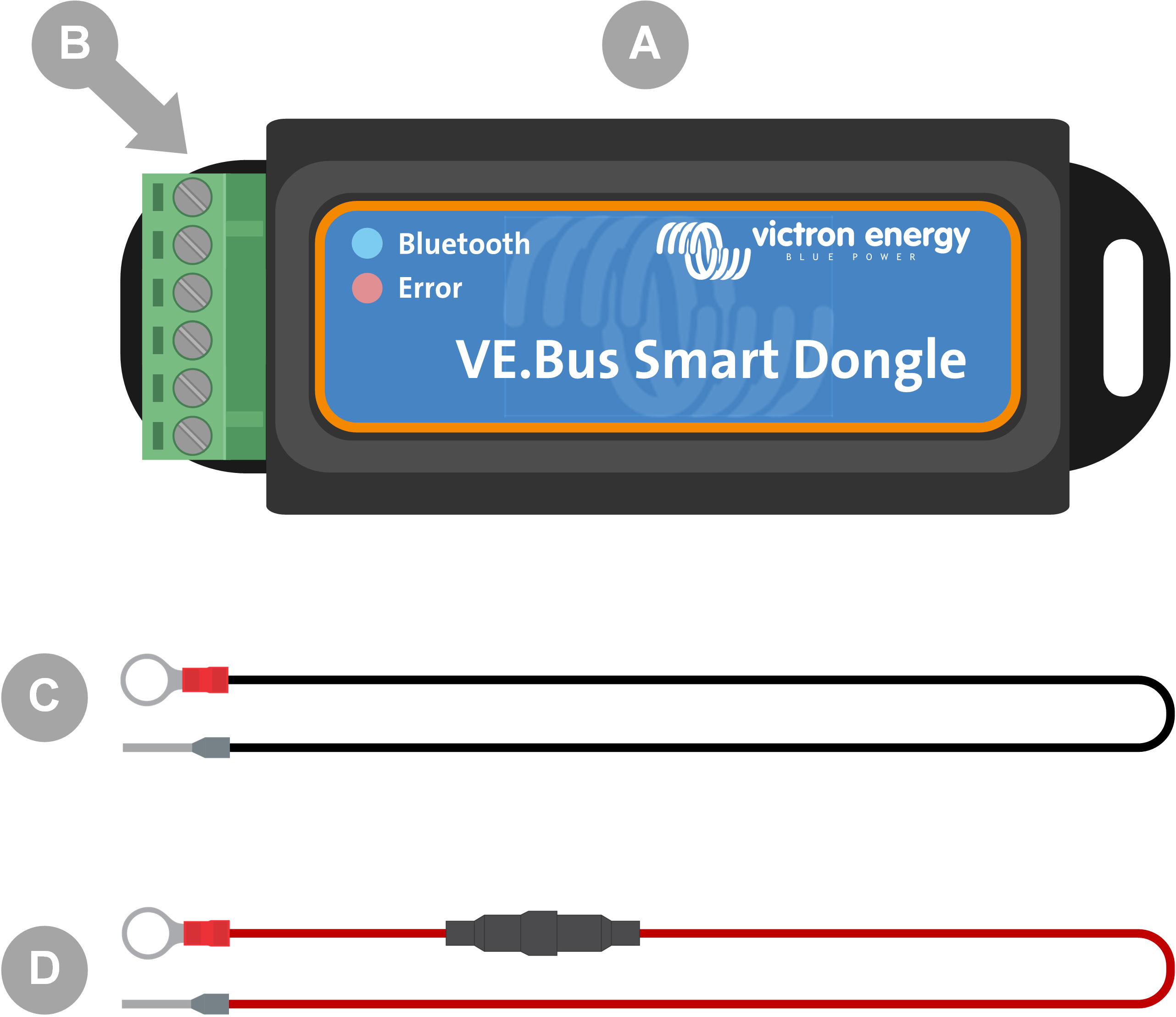
VE.Bus Smart Dongle.
Removable terminal block with screw terminals.
Black battery (-) connection wire with 10mm eye terminal.
Red battery (+) connection wire with 10mm eye terminal and inline fuse.
What's not in the box
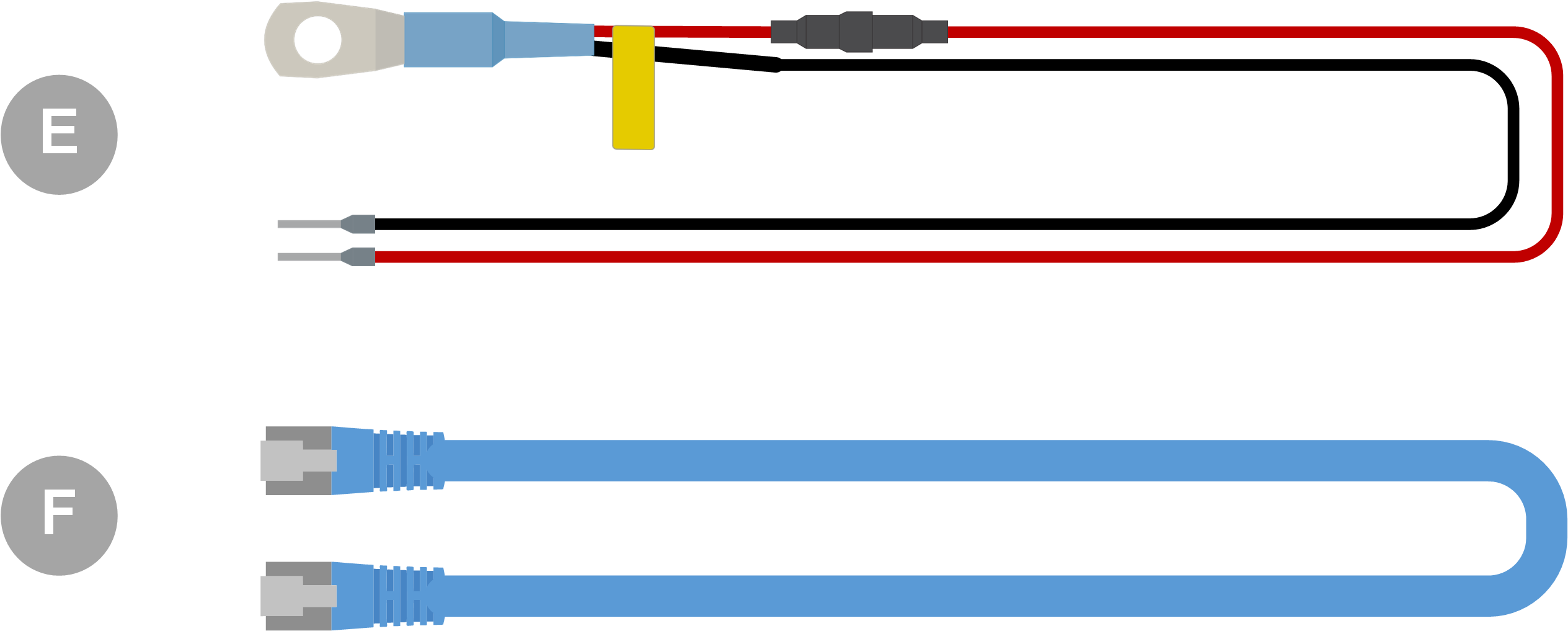
Temperature sensor for BMV-712 Smart and BMV-702. This temperature sensor can be used as an optional external temperature sensor. Note that the temperature sensor is shipped with the label “CAUTION: BMV702 only!”. This caution can be ignored for use with the VE.Bus Smart dongle.
UTP RJ45 cable. This cable is required to connect the VE.Bus Smart Dongle to the inverter/charger or inverter. This cable needs to be purchased separately.
2.2. Installation without external battery sensor
This is the default installation method, whereby the dongle's internal temperature sensor is used.
Remove the connection terminal block from the dongle.
Connect the red power wire to the B+ terminal of the terminal block.
Connect the black power wire to the B- terminal of the terminal block.
Connect the eye terminal of the black power wire to the negative terminal of the battery.
Connect the eye terminal of the red power wire to the positive terminal of the battery.
For battery temperature sensing, mount the dongle on top or on the side of the battery, using the dongle's adhesive mounting. If battery temperature sensing is not required, the dongle can be mounted near the battery using adhesive mounting or screws.
Plug the terminal block into the dongle.
Connect the dongle RJ45 terminal to the inverter/charger RJ45 terminal using an RJ45 UTP cable.
|
|

2.3. Installation with an external battery sensor
This is an optional installation method, whereby an external temperature sensor is used instead of the dongle's internal temperature sensor.
This installation requires the Temperature sensor for BMV-712 Smart and BMV-702. Note that this temperature sensor is a different temperature sensor than the one that is included with the inverter/charger. It needs to be purchased separately.
Note that the red power wire included with the dongle is not used in this installation. The red power wire will be replaced by the red wire of the temperature sensor.
Remove the connection terminal block from the dongle.
Connect the temperature sensor red wire to the B+ terminal of the terminal block.
Connect the temperature sensor black wire to the T- terminal of the terminal block.
Connect the black power wire to the B- terminal of the terminal block.
Connect the eye terminal of the black power wire to the negative terminal of the battery.
Connect the temperature sensor eye terminal to the positive terminal of the battery.
Mount the dongle on the battery using the dongle's adhesive mounting, or mount it near the battery using screws or the adhesive mounting.
Plug the terminal block into the dongle.
Connect the dongle RJ45 terminal to the inverter/charger RJ45 terminal using an RJ45 UTP cable.
 |
|
2.4. Updating firmware
Before using the dongle, ensure that its firmware, the inverter/charger firmware and the VictronConnect app version are all up to date.
Update the inverter/charger to the most recent firmware version. Note that this needs to be at least firmware version xxxx415 or higher (or version xxxx419 or higher for full functionality).
Make sure you are using the most recent version of the VictronConnect app.
Update the firmware version of the dongle. Do this by connecting to it using the VictronConnect app. On the first connection, the VictronConnect app will likely indicate that the firmware needs to be updated. To update the dongle, follow the prompts by the VictronConnect app.
To perform a manual firmware update or to check if the dongle has the most up-to-date firmware, go to the product settings page via the cog symbol
 in the top right-hand corner and then click on the 3-dot symbol
  in the top right-hand corner of the setting page and select "product info".
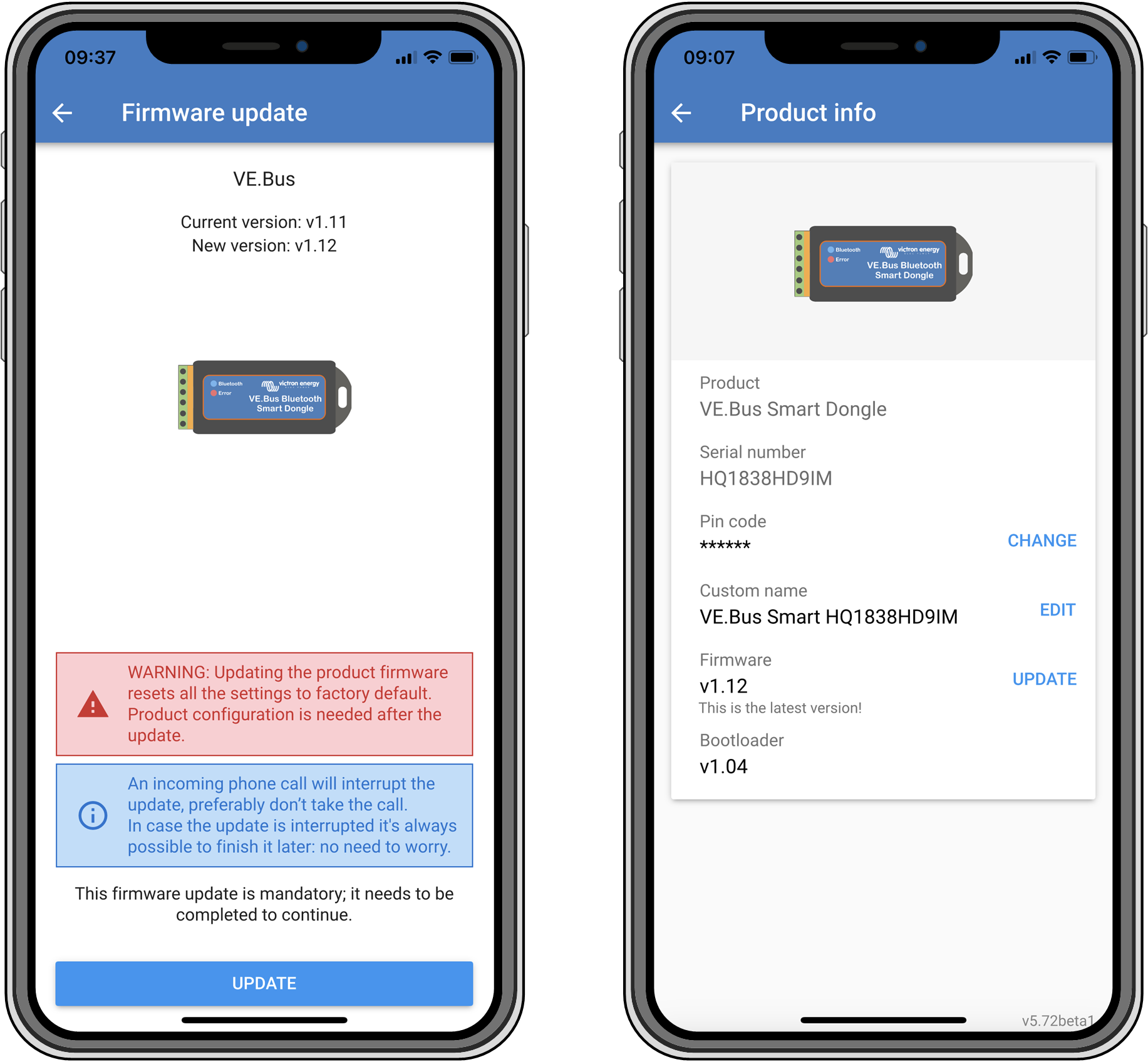 |
VictronConnect firmware update and product info screens.
2.5. VE.Smart Networking
The dongle supports VE.Smart Networking. When the dongle is part of VE.Smart Networking it can transmit battery temperature and battery voltage data to the network.
To add or set up VE.Smart Networking, navigate to the VictronConnect dongle settings page by clicking the cog symbol in the top right-hand corner. On the settings page select "VE.Smart Networking". You have two choices: create a new network or join an existing one.
When the dongle is part of VE.Smart Networking, this is indicated by a  symbol on the dongle VictronConnect overview page. See the orange circle in the image below on the right. When clicking on the symbol, you can check if the dongle is transmitting to the network and what type of data it is transmitting.
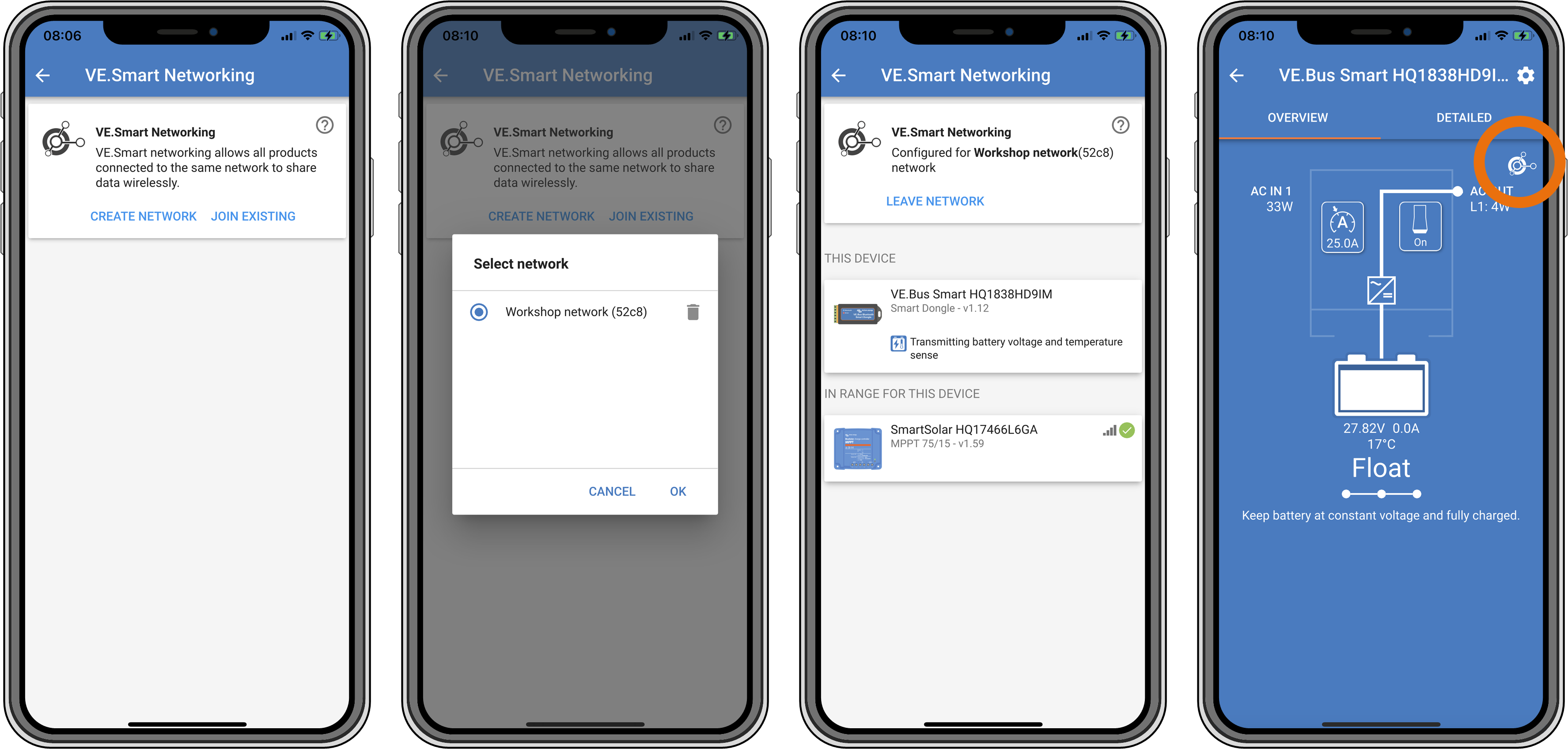
VictronConnect VE.Smart networking screens.
Note
For more information on VE.Smart Networking also see the VE.Smart Networking manual.