3. Installation
3.1. Mounting
Mount on a non-flammable surface. The orientation is not critical.
Ensure that the clearance between the mounting surface and the fan inlet is not obstructed. Mount on a flat surface to maintain proper airflow.
For optimum performance, a minimum of 10cm space should be kept free around the product for cooling. With limited cooling, e.g. due to insufficient ventilation, the charging current will be reduced sooner than at the specified maximum ambient temperature.
With limited cooling or extreme ambient temperature, the charger can become hot (especially the bottom plate). Due to internal temperature control, the heat sink will never get warmer than 90 °C; this is no problem for the charger. Make sure that the mounting surface can withstand this temperature.
Mount close to the battery but never directly above the battery (to prevent damage from gassing of the battery).
3.2. Cable type recommendations
For correct connection of a cable to the input/output screw terminals, stranded wires with flexible cores can be used according to:
IEC 60228 - Class 2 (stranded), Class 5 (flexible)
UL486A-B - Class B/C (stranded), Class I (flexible)
Cables with twisted cores are very stiff, which means that they are rarely used in practice. The table below provides an overview of how to recognise the different wire classes.
Single wire diameter in the bundle | ||
|---|---|---|
Nominal cross-section | Class 5 (IEC) | Class I (UL) |
10mm2 / 8AWG (8,4mm2) | 0,4mm | 24AWG |
16mm2 / 6AWG (13,3mm2) | 0,4mm | 24AWG |
25mm2 / 4AWG (21,1mm2) | 0,4mm | 24 AWG |
3.3. Using ferrules
The use of ferrules is not mandatory. However, they can simplify installation by bundling fine-strand conductors. The installer remains responsible for ensuring that the cable is correctly secured.
The connecting cable, with or without a ferrule, must be properly clamped to achieve low contact resistance and a reliable long-term connection.
The Orion XS 12/12-70A screw terminal is suitable for:
Stranded copper conductors
Flexible (fine-strand) copper conductors
Conductors fitted with bootlace ferrules
This allows full flexibility in installation method.
If ferrules are used, select bootlace ferrules that allow the terminal strain relief to properly clamp the cable insulation.
Integrated TORK-KRIMP® technology – no pre-crimping required
The Orion XS 12/12-70A incorporates TORK-KRIMP®, a patented connection technology that eliminates the need for pre-crimping ferrules.
With conventional terminals, ferrules must be crimped onto the conductor using a dedicated crimping tool before insertion. TORK-KRIMP removes this step.
With TORK-KRIMP:
A standard bootlace ferrule can be placed onto the stripped conductor without pre-crimping
When the terminal screw is tightened to the specified torque, the connector simultaneously:
Compresses the ferrule onto the conductor
Secures the conductor within the terminal
Forms a gas-tight, low-resistance connection
This means no separate crimping tool is required.
For many installers, this may be unfamiliar. Traditionally, ferrules must be crimped using a dedicated tool matched to the ferrule size. TORK-KRIMP eliminates this requirement, simplifying installation while maintaining a high-quality electrical connection.
Preparation for correct mounting of fine-strand conductors
Cut the conductor cleanly and square. Ensure no strands are loose or staggered.
Strip the insulation carefully to avoid damaging individual strands.
Fully open the terminal screw before inserting the conductor. This prevents strands from being trapped behind the screw, particularly when using the maximum conductor size.
Tighten the terminal screw to the specified torque; see Recommended torque, taking conductor size and class into account. Never apply less than the recommended torque.
Maintain the specified torque for at least 5 seconds. This allows the connection to settle and ensures maximum clamping force, maintaining a gas-tight contact pattern during thermal cycling. This is a UL486 test requirement and applies to both factory and field installations.
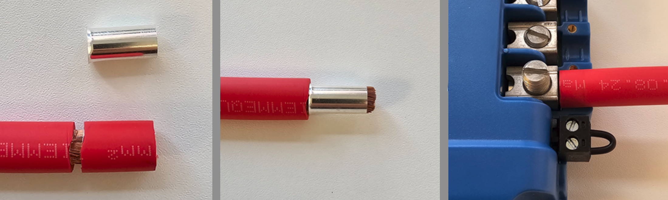
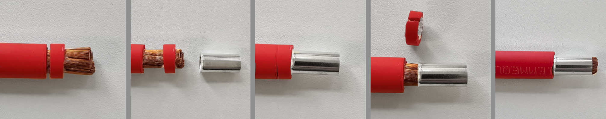
Tip
Tip for fitting a bootlace ferrule
Strip the insulation, leaving a narrow insulation ring attached to the conductor.
Slide the insulation ring to the stripped end to bundle the strands.
Fit the ferrule over the conductor while sliding the insulation ring back.
Remove the temporary insulation ring.
Position the ferrule fully onto the conductor.
3.4. Cable and fuse recommendations
External battery protection fuse | Minimum cable gauge | |
|---|---|---|
80 - 100 A | <10 m | |
25mm2 / 4AWG (21,2mm2) | ||
 | ||
3.5. Recommended torque

AWG | mm2 | in-lb | Nm |
|---|---|---|---|
4 | 25 | 50 | 5,6 |
6 - 10 | 16 - 6 | 40 | 4,5 |
8 - 12 | 10 - 4 | 25 | 2,8 |
For the cable cover use a torque of <0.7Nm (6 in-lb).
Screwdriver bit information
The screwdriver bit must have a blade thickness of 1,2 mm (0.046”) and minimal taper over at least the first 2 mm (0.08”) of engagement. This reduces the risk of cam-out and ensures correct torque transfer.
Common 6,3 mm (0.25”) screwdriver bits with a thinner 1 mm (0.04”) blade are not recommended.
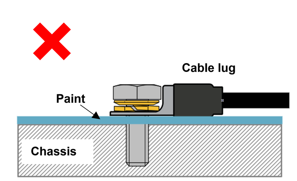
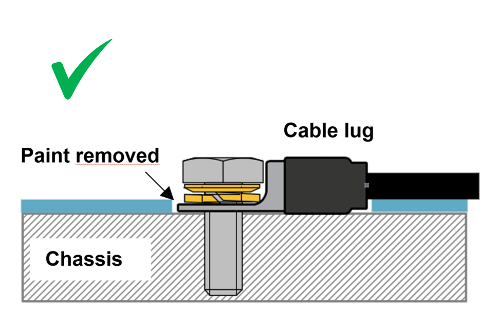
3.6. GND connection
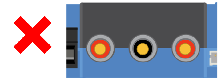
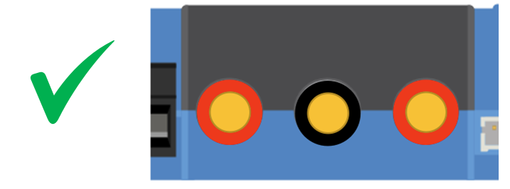
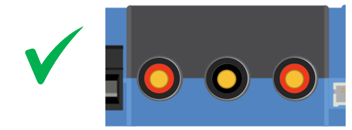
In many cases, the GND connection is connected to the chassis via a cable lug. For a low-impedance connection, the cable lug must have direct contact with the metal of the chassis, the contact surface must therefore be free of paint, see below images.
Important
Make sure the GND connection on the vehicle's chassis has a low impedance.
 |  |
3.7. Strain Relief
The connector type in this charger is sensitive to constant mechanical stress. Prolonged loading (pulling, pushing or twisting) of the connector should be avoided. For this reason, the charger is equipped with a strain relief in the cable cover. It is very important that the strain relief is applied correctly. The weight of the wire or other forces hanging from the connectors should be close to zero.
Caution
Insufficient strain relief can lead to connector damage in the long term.
The strain relief in the cable cover is designed so that wiring with an outer diameter >9mm is sufficiently clamped. With thinner wiring, the diameter must be increased to >9mm; this can be done simply by applying shrink tubing.
Wire diameter too small - not clamped | Wire diameter >9mm - properly clamped | Wire diameter increased >9mm - properly clamped |
|---|---|---|
 |  |  |
3.8. Connection setup for DC-DC power supply mode
Disconnect the remote on/off (remove the wire bridge or remove the entire remote on/off terminal block).
Connect the input power cables.
Open the VictronConnect app to set up the product (always adjust the output voltage before connecting a load or battery to the output).
For details, see Power supply mode settings.
Connect the load.
Reconnect the remote on/off to activate the product. The product is now ready for use.
Typical connection setting as DC-DC battery charger

3.9. Connection setup for charger mode
Disconnect the remote on/off (remove the wire bridge or remove the entire remote on/off terminal block).
Connect the input power cables.
Open the VictronConnect App to set up the product (always set up the correct charging algorithm before connecting a battery to the output).
For details, see Charger mode settings.
Connect the battery to be charged.
Reconnect the remote on/off to activate the product. The product is now ready for use.
Typical connection setting as DC-DC battery charger:
 |
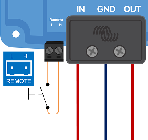
3.10. Connection setup for remote on/off
The recommended use of the remote on/off input is:
A switch wired between the L-H pins (ON switch level impedance between L-H pins: < 30kΩ)
A switch wired between (input/output) battery positive and H pin (ON switch level > 4V)
A switch wired between the L-pin and (input/output) ground (ON switch level < 6V)
BMS control via the H-pin (e.g. between BMS ATC output and H-pin)
Note
Note the voltage tolerance between L- & H-pin: +/- 70VDC
a) L-H pin wiring | b) H-pin wiring | c) L-pin wiring | |||
|---|---|---|---|---|---|
|
|
| |||
d) BMS control via H-pin | |||||
| |||||
Remote on/off connections | |||||
3.11. Wiring examples for BMS-controlled operation
To ensure smooth charging and prevent the risk of overcharging, the chargers must be controlled by the BMS. Depending on the BMS model, this control is either digital, via DVCC, or analogue, via the ATC contact.
DVCC-compatible BMS models
The BMS models listed below can control compatible chargers digitally via DVCC.
VE.Bus BMS V2
VE.Bus BMS NG
Lynx Smart BMS
Lynx Smart BMS NG
Note
DVCC compatibility requires Orion XS firmware v1.03 or later and Venus OS firmware v3.20 or later on the GX device.
Connect a VE.Direct cable between the Orion XS and the GX device and follow the DVCC instructions in the user manual of the BMS. There is no need to wire the BMS ATC contact to the remote H-pin. | 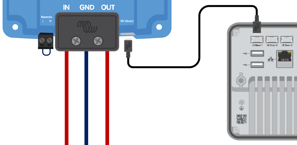 The Orion XS is controlled by DVCC via a GX device. |
Non-DVCC BMS models
The BMS models listed below control chargers via the ATC contact.
VE.Bus BMS
smallBMS with pre-alarm
smallBMS NG
Smart BMS 12-200
Smart BMS CL 12-200
Wire the BMS ATC contact to the remote H-pin. | 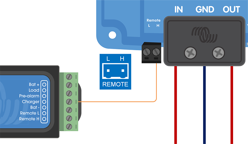 The Orion XS is controlled by the BMS ATC contact. |
Notice
Depending on the BMS model, the ATC contact may have a different name, such as "Charge Disconnect", "Charger" or "ATC". Please refer to the relevant section of the BMS manual.
3.12. Engine shutdown detection override wiring
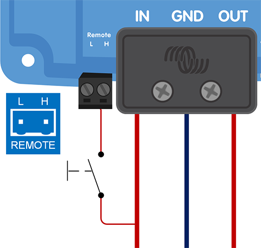
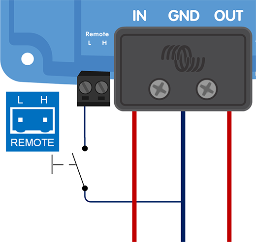
In charger mode, the engine shutdown detection sequence determines whether the conditions are met to enable charging; see the Engine shutdown detection chapter. Overriding the engine shutdown detection allows the user to decide for himself whether charging is allowed. Applying >8V to the L-pin overrides the engine shutdown detection and activates the charger. This can be done, for example, with an ignition switch, CAN-bus engine running detector, etc.
Notice
This function does not override the remote on/off function. Remote connection a), b) or d), as shown in section Connection setup for remote on/off, must be configured in combination with engine shutdown detection override. See examples in the below images.
Enable charging via an ignition switch i.c.w. remote on/off option a) | Enable charging via an ignition switch i.c.w. external on/off option (e.g. BMS ATC contact) d) |
|---|---|
 |  |
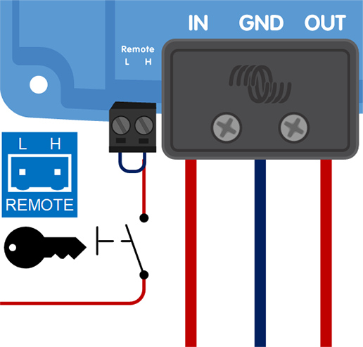 | 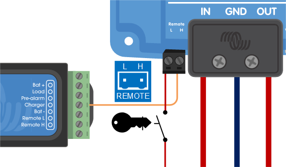 |
Engine shutdown detection override connection diagram
Note
When the ignition switch is switched off, the charger will return to engine shutdown detection mode, it will not turn off the charger.
To force enable/disable charging (i. e. turn the Orion XS on/off) without interference from the engine shutdown detection, a remote option as given in section Connection setup for remote on/off must be wired, and the engine shutdown detection must be switched off in VictronConnect, see figure below.
 |  |  |
Disable engine shutdown detection
Warning
When the engine shutdown detection has been switched off in Victron Connect (‘forced charging’), current will be drawn from the starter battery even if the engine is not running.
Note
During ‘forced charging’ the input voltage lockout is the only limit left to disable charging automatically, make sure this level is not set too low, in most applications 12.5V is sufficiently low.