4. Installation
Warning
The DC (PV) input is not isolated from the battery circuit. Therefore the PV, battery and control circuit are considered hazardous and should not be user accessible.
Caution
For proper temperature compensated battery charging the ambient temperature of the solar charger and the battery must be within 5°C (9°F).
Caution
The battery and PV connections must be guarded against inadvertent contact. Install the solar charger in an enclosure or install the optional WireBox.
4.1. Mounting
Mount the solar charger vertically on a non-flammable substrate, with the electrical terminals facing downwards.
The Dimension drawings chapter of this manual contains the dimension drawing of the solar charger, this drawing also indicates the mounting holes.
Observe a minimum clearance of 10cm under and above the solar charger for optimal cooling.
Mount the solar charger within 3 meters from the battery, but never directly above the battery. This is to prevent damage due to gassing of the battery.
Caution
Avoid ambient temperature differences of more than 5°C between the solar charger and the battery. These temperature differences can lead to incorrect temperature compensated charging, which can reduce the battery lifetime.
If large temperature differences or extreme ambient temperature conditions are expected, use a direct battery temperature sense source like the Smart Battery Sense or a BMV or SmartShunt equipped with a temperature sensor.
If the optional MPPT WireBox is used:
Affix the steel WireBox base to the solar charger before the solar charger is mounted into its final position.
For full mounting instructions, see the MPPT WireBox TR quick installation guide.
4.2. Battery
The battery supply must be protected by a fuse as per the below table. This is also the case even if the solar charger has already been equipped with an external fuse.
Solar charger type | Minimum battery fuse rating | Maximum battery fuse rating |
|---|---|---|
MPPT 75/10 | 15A | 20A |
MPPT 75/15 and 100/15 | 20A | 25A |
MPPT 100/20 | 25A | 30A |
Notice
For Canada the battery fuse must comply with the C22.2 standards.
Notice
The battery installation must be done in accordance with the local storage battery rules. For Canada this is the Canadian Electrical Code, Part I.
Notice
Use flexible multi stranded copper cable for the battery connections Also see chapter Wiring safety precautions.
4.3. PV array
The solar charger can be used with a PV configuration that satisfies both these two conditions:
The maximum open circuit PV voltage can not exceed 75V or 100V, depending on the solar charger model.
The nominal PV voltage should be at least 5V higher than the battery voltage.
The PV array can consist of mono- or poly-crystalline panels.
The solar panels are connected in series, in parallel or in series/parallel. See below figure for examples of these configurations.
 |
Examples of series, parallel and series/parallel solar arrays.
To help calculate the size of the PV array configuration use the MPPT sizing calculator. Alternatively, use one of these PV array configurations:
PV array example 12V battery with 75V solar charger:
Minimum number of cells in series: 36 (12V panel).
Recommended number of cells for highest controller efficiency: 72 (2x 12V panel in series or 1x 24V panel).
Maximum: 108 cells (3x 12V panel in series).
PV array example 24V battery with 100V solar charger:
Minimum number of cells in series: 72 (2x 12V panel in series or 1x 24V panel).
Maximum: 144 cells (4x 12V panel in series).
Important
Provide a means to disconnect all current-carrying conductors of a photo-voltaic power source from all other conductors in a building or other structure.
Careful: when calculating the number of panels that can be used in series, make sure to take both its Open circuit voltage (Voc) and its Temperature coefficient into account. At ambient temperatures below 25°C, the Voc will be higher.
A switch, circuit breaker, or other device, either AC or DC, shall not be installed in a grounded conductor if operation of that switch, circuit breaker, or other device leaves the grounded conductor in an un-grounded state while the system remains energized.
Do not use solar panels with optimizers. In worst case, the use of optimizers will cause irreparable damage to the solar charger.
Use flexible multi stranded copper cable for the screw connections . See chapter Wiring safety precautions.
4.4. Grounding
Battery grounding
The solar charger can be installed in a positive or in a negative grounded system.
Apply a single ground connection, preferably close to the battery, to prevent system issues or ground loops.
Chassis grounding (only for the 20A model)
A separate ground path for the chassis ground is permitted because the chassis is isolated from the positive and the negative terminals.
PV array grounding
The positive and negative of the PV array should not be grounded.
Ground the frame of the PV panels to reduce the impact of lightning.
Do not connect the solar charger to a grounded PV array. Only one ground connection is allowed, and this should be near the battery.
Ground fault detection
The system electrical negative should be bonded through a GFDI to earth ground at one (and only one) location.
Warning
WARNING: When a ground fault is indicated, battery terminals and connected circuits may be ungrounded and hazardous.
4.5. Connection overview
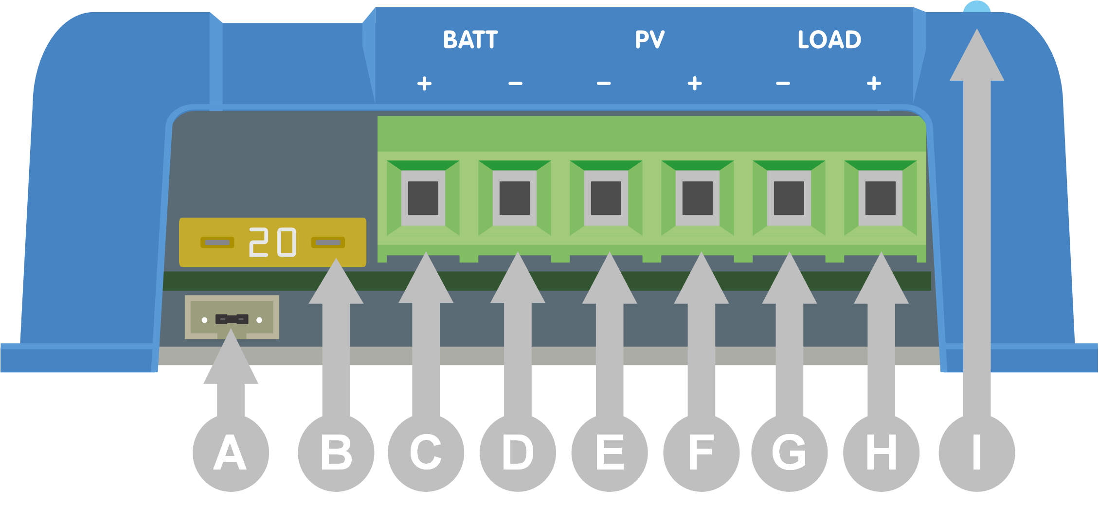 | ||||||||||||||||||||
|
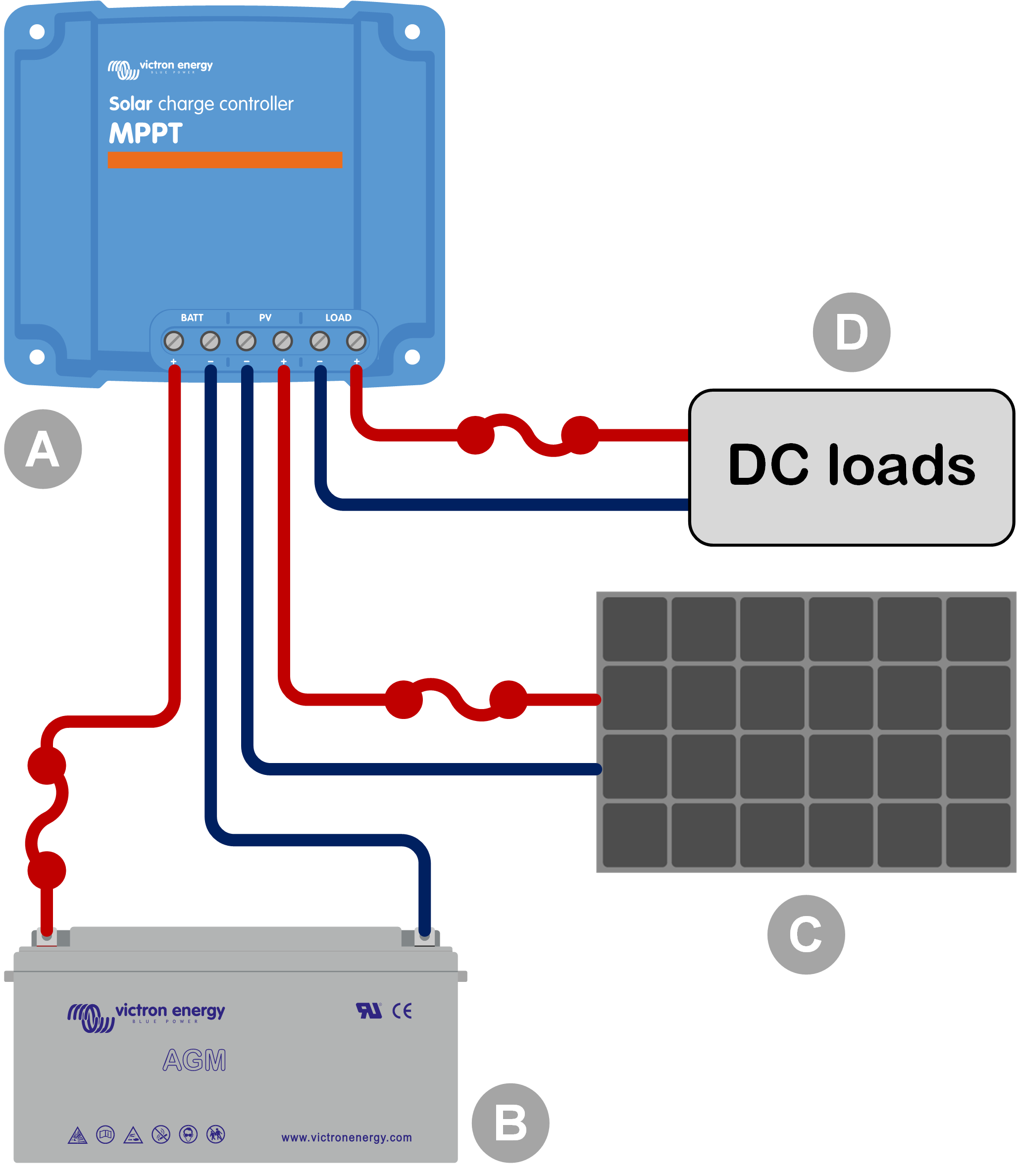
4.6. Electrical connections
Warning
WARNING: Check the polarity before connecting the battery and PV voltage.
WARNING: Follow the correct installation procedure described in this chapter.
IMPORTANT: Torque the battery, load and PV connections at 0.75Nm.
Connection order electrical connections:
Connect the battery: allow the solar charger to automatically recognise the system voltage (wait 10 seconds).
It is recommended to verify system voltage: use VictronConnect or an external control display.
Connect the DC loads.
Connect the PV.
If applicable, connect the VE.Direct port.
The correct connection order is necessary to allow the automatic system voltage detection to setup properly. It is only allowed to connect PV first when the system voltage is manually set before connecting the battery. Not following the correct procedures can disable or damage the charger and/or the installation.
See the below figure on how the basic electrical connections are made:
| ||||||||||||||
| ||||||||||||||

4.7. Connect the MPPT Control display
Connect the (optional) MPPT Control display to the VE.Direct port of the solar charger using a VE.Direct cable.
The VE.Direct cable is available in a variety of lengths and is not included with the MPPT control display. Note that it is not possible to extend the VE.Direct cable, the maximum length can not exceed 10 meters.
For more information, see the MPPT Control manual.
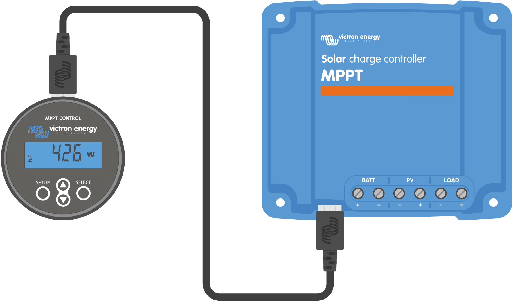
Connect the display to the solar charger via a VE.Direct cable