- 3.1. What's in the box
- 3.2. Connections overview
- 3.3. AC Input configuration
- 3.4. AC output configuration
- 3.5. Connecting AC input and AC output
- 3.6. AC output neutral to earth link
- 3.7. Cable cross-section requirements
- 3.8. Wiring example
- 3.9. Linking input and output earth when the vessel is out of the water.
The isolation transformer ships with the following items:
Description |
|---|
1x hanging bracket, used for mounting the isolation transformer inside a vessel. |
1x isolation transformer. |
1x long yellow/green jumper wire with female 6.35 mm spade connectors, used to connect AC input earth (PE) to AC output earth (PE) when the vessel is out of the water for maintenance or winter storage. |
1x long yellow/green wire with eye terminals, used for case grounding (not included for the 2000W model). |
1x short yellow/green jumper wire with female 6.35 mm spade connectors, used to make AC output neutral (N) to earth (PE) link. |
4x short black jumper wires with 6.35 mm female spade connectors, used for AC configuration. |
7x mounting screws for the 3600W model and 4x mounting screws for the 2000W model. |
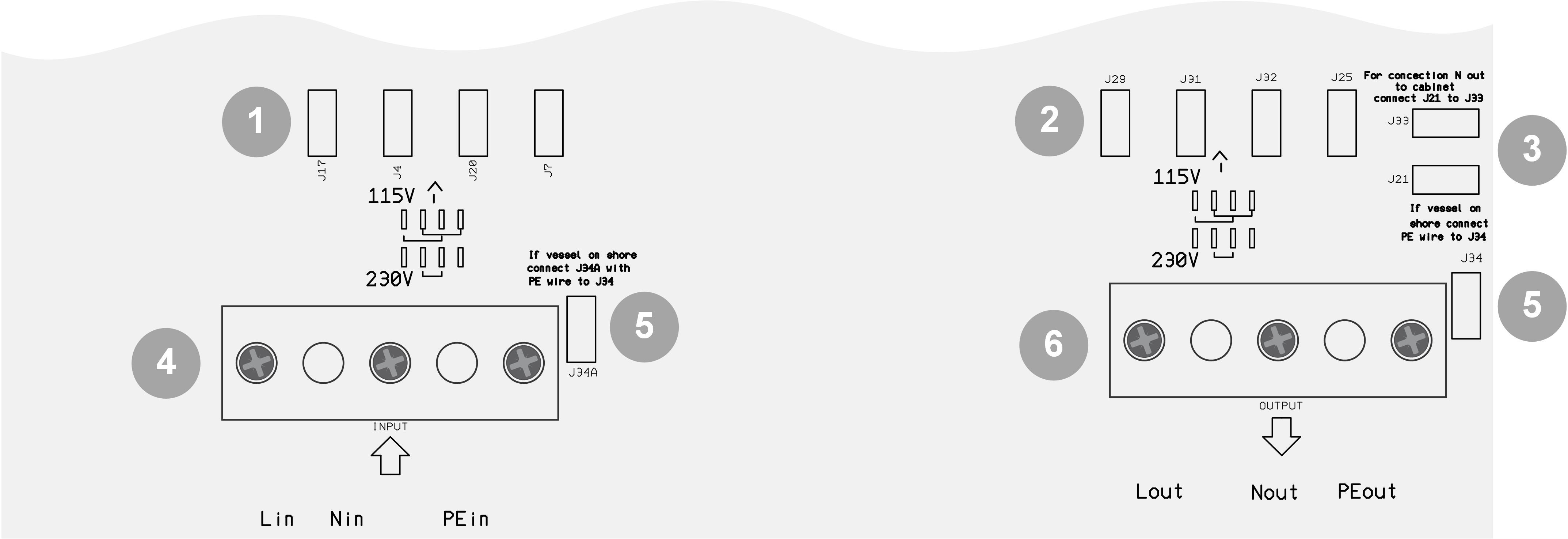
ID | Description |
|---|---|
1 | Male spade terminals to configure the AC input voltage: For 115V, connect J17 to J20 and connect J4 to J7. For 230V, connect J4 to J20. |
2 | Male spade terminals to configure the AC output voltage: For 115V, connect J29 to J32 and connect J31 to J25. For 230V, connect J31 to J32. |
3 | Male spade terminals to establish an AC output neutral to earth connection link for a correct operation of an AC output GFCI: J33 and J21. |
4 | AC input terminal (shore power) : Phase (L) neutral (N) and earth (PE). |
5 | Male spade terminals to bridge AC input earth to AC output earth when the vessel is out of the water: J34A and J34. |
6 | AC output terminal (AC loads or AC installation): Phase (L) neutral (N) and earth (PE). |
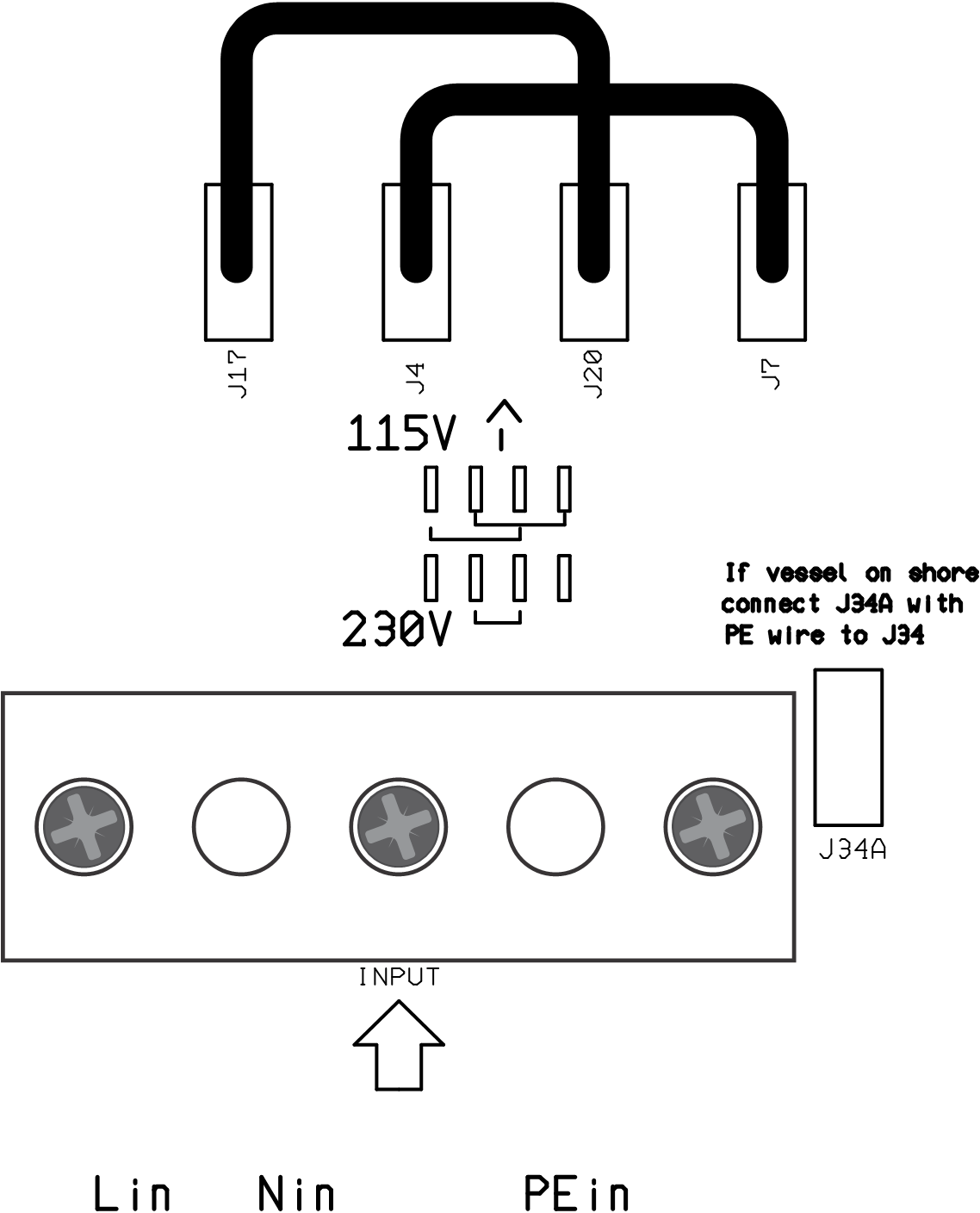
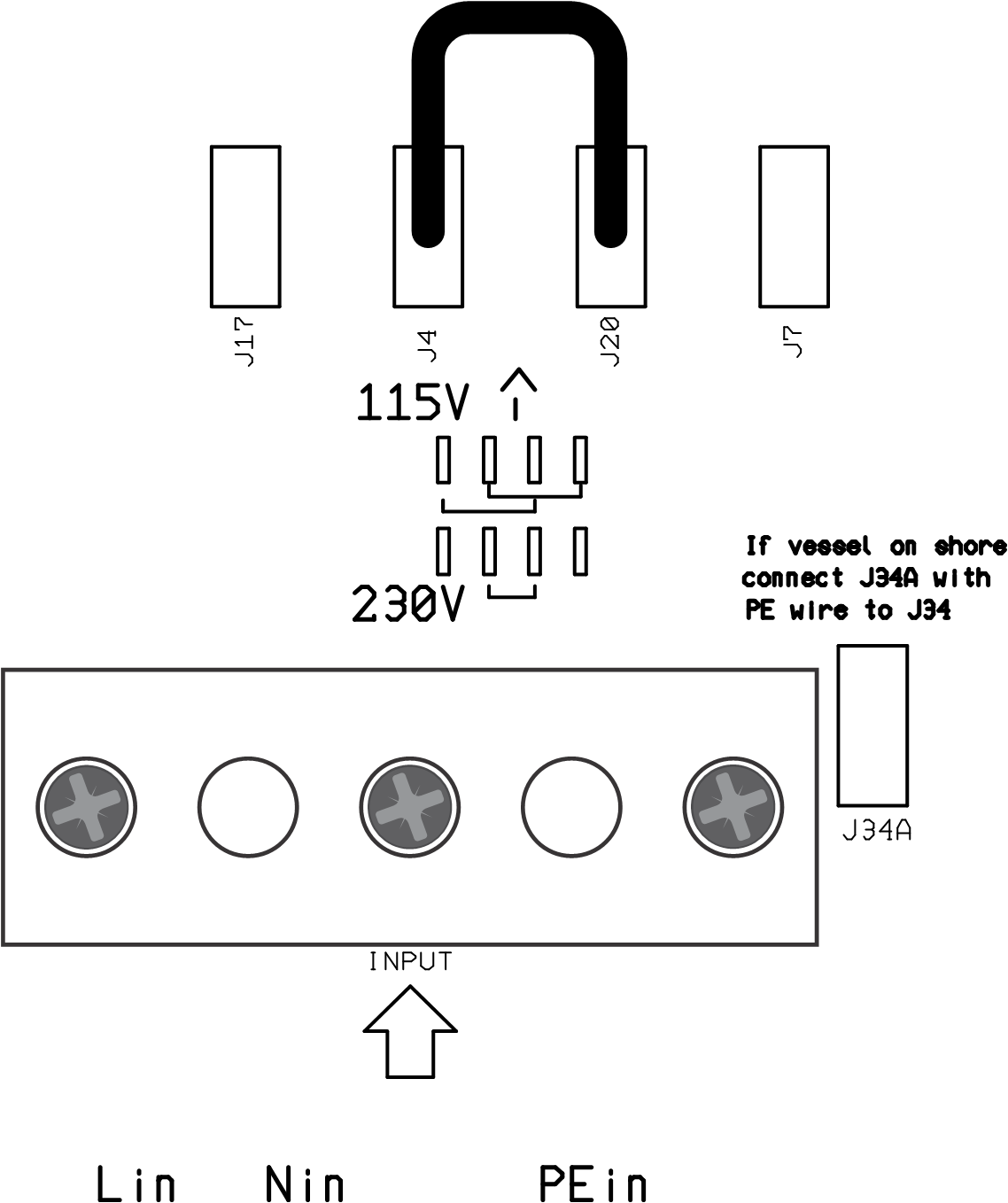
The AC input needs to be configured for 115 or 230V use. This is done by connecting male spade terminals using the black jumper wires (included). These terminals are located above the AC input connector.
AC input voltage | Connect jumper cable between | Connections | |
|---|---|---|---|
115V | J17 and J20 J4 and J7 |
| |
230V | J4 and J20 |
|
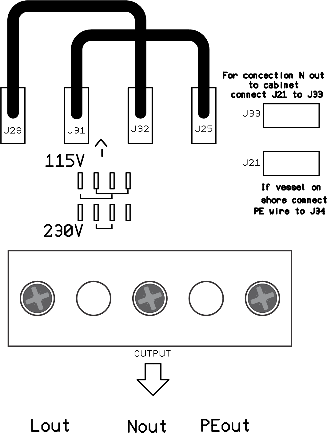
The AC output needs to be configured for 115 or 230V use. This is done by connecting male spade terminals using the black jumper wires (included). These terminals are located above the AC output connector.
AC output voltage | Connect jumper cable between | Connections | |
|---|---|---|---|
115V | J29 and J32 J31 and J25 |
| |
230V | J31 and J32 |
|
Warning
Shock hazard. Do not work on the isolation transformer or the electrical system if still connected to an electrical power source.
Connection sequence:
Pass the AC cables through the cable glands at the bottom of the cabinet in the following way:
Pass the AC input (shore power) cable through the left side cable gland.
Pass the AC output (AC loads) cable through the right side cable gland.
Connect the AC input cable to the INPUT terminal block in the following way:
Connect the earth wire to the PE terminal.
Connect the neutral wire to the N terminal.
Connect the phase wire to the L terminal.
Connect the AC output cable to the OUTPUT terminal block in the following way:
Connect the earth wire to the PE terminal.
Connect the neutral wire to the N terminal.
Connect the phase wire to the L terminal.
Connect the enclosure to the ground (=all the metal parts in the vessel) in the following way:
Connect the M6 bolt underneath the enclosure to the vessel ground. See the below drawing for the location of the chassis earth bolt.

Location of the chassis earth bolt.
A GFCI must be installed in the AC output of the isolation transformer. For the GFCI to operate correctly, the AC output neutral must be connected to the AC output earth and ground (= all the metal parts in the vessel).
To link the AC output neutral (N) to earth (PE), place a green/yellow jumper wire (included) between the J33 and J21 male spade connectors.
AC output neutral (N) to earth (PE) link.
Use the following minimal cable cross-sections:
Isolation transformer power rating | Voltage | Metric | AWG |
|---|---|---|---|
2000W | 115V | 2.5mm² | AWG 13 |
2000W | 230V | 1.5mm² | AWG 16 |
3600W | 115V | 6mm² | AWG 10 |
3600W | 230V | 2.5mm² | AWG 13 |
Wiring example isolation transformer installed on a vessel connected to shore power.
ID | Description |
|---|---|
A | Shore power. |
B | Circuit breaker. |
C | GFCI (Ground Fault Circuit Interrupter). |
D | Shore cable. |
E | Isolation transformer. |
F | AC loads. |
For safety reasons, when the vessel is out of the water (on land) during winter or for maintenance, the vessel's earth (PE) conductor must be connected directly to the shore power earth (PE) conductor.
This can be achieved inside the isolation transformer by connecting the yellow/green jumper wire (included) between male spade terminals J34A and J34, as indicated below.
AC input earth is connected to AC output earth when the vessel is out of the water (on land) during winter or for maintenance.