5. Configuration
5.1. Configuring via the VictronConnect app
The VictronConnect app can be used to change all settings and to update the firmware.
The VictronConnect app can connect to the inverter via:
Local - via built in Bluetooth
Local - via USB using the VE.Direct to USB interface connected to the VE.Direct port.
Local - via Bluetooth using the VE.Direct Bluetooth Smart dongle connected to the VE.Direct port.
Remotely - via the VRM portal and a GX device. (see VRM tab in the VictronConnect device list).
How to connect to the inverter with the VictronConect app:
Open the VictronConnect app
Ensure that the inverter is powered
Look for the inverter to appear in the device list in the "Local" or the "VRM" tab
Click on the inverter.
In case of a connection via Bluetooth; Enter the default PIN code, which can be found on the product information sticker.
To view and/or change battery monitor settings:
Navigate to the settings page by clicking on the cog icon
 at the top right of the home screen.
Tip
This manual only covers the inverter specific items. For more general information on the VictronConnect app, like how use it, where to download it or how to connect, see the VictronConnect app product page and the VictronConnect manual or scan below QR code:
 |
5.2. Battery settings
Battery voltage
The Inverter RS Smart is fixed to 48V, and is only available for 48V systems.
Battery Capacity
Capacity of the connected battery pack in AmpHours. This is used by the internal battery state of charge calculation.
Max charge current
Allows the user to set a lower maximum charge current.
Charger settings - Battery preset
Battery preset allows you to select the battery type; accept factory defaults; or enter your own preset values to be used for the battery charge algorithm. The Absorption voltage, Absorption time, Float voltage, Equalisation voltage and Temperature compensation settings are all configured to a preset value - but can be user-defined.
Built-in preset: select of the built-in presets (Normal, High and LiFePO4 2-wire BMS)
User defined: all parameters can be customized manually
Select preset: select a type from the VictronConnect battery presets
Create preset: create a new battery preset in VictronConnect
Edit presets: edit an existing battery preset in VictronConnect
User-defined presets will be stored in the preset library - in this way installers will not have to define all the values each time they are configuring a new installation.
By selecting Edit Presets, or on the Settings screen (with expert mode on or not), custom parameters can be set as follows:
Battery Chemistry
OPzS/OPzV
Gel/AGM
Lithium (LiFePO4)
Remote Mode
Configure what is connected to the REMOTE_L and REMOTE_H inputs on the user connector.
Remote on/off: a simple on/off switch
2-wire BMS: wired BMS with allow-to-charge and allow-to-discharge signals like the SmallBMS. Note if 2-wire BMS is selected, then the unit will not start up until one is connected.
Expert mode
This on/off toggle enables editing expert settings in case your equipment has special requirements.
BMS controlled
This item is only visible in case the unit is controlled remotely by a BMS. Click to change/view, this opens a new menu, described further down in the document.
Low SOC shutdown
Shutdown on low SOC, switch off the inverter in case the battery state of charge drops below a certain SOC value, and restarts above a certain SOC value.
Dynamic cut off
Default is disabled. Click to enable, this opens a new menu, described further down in the document.
Low battery shut down voltage
Once dynamic cut-off is enabled this setting is controlled internally, it is no longer editable. When the battery voltage drops below this level the inverter switches off. If there is no power source available like PV power or the grid (in case of a Multi RS variant), the unit goes into hibernate to preserve as much power as possible.
Low battery restart & alarm
When the battery voltage drops below this level a low battery warning is shown. In case the inverter switched off due to a low battery voltage alarm it will restart again once the battery voltage rises above this level.
Charge detect
In case the inverter keeps switching off and on repeatedly due to low battery voltage the switch on level rises to the charge detect voltage. This ensures that the battery is really charging before switching the inverter back on.
Absorption voltage
Set the absorption voltage.
Float voltage
Set the float voltage.
Equalization voltage
Set the equalization voltage.
Storage Voltage
Set the storage voltage
Re-bulk voltage offset
Set the voltage offset that will be used over the float voltage setting that will determine the threshold that the charge cycle will restart.
E.g.: For a Re-bulk voltage offset off 0.4V and a float voltage setting of 54.0 V, the voltage threshold that will be use to restart the charge cycle will be 53.6 V. In other words, if the battery voltage drops below 53.6 V for one minute, the charge cycle will restart.
Adaptive absorption time
Select with adaptive absorption time or fixed absorption time will be used. Both are better explained below:
Fixed absorption time: The same length of absorption is applied every day (when there is enough solar power) by using the maximum absorption time setting. Be aware that this option can result in overcharging your batteries, especially for lead batteries and system with shallow daily discharges. See your battery manufacturer for recommended settings. Note: make sure to disable the tail current setting to make the same absorption time every day. The tail current could end absorption time sooner if the battery current is below the threshold. See more information on the tail current setting section below.
Adaptive absorption time: The charge algorithm can use an adaptive absorption time: it automatically adapts to the state of charge in the morning. The maximum duration of the absorption period for the day is determined by the battery voltage as measured just before the solar charger begins operation each morning (12 V battery values used - Multiply Battery voltage by 4 for 48V ):
Battery voltage Vb (@start-up) | Multiplier | Maximum absorption times |
|---|---|---|
Vb < 11.9 V | x 1 | 06:00 hours |
> 11.9 V Vb < 12.2 V | x 2/3 | 04:00 hours |
> 12.2 V Vb < 12.6 V | x 1/3 | 02:00 hours |
Vb > 12.6 V | x 2/6 | 01:00 hours |
The multiplier is applied to the maximum absorption time setting and this results in the maximum duration of the absorption period used by the charger. The maximum absorption times shown in the last column of the table are based on the default maximum absorption time setting of 6 hours.
Maximum absorption time (hh:mm)
Set the absorption time limit. Only available when using a custom charge profile.
Enter the time value in the notation hh:mm, where hours are between 0 and 12; and minutes are between 0 and 59.
Tail current
Set the current threshold that will be used to finish absorption phase before the maximum absorption time expires. When the battery current gets below the tail current for one minute, the absorption phase will end. This setting can be disabled by setting it to zero.
Equalization current percentage
Set the percentage of the Max charge current setting that will be used when equalisation is performed.
Automatic Equalization
Set-up the frequency of the auto equalize function. Available options are between 1 and 250 days:
1 = daily
2 = every other day
...
250 = every 250 days
Equalization is typically used to balance the cells in a lead battery, and also to prevent stratification of the electrolyte in flooded batteries. Whether (automatic) equalization is necessary, or not, depends on the type of batteries, and their usage. Consult your battery supplier for guidelines.
When the Automatic equalization cycle has initiated, the charger applies an equalization voltage to the battery as long as the current level stays below the equalization current percentage setting of the bulk current.
Duration of the Automatic equalization cycle
In the case of all VRLA batteries and some flooded batteries (algorithm number 0, 1, 2 and 3) automatic equalization ends when the voltage limit (maxV) has been reached, or after a period equal to (absorption time/8) - whichever comes first.
For all tubular plate batteries (algorithm numbers 4, 5 & 6); and also for the user-defined battery type, automatic equalization will end after a period equal to (absorption time/2).
For the Lithium battery type (algorithm number 7), equalization is not available.
When an automatic equalization cycle is not completed in one day, it will not resume the next day. The next equalization session will take place according to the interval set in the 'Auto Equalization' option.
The default battery type is a VRLA battery and any user-defined battery will behave as a tubular plate battery with regard to equalization.
Equalisation stop mode
Set how the equalisation will end. There are two possibilities, first is if the battery voltage reaches the equalisation voltage and the second is on fixed time, where the maximum equalisation duration is used.
Maximum equalisation duration
Set the maximum time that the equalisation phase will last.
Temperature compensation
Many types of battery require a lower charge voltage in warm operating conditions, and a higher charge voltage in cold operating conditions.
The configured coefficient is in mV per degree Celsius for the whole battery bank, not per cell. The base temperature for the compensation is 25°C (77°F), as shown in the chart below.

With a temperature sensor installed to the User I/O connection block; the actual battery temperature will be used for compensation; throughout the day.
Low temperature cut-off
This setting can be used to disable charging at low temperatures as required by Lithium batteries.
For Lithium Iron Phosphate batteries this setting is preset at 5 degrees Celsius, for the other battery types it is disabled. When creating a user defined battery the cut-off temperature level can be adjusted manually.
Manual Equalization - Start now
Selecting 'Start now' on 'Manual equalisation' allows manual initiation of an Equalization cycle. To allow the charger to equalize the battery properly use the manual equalize option only during absorption and float periods, and when there is sufficient sunlight. Current and voltage limits are identical to the automatic equalize function. The duration of the equalisation cycle is limited to a maximum of 1 hour when triggered manually. Manual equalization can be stopped at any time by selecting 'Stop Equalize'.
5.2.1. Battery Monitor
The parameters below are only used when the unit must determine the state of charge on its own. Please refer to the BMV manual for more detailed explanation of these values. In case a BMV or Managed Battery (BMS) is used it uses the remote state of charge and the internal mechanism is no longer used.
Peukert exponent
Charge efficiency factor
Discharge floor
Synchronize SOC to 100%
press synchronize to preset the internal state of charge to 100%
5.2.2. Dynamic cut off
This is a sub-menu available in the battery settings.
Dynamic cut-off makes the low battery shut down voltage a function of the load of the battery. Don't use dynamic Cut-off in an installation that also has other loads connected to the same battery.
Enable dynamic cutoff: toggle between on or off
Voltage discharge current 2A: battery voltage.
Voltage discharge current 100A: battery voltage.
Voltage discharge current 280A: battery voltage.
Voltage discharge current 800A: battery voltage.
5.2.3. BMS control
This is a sub-menu available in the battery settings. It only shows up in case the unit is remotely controlled by a BMS. This sub-menu is not present/enabled in case you are using the 2-wire BMS inputs.
Use the RESET function to restore the unit back to standalone operation in case you are using the unit in a different installation. This clears the warning indication #67 BMS connection lost.
In case the unit is placed back into a setup with an external control BMS the function will be activated automatically.
5.3. Inverter settings
The following inverter settings can be configured:
Setting | Explanation | Default | Range |
|---|---|---|---|
Output voltage | Inverter AC output voltage | 230V | 210V to 245V |
Output frequency | Inverter AC output frequency | 50Hz | 50Hz or 60Hz |
Ground relay | When this setting is enabled, Neutral (N) will be connected to protective earth (PE) when the inverter is operational. This connection will be broken when the inverter is not operational. When this setting is disabled, neutral (N) will never be connected to protective earth (PE). | enabled | enabled or disabled |
5.4. Programmable relay
Programmable relay which can be set for general alarm, DC under voltage or genset start/stop function. DC rating: 4A up to 35VDC and 1A up to 70VDC
5.5. Connecting to external AC PV inverters
The Inverter RS Smart includes a built in AC PV inverter detection system. When there is a feedback of AC PV (a surplus) from the AC-out connection port, the Inverter RS Smart will automatically enable an AC output frequency adjustment.
While no further configuration is required, it is important that the AC PV inverter is configured correctly to respond to the frequency adjustment by reducing its output.
Note the 1:1 rule of AC PV inverter size to Inverter RS Smart size, and minimum battery sizing applies. More information about these limitations are available in the AC Coupling manual, and this document is required reading if using an AC PV inverter.
The frequency adjustment range is not configurable, and includes a built in safety margin. Once the absorption voltage is reached, the frequency will increase. So it is still essential to include a DC PV component in the system for complete battery charging (i.e. float stage).
The PV inverter stop frequency (fstop) is 53.2Hz. This is not configurable.
It may be possible to adjust the power output response to various frequencies on your AC PV inverter.
The default configuration has been tested and works reliably with the Fronius MG50/60 grid code configuration.
5.6. Parallel programming
Inverters must be installed correctly before configuration.
To set up a parallel system, open the first unit in VictronConnect. Open the Settings - System menu.
Caution
AC output power will be disconnected for a few seconds when switching System configuration modes. Make sure the system is configured BEFORE connecting inverter AC output to the loads.
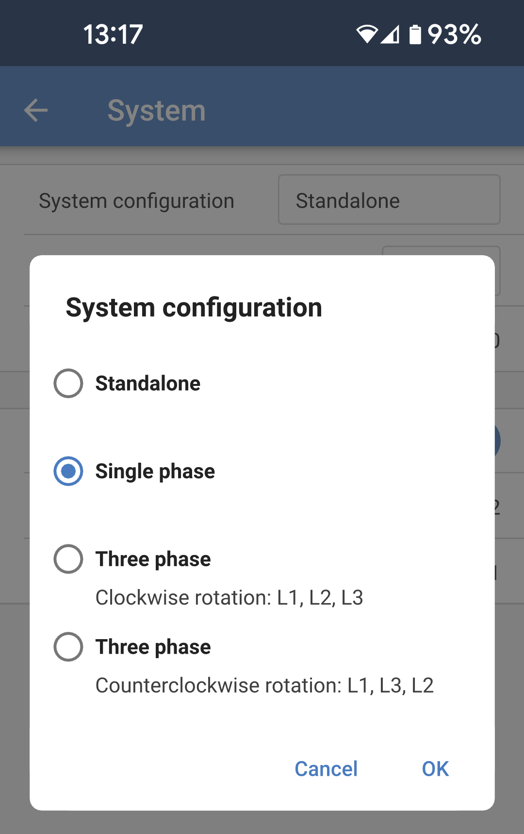
The factory default setting is Standalone (a single unit).
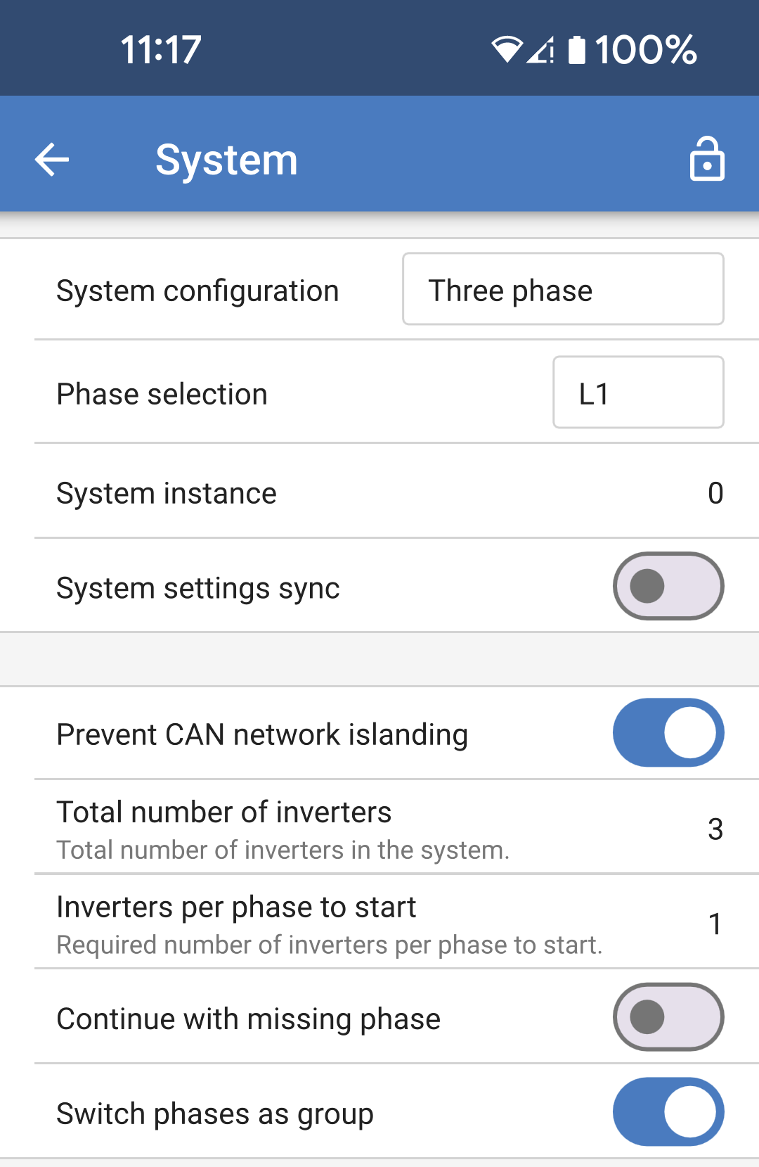
To set up a parallel system on a single phase, change the System configuration to "Single phase".
To set up parallel for three phase systems, select "Three phase". This setting is the same for a three phase system with a single inverter on each phase, or multiple on each phase.
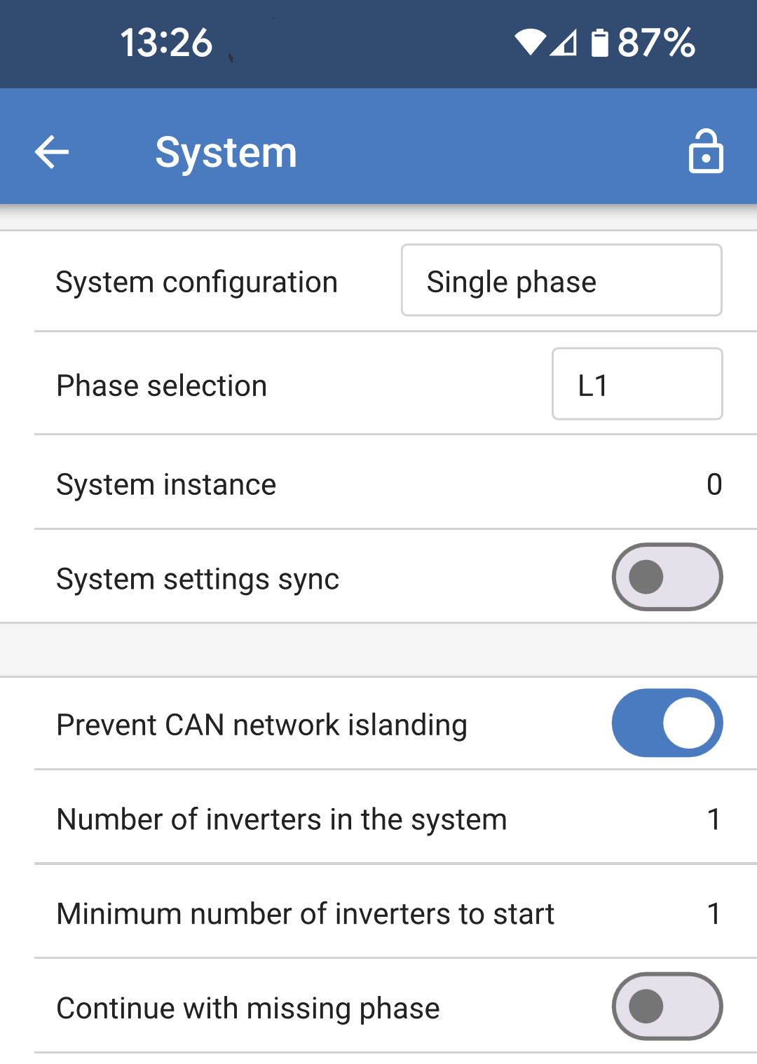
Prevent CAN network islanding toggle
This setting determines what the system does in case of a broken CAN connection between the RS units, and enables the 'Number of inverters in the system' setting below. Default is enabled.
Number of inverters in the system
Enter the total number of units installed in the system.
In case the CAN network is split into segments this setting is used to determine the largest and shut down the smaller segment to prevent them from continuing on their own unsynchronised.
This results in a more reliable system than if the smaller segment tried to continue on its own unsynchronised (which will lead to overload or other less graceful shutdown issues caused by an unsynchronised AC output sine wave).
In parallel systems where there are only 2 units, having an additional VE.Can device that is recognised by the RS with the same System instance assists with determining which islanded system will power on. This additional VE.Can device can be GX device, Lynx BMS, or another DC coupled VE.Can MPPT charger.
In this case a single inverter can still start if the other one is not communicating, as long as 'Prevent CAN network islanding' is disabled.
Minimum number of inverters to start
Minimum number of inverters that must be present per phase when starting the system.
This is set by the installer to ensure that there are sufficient units to start up the expected system load powering on at once.
You may want to require all, or all minus one (to still allow for a system restart if a single unit is offline), or only 1 for maximum redundancy presuming there is no large start up loads.
Once the system starts it will not shutdown if the number of inverters operational per phase drops below this setting (as long as the remaining inverters do not overload and can continue to power the load).
If the 'Prevent CAN networking islanding' setting is enabled, the system will remain online until the number of inverters falls below the 'Number of inverters in the system' value divided by 2 + 1 (which is the threshold for the CAN network island protection).
If the 'Prevent CAN network islanding' setting is disabled, then the system will not shut down automatically even if only a single inverter per phase remains online.
For further details about redundancy and the implications of "Continue with a missing phase" setting - see the 3 phase programming chapter.
System Instance
Units with the same instance number work together on the AC side.
Changing the System instance setting allows multiple groups of Inverters to be on the same VE.Can bus, but not synchronised, and segmented into different AC outputs, without interference.
Continue with the same programming settings on the rest of the units.
Note
These System settings must be programmed individually, and set correctly on all connected inverters for synchronised operation.
Note on redundancy and continuous output during firmware updates
The AC synchronisation mechanism used for parallel and 3 phase has a 'protocol' version embedded.
Units can work together even with different firmware versions, as long as they are running the same protocol version.
This allows for continuous uninterrupted supply even when updating firmware, as the units will individually update one at a time, while others continue to synchronise and provide the stable AC output.
If Victron needs to change the 'protocol' version number, it will be clearly noted in the firmware change log. Always read this before updating.
In the event that there are multiple protocol versions running on the same VE.Can bus, all units will indicate error #71 until they are all updated to the same version.
Note
Capacity will be reduced during firmware updating as units are individually turned off and restarted to update their firmware.
There is an additional setting for 3 phase systems that controls if the other two phases shut down if one of the phases is offline. See 3 phase programming for more information.
5.7. 3 phase programming
In order to configure a 3 phase system the Inverter RS Smart will need to be correctly installed, and running firmware version v1.13 or later.
Configuring a system for three phase or single phase is done in VictronConnect in the System menu.
Caution
AC output power will be disconnected for a few seconds when switching System configuration modes. Make sure the system is configured BEFORE connecting inverter AC output to the loads.
Note
These System settings must be programmed individually, and set correctly on all connected units for synchronised operation.
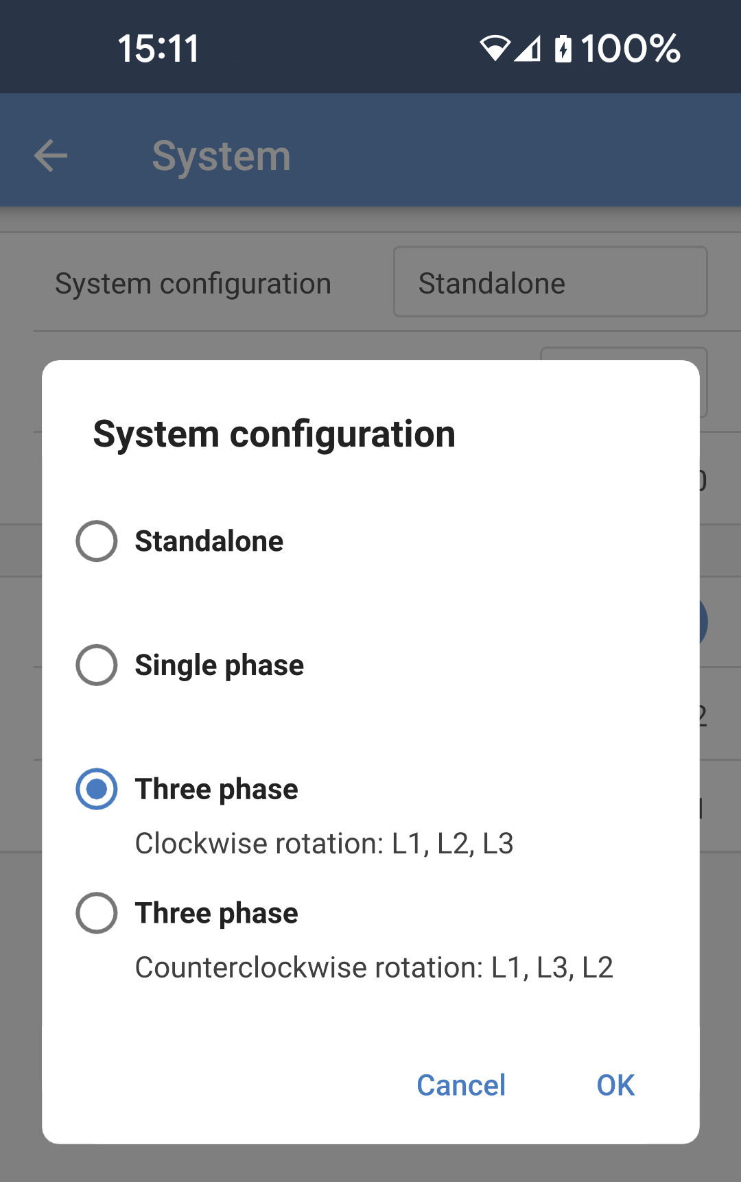
The factory default System configuration setting is "Standalone". Tap the box to bring up a popup menu where you can select "Three phase". There are two three phase options to choose from, either clockwise or counter clockwise, depending upon the phase rotation at the installation site. You'll need to apply these same settings to each unit individually. |
|
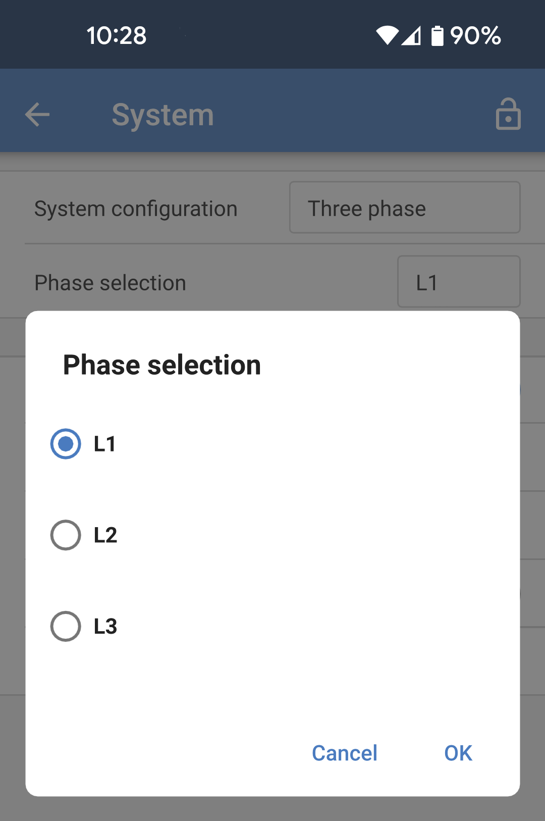
Select the correct phase that each particular unit is connected to. There can only be one unit per phase. Do this for each individual unit. It is also advisable to physically label each unit and also give a matching custom name in the product info settings. |
|
|
|
Note on redundancy and continuous output during firmware updates
A three phase system can be firmware updated without losing power on the AC output.
Make sure that there is stable AC input available when starting the update and the unit currently being updated will switch to AC-passthrough mode.
The AC synchronisation mechanism used for 3 phase has a 'protocol' version embedded.
Units can work together even with different firmware versions, as long as they are running the same protocol version.
This allows for continuous uninterrupted supply even when updating firmware, as the units will individually update one at a time, while others continue to synchronise and provide the stable AC output.
If Victron needs to change the 'protocol' version number, it will be clearly noted in the firmware change log. Always read this before updating.
In the event that there are multiple protocol versions running on the same VE.Can bus, all units will indicate error #71 until they are all updated to the same version.
Known Issues
The 'UPS function' is too sensitive in 3 phase operation compared to stand-alone operation. Disable the 'UPS function' in case the Multi disconnects frequently from the AC input.
Charge currents are not yet balanced across the 3-phases when the charger is in voltage-controlled mode.