3. System design
Designing the system is a matter of making a few decisions in sequence. Each decision narrows the design, and together they determine the topology and the components needed. This chapter takes those decisions in order: how the installation connects to the grid, whether it is single-phase or multiphase, which inverter/charger suits the loads, how large the battery bank needs to be, how solar is integrated, whether surplus solar is fed back to the grid, and what the local grid connection requires for anti-islanding.
3.1. Grid arrangement
The first design decision is how the installation connects to the grid. It comes down to where the loads and any PV inverters are connected, and that in turn determines whether a grid meter is needed.
The principle behind the decision is straightforward: the inverter/charger can only measure and regulate the power that flows through it.
When everything is connected to its output, all power exchanged with the grid passes through the inverter/charger, so it can meter that exchange itself. No grid meter is needed.
When loads or PV inverters are also connected on the input (grid) side, that power bypasses the inverter/charger. A grid meter is then needed; without one, self-consumption and grid setpoint regulation work from incomplete information and give incorrect results.
This gives two arrangements.
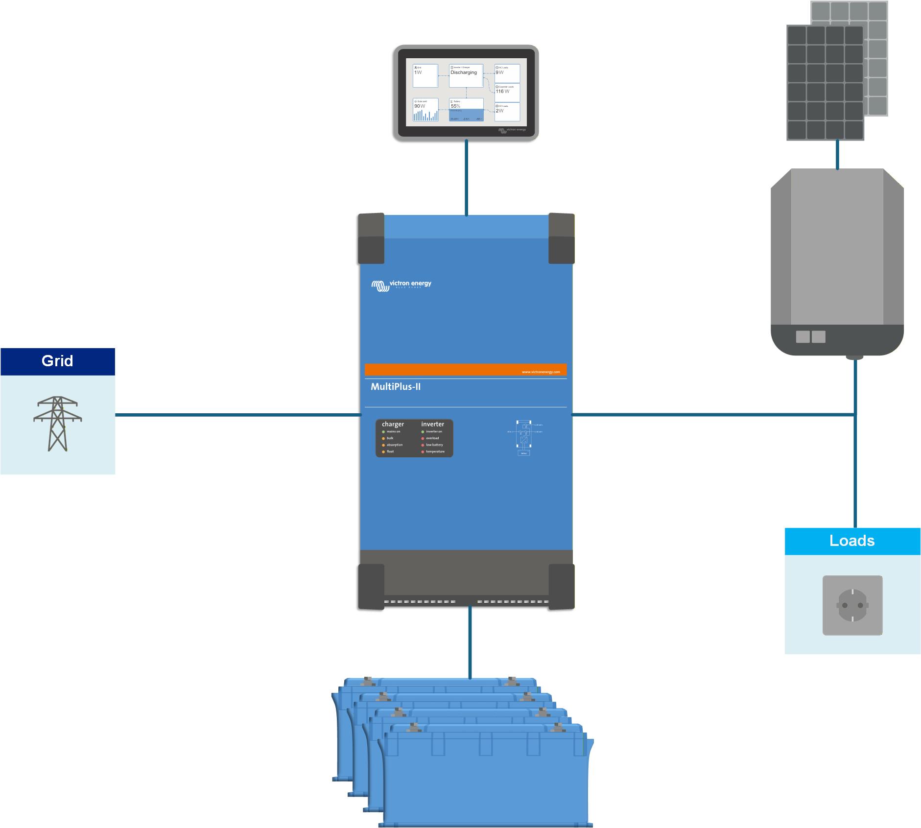
All loads on the output (no grid meter) All loads and PV inverters connect to the AC-Out of the inverter/charger (MultiPlus or Quattro). When the grid is lost, all loads can be backed up by the battery. The grid-tie inverter feeds the microgrid created by the inverter/charger . |
|
Grid-parallel (grid meter required) Loads or PV inverters are also connected on the AC-In side. When the grid is lost, only the loads on the AC-Out can be backed up by the battery. The grid-tie inverter on the AC-In will not work until the grid is restored. |
|
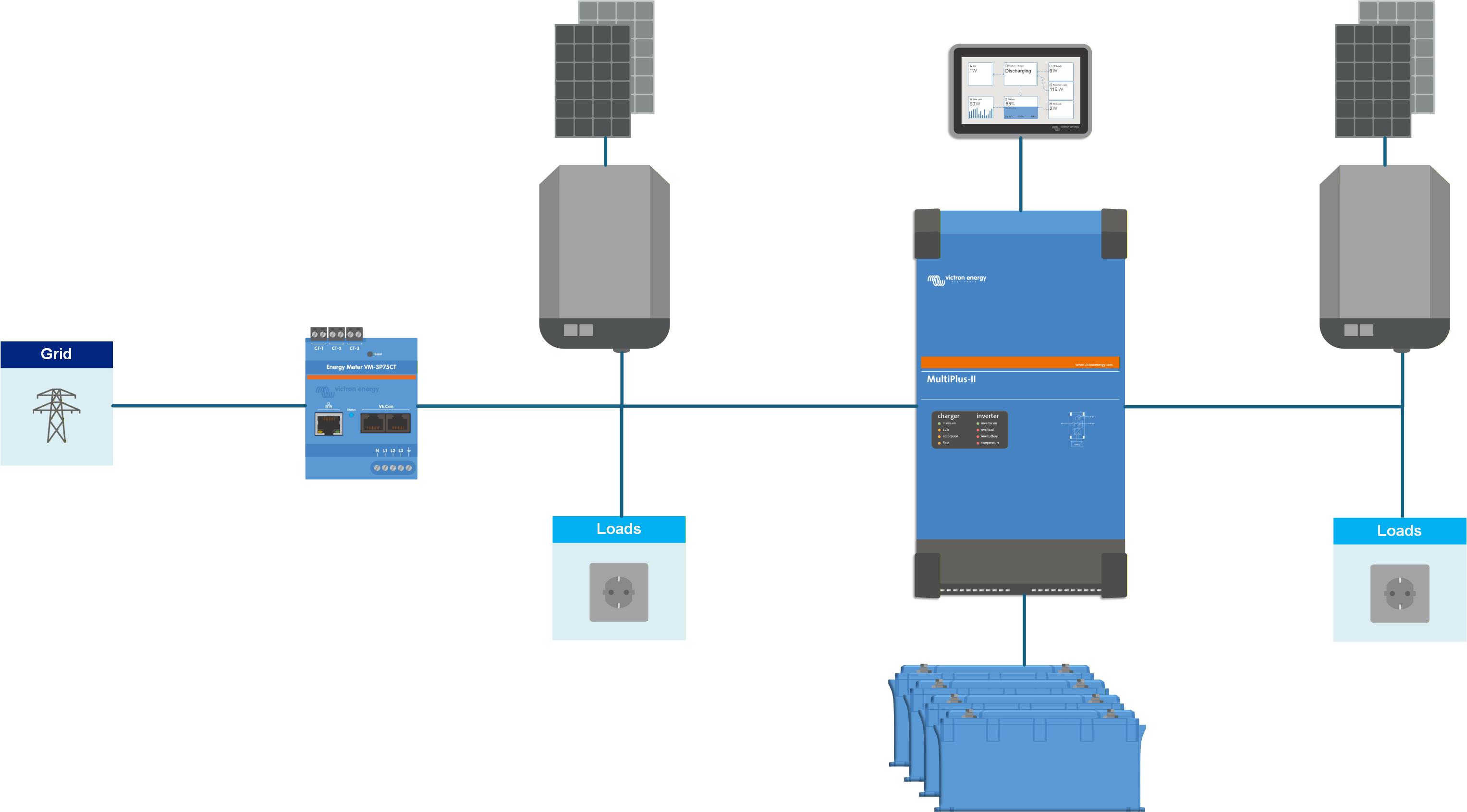
Where a grid meter is required, use a Victron Energy Meter and set it up as described in Configuration.
3.2. Single-phase or multiphase
The system can be set up in different phase configurations, depending on the inverter/charger model:
230V models: single-phase or three-phase.
120V models: single-phase, split-phase, or three-phase.
For details on configuring each, see Multiphase regulation in the Configuration chapter.
3.3. Inverter/charger selection
The required size depends on the type of installation and the appliances that will be powered from the inverter/charger.
DC input voltage range
Choose a model that matches the battery voltage.
AC input voltage and frequency
Choose a model that matches the grid voltage and frequency.
Number of AC inputs
Where a generator is part of the installation, consider an inverter/charger with two independent AC inputs, such as the Quattro.
Maximum AC input current
Inverter/chargers have an adjustable AC input current limit. This value defines how much current the unit draws from AC-In, so select a model whose limit suits the grid connection.
Continuous output power
This is the power the inverter can supply on a continuous basis. The continuous output power varies with temperature. The total power demand of the loads should not exceed this.
Maximum battery charge current
Maximum battery charge current is the highest charge current the unit will push to the battery. When AC-In is available from the grid, a generator, or surplus solar from a grid-tie inverter, the battery is charged at up to this current.
3.4. Battery bank capacity
The size of the battery bank is a trade-off between cost, battery life, and autonomy. It also affects how much benefit can be taken from variable electricity prices.
A smaller battery bank:
is more cost-effective, but the energy used is high relative to its rated capacity.
is charged and discharged at higher C-rates, which can shorten battery life, lead batteries in particular.
A larger battery bank:
combined with a relatively large PV array, can store surplus power on sunny days, keeping power available through several consecutive days of poor weather.
provides longer autonomy during a power outage.
allows more energy to be stored when electricity prices are low and used when prices are high (see Configuration).
Sizing for peak shaving
Where the system is used for peak shaving, the battery and the inverter/charger must together be able to supply the demand above the grid limit for the full duration of the peak. The inverter/charger determines how large a peak can be covered, and the battery how long it can be covered for, so a longer or larger peak requires a larger battery bank. Note that in the Optimized modes only the capacity above the minimum SOC is available for shaving peaks. Further explained in Peak shaving.
For the minimum battery size when a grid-tie PV inverter is connected on the AC output (AC-coupled PV), see the Victron document AC-coupling and the Factor 1.0 rule.
3.5. Connecting PV
The second design decision is how solar is integrated. There are two ways to connect PV to the system, DC-coupled and AC-coupled, and a system can use one or both. The choice affects efficiency, how the system behaves during a grid failure, and, for AC-coupled PV, some sizing rules.
DC-coupled PV
In a DC-coupled system, a SmartSolar or BlueSolar MPPT solar charger connects the PV array to the DC side and charges the battery directly. This is the most efficient path into the battery, because the energy reaches the battery in a single conversion. An MPPT solar charger is up to 99% efficient.
Tip
DC-coupling is the better choice when most energy is consumed outside daylight hours, for example a house where the cooking, laundry and lighting happen in the evening, since the solar energy is stored in the batteries with minimal loss for use later.
AC-coupled PV
In an AC-coupled system, a grid-tie PV inverter connects on the AC side. Its power is used first to supply the loads, then to charge the battery, and any surplus can be exported. Reaching the battery takes two conversions, DC to AC at the PV inverter, then AC to DC at the inverter/charger, with losses of up to 30%.
Tip
AC-coupling is therefore the better choice when most energy is consumed during the day, for example an office running air-conditioning, where the PV powers the loads directly after a single efficient conversion. It also suits large arrays and the retrofitting of an existing grid-tie installation.
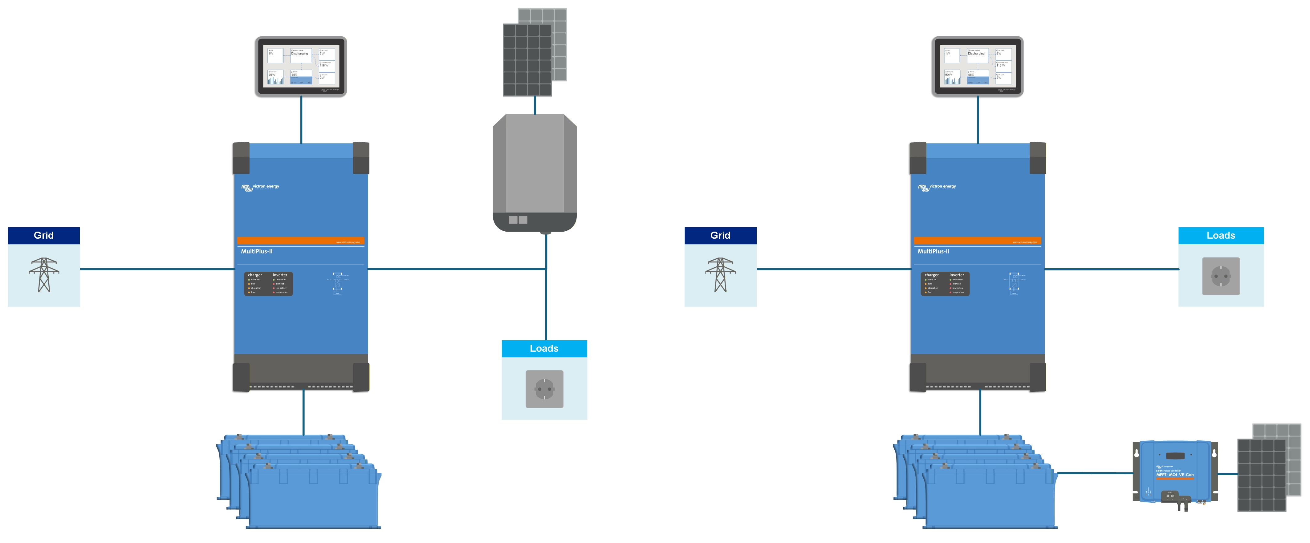 | |
AC-coupled PV feeding the AC-Out side of the MultiPlus-II with a grid-tie inverter | DC-coupled PV directly charging the battery with a SmartSolar MPPT |
Using both
A system can combine DC-coupled and AC-coupled PV, for example DC-coupled MPPT charging on a system that is retrofitted onto an existing AC-coupled array.
Tip
In a backup system that must ride through extended grid failures, always include some DC-coupled PV (an MPPT solar charger), even if most of the PV is AC-coupled. An AC-coupled-only system can reach a deadlock: the grid-tie PV inverter needs the microgrid formed by the inverter/charger in order to run, but if the battery is empty the inverter/charger cannot form that microgrid, so neither can start and the system cannot recover on solar alone. A DC-coupled MPPT solar charger, however, charges the battery directly from PV, with no AC involved, and breaks the deadlock.
Connecting AC-coupled PV: on the input or the output
AC-coupled PV can be connected in one of two places, and the choice changes how it behaves when the grid fails:
On the AC-Out. The PV inverter stays running during a grid failure, because the inverter/charger forms a local microgrid that the PV inverter synchronises to, so solar remains available in a blackout. PV connected here is subject to the factor 1.0 rule, which is further explained below.
On the AC-In (grid side). The PV inverter behaves like an ordinary grid-tied installation. Because this PV sits on the input side, the system needs a grid meter to see it (see Grid arrangement). This PV inverter will not work during a blackout, because there is no grid that it can synchronise to.
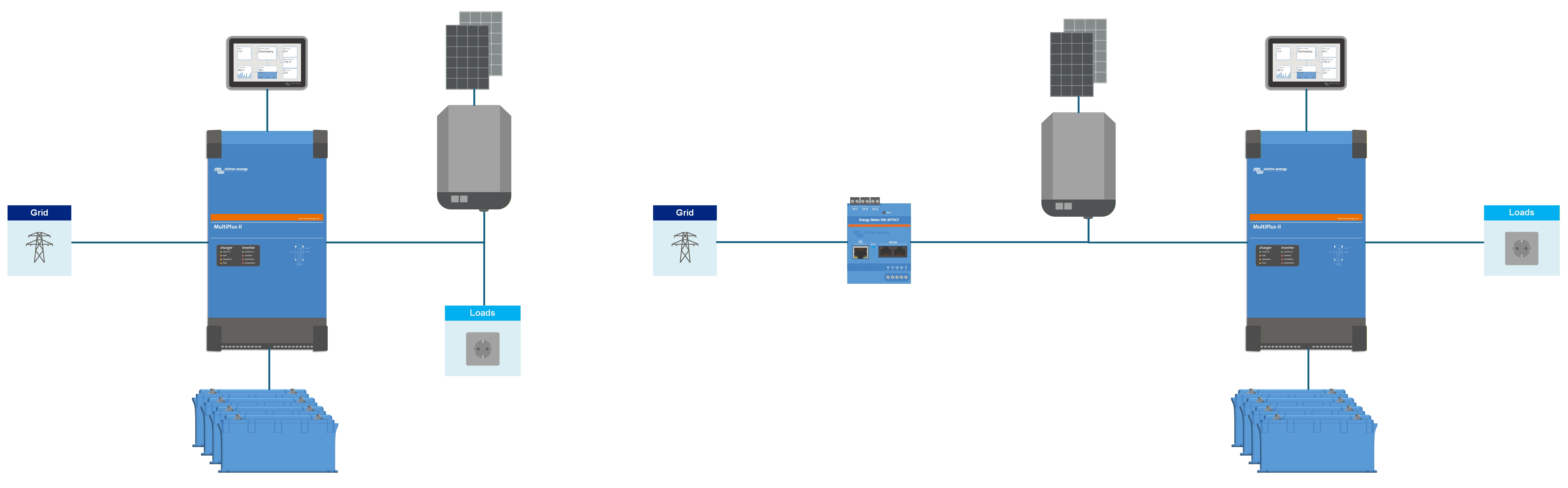 | |
Grid-tie inverter on the AC-Out of the MultiPlus-II | Grid-tie inverter on the AC-In of the MultiPlus-II |
The factor 1.0 rule
For AC-coupled PV connected on the AC-Out, the nominal power of the PV inverter must not exceed the VA rating of the inverter/charger. This is the factor 1.0 rule, a 1:1 limit:
A 3000 VA MultiPlus allows up to 3000 W of PV inverter power.
An 8000 VA Quattro allows up to 8000 W.
Two paralleled 8000 VA Quattros allow up to 16000 W.
Note
Take the lower of the two figures: the PV inverter's nominal AC output power, or the installed array Wp. An oversized array does not raise the limit, because the PV inverter caps what reaches the AC output. An undersized array becomes the limit, because the array caps what the PV inverter can deliver.
The reason is what happens at the moment of a sudden load loss. During a grid failure the inverter/charger forms the microgrid that the PV inverter runs on. If a large load switches off while the PV inverter is at full power, that surplus power has nowhere to go for a brief instant except into the battery, until the inverter/charger throttles the PV inverter by shifting the AC frequency upward. The inverter/charger must be able to absorb that surplus. Keeping PV inverter power at or below the inverter/charger rating guarantees it can. Exceeding it risks a battery voltage spike, a related spike on the AC output that can damage the PV inverter, the inverter/charger and connected loads, and protective shutdowns.
This limit is strict. It applies to all AC-coupled PV on the output, in both grid-connected and off-grid systems, with no exceptions, including in countries where the grid rarely fails, and when a Fronius PV inverter on the AC-Out is used with zero feed-in.
Tip
DC-coupled PV through a Victron MPPT solar charger is not subject to the factor 1.0 rule.
Two related points: AC-coupled PV also has a minimum battery capacity requirement (see Battery bank capacity), and the frequency shifting that enforces this rule is applied automatically by the ESS Assistant (see Configuration). Full background is in the Victron document AC-coupling and the Factor 1.0 rule.
3.6. Feed-in
The third design decision is whether the system feeds surplus solar back to the grid. Whether you can, and whether you should, depends on local regulations, which differ widely from country to country.
Feed-in rules vary by country
Around the world, feed-in is treated in different ways:
Feed-in is rewarded: energy can be sold back to the grid, or used to reduce the bill by running the meter in reverse.
Feed-in is allowed but not rewarded: the utility does not pay for energy fed back, though it remains an ecologically sound contribution.
Feed-in is not tolerated, even for a few seconds: some prepaid meters, for example in South Africa, disconnect from the grid when feed-in is detected.
Feed-in inflates the bill: where the meter counts in one direction only, every kWh fed back is wrongly counted as consumption and charged for.
Confirm the local regulations before enabling feed-in.
With feed-in
DC-coupled PV (an MPPT solar charger): feed-in can be enabled or disabled by a setting on the GX device. When it is disabled, the PV power is still used to supply the AC loads.
AC-coupled PV (a grid-tie inverter): feed-in is set with the AC-coupled PV - feed in excess setting on the GX device (see Grid feed-in). It makes no difference whether the grid-tie inverter is connected on the input or the output side.
No feed-in
DC-coupled PV (an MPPT solar charger): the same GX device setting disables feed-in, and the PV power still supplies the loads.
AC-coupled PV (a grid-tie inverter): Zero or limited feed-in is possible with supported Fronius or ABB grid-tie inverters.
Note
With other brands of grid-tie inverter, the system cannot prevent feed-in.
3.7. Anti-islanding
Anti‑islanding ensures that the system disconnects from the grid and ceases power export upon loss of grid supply, preventing unintentional energisation of isolated network sections. ESS always requires anti-islanding.
Caution
This also applies to systems without feed-in.
For several countries the built-in anti-islanding in Victron products can be used. See certificates on the Victron Energy website for details.
In case there is no certified product available for the country of installation, install an external anti-islanding device.
More details here: VEConfigure: grid codes & loss of mains detection.
3.8. Victron Click & Design
Click & Design is an online tool for building and simulating a 48V system. It estimates how a system would perform in real-life conditions, using actual solar data from the past year. A step-by-step guide covers several stages.
The first step is to locate the system and choose either a Multi RS or a MultiPlus-II with MPPT as the base. Next come the AC input, the priority and non-priority loads, the PV array, and the battery specifications. The tool then simulates system performance hour by hour over a full year, showing how these parameters affect the overall result. Designs are saved automatically and can be reopened later to adjust the parameters, or duplicated to explore and compare different scenarios.
This is not a sizing tool that recommends components. It gives the freedom to design a system and see how well it performs. For example, where a design cannot meet the loads, the tool shows how much energy must come from the grid. The input parameters can then be adjusted to better match performance or budget goals.
With Click & Design it is possible to:
build systems using the Multi RS or MultiPlus-II with split MPPT architecture,
simulate single-phase or three-phase setups,
manage priority loads and optional non-priority loads (in systems with a grid meter),
define the PV array in detail, including orientation and tilt up to 90°, with the full range of Victron MPPT chargers, including MPPT RS (up to 6 MPPT chargers),
add up to six PV inverters for AC-coupled PV, connected on either the AC input or the AC output,
enter custom solar panel parameters instead of choosing a panel from the database,
allow and simulate excess PV export to the grid,
export a detailed PDF report, and
save, edit, and duplicate designs.
Note
For AC-coupled PV, Click & Design uses a generic PV inverter model for the energy calculations. Unlike MPPT solar chargers, the maximum PV voltage and input current are not checked, so the array layout must suit the actual PV inverter used. Warnings are shown where the factor 1.0 rule or the minimum battery capacity is not respected.