2. Installation and configuration
2.1. AC wiring
2.1.1. Configuration options
The configuration option of either Grid Meter, PV Inverter, Generator or AC Meter is set in the GX device. For details on GX device configuration see the GX device configuration chapter. This selection will affect how the system should be wired and how the information received from the meter is displayed on the screen.
See the below diagrams for the different wiring options. Note that wherever the word "Fuse" appears in the diagrams, a 315 mA fuse should be used, if required by local law.
2.1.2. System examples
Example diagrams
 |
EM540 wired as a 3-phase Grid meter
 |
EM540 wired to measure a 3-phase PV Inverter - note that terminals 1, 2 and 3 face the PV inverter
 |
EM540 wired as a single-phase, single-function PV inverter meter to measure a 1-phase PV inverter in a 3-phase system - note that the PV inverter can connect to any of the 3 phases
 |
EM540 wired as a single-phase, single function Grid meter
 |
EM540 wired as a single-phase, dual function Grid meter also metering a PV Inverter on L2
Note
When used to measure a PV Inverter, terminals 1, 2 and 3 should face the PV inverter to ensure correct direction of current and power.
Single-phase, single function
To measure a single-phase PV inverter in a 3-phase system, connect all 3 phases to the grid phasing terminals (4, 5 and 6). Now connect the PV Inverter by wiring the L1 line of the PV inverter to the desired phase (L1, L2 or L3 - terminal 1, 2 or 3).
To measure the grid in a single-phase system, ensure the grid is connected to L1 (terminal 1) of the EM540.
Single-phase, dual function
If you want to use a three-phase meter in a single-phase installation to measure the grid on one input of the meter and the output of the PV inverter on another input of the energy meter, make sure that the energy meter uses L1 and the PV inverter uses L2. See the GX device configuration chapter for more details on how to set it up in a GX device
2.2. Connection to a GX device
2.2.1. Wired connection to a GX device
Connect the EM540 to the GX device using the RS485 to USB interface.
The EM540 is plug and play and its RS485 settings are already configured to the correct parameters for connection to a GX device via the RS485 to USB interface.
The RS485 to USB interface cable between the GX device and the Energy Meter can be extended up to 100 meters; make sure that the extensions of the Data+ (orange) and Data- (yellow) wires form a twisted pair.
The table below shows the colors of the wires and their connection to the terminals of the EM540, as well as the colors to be used for a CAT5 extension cable.
RS485 to USB | RS485 Signal | EM540 terminal number | Suggested wire color CAT5 extension cable |
|---|---|---|---|
Orange | Data + | 8 | Orange |
Yellow | Data - | 9 | Orange/White |
Black | GND | 10 | Brown |
The red, green and brown wire coming out of the RS485 to USB cable are not used. Cut them off or bend them back and isolate them.
 |
EM540 wired connection to a Cerbo GX using the RS485 to USB interface
To ensure signal integrity and robust operation, particularly ensure that:
The extension cabling complies with the minimum cross-sectional area specifications in the RS485 to USB interface data sheet.
The extension cabling has appropriate shielding and twisted pair cores.
The original cable attached to the Victron RS485 USB interface is reduced to a maximum length of 20cm for installations where the total cable length exceeds 10m or where installation/site specific interference occurs - in this case, a suitable/quality cable should be used for the entire cable length and not only for the extension length.
Cabling is installed separated/away from the main DC or AC power cabling.
All wiring is properly terminated (including unused wires) and properly isolated from weather/water ingress.
RS485 networks are traditionally terminated at both ends with 120Ω terminators. This is not required if the cable length is short and you are using the Victron supplied RS485 to USB lengths, but may be required if the cable length is modified.
For detailed wiring/installation notes and specifications refer to the Victron RS485 to USB interface cable ‘Datasheet’.
2.2.2. Zigbee connection to a GX device
The EM540 can also be wirelessly connected to a GX device via our Zigbee to USB converter & Zigbee to RS485.
The Zigbee to USB converter is connected to the GX device and the Zigbee to RS485 converter is connected to the EM540.
Connect the Zigbee to USB converter to the GX device using the supplied USB cable.
A few seconds after connecting, the active LED should be on and the TX/RX LED should be blinking (the converter takes its power from the GX device, so the GX device needs to be switched on as well).
Connect the Zigbee to RS485 converter to the EM540 energy meter according to the table below:
Zigbee to RS485
EM540 terminal number
Color
GND
10
Black
A
8
Orange
B
9
Yellow
In case you have several Zigbee devices installed, make sure only one Zigbee device is powered up right now: the Zigbee to USB converter connected to the GX device. Power down all others. If you don't do this, the Zigbee to RS485 converter may be connected permanently to another Zigbee device.
Connect the 12V DC power supply to the Zigbee to RS485 converter. When the power is switched on, check the LEDs again.
 |
Energy Meter wireless Zigbee connection to a Cerbo GX
Note on old and new Zigbee converters
Please note that there is a new Zigbee converter available now, that is not backwards compatible with the old converters. See table below for old versus new part numbers. If you have a non compatible set, please ask your supplier for a correct version.
old/new | Victron part number | Zigbee to RS485 converter part number |
|---|---|---|
old | ASS300400100 | DRF2619C |
old | ASS300400100 | DRF2618A |
new | ASS300420100 | DRF2659C |
new | ASS300420200 | DRF2658C |
Note on GX firmware versions
For the new type Zigbee converters, Venus OS v2.54 is the minimum required software version.
2.3. GX device configuration
After proper connection and powering up, the meter(s) will be visible on the GX device in the Settings → Energy meters menu:
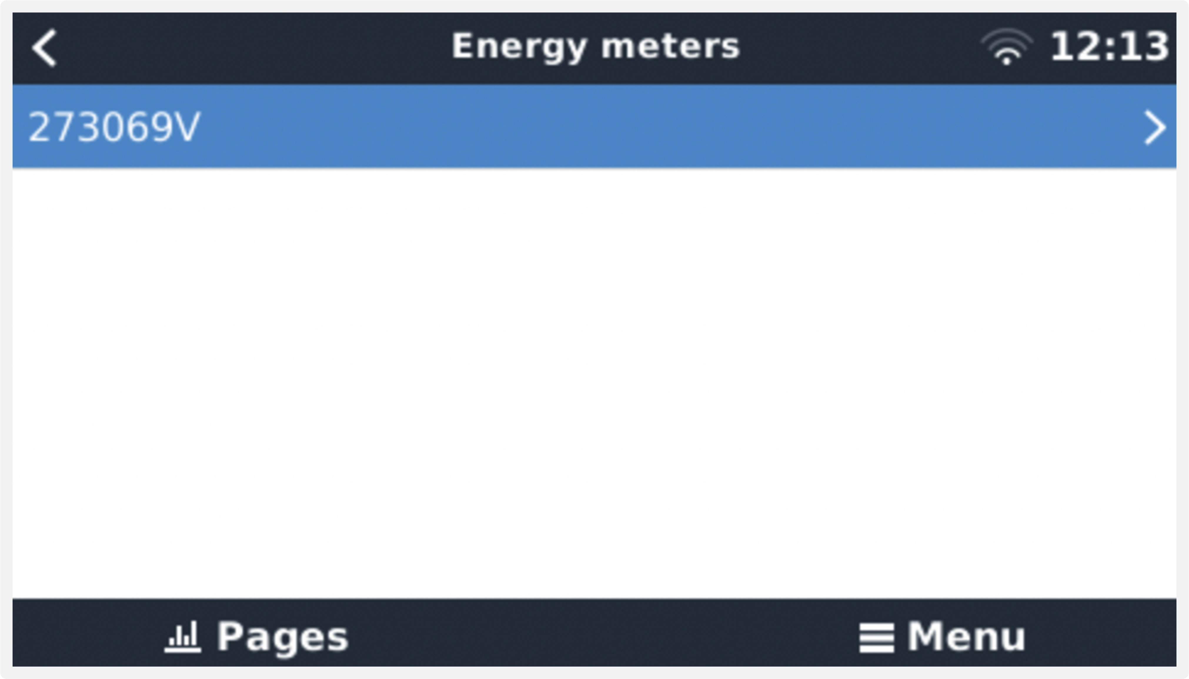 Single Energy Meter in the Energy meters menu | 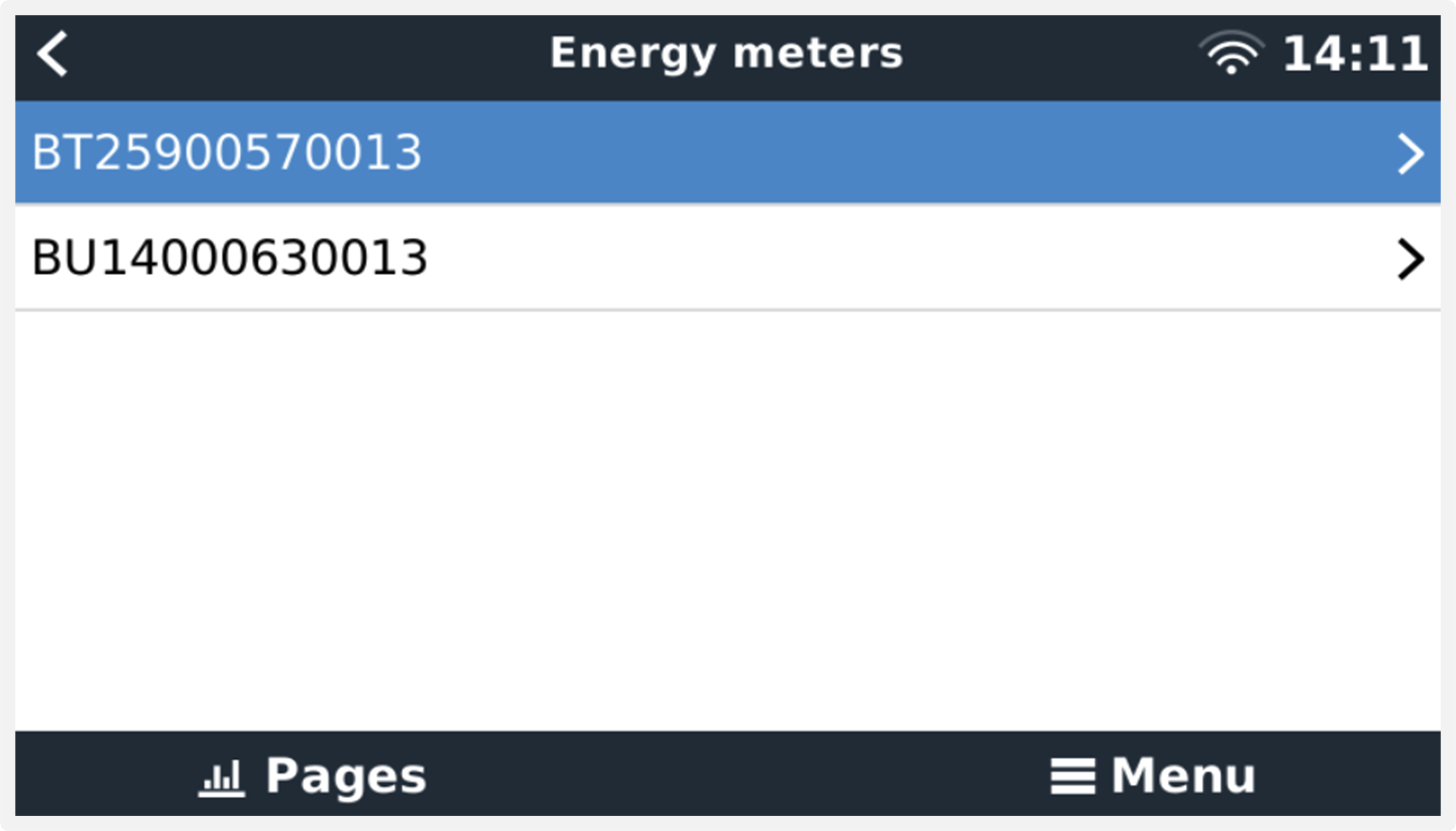 Two Energy Meters in the Energy meters menu |
After selecting an Energy Meter, you have to set the Role and Phase type. Press the space bar or right click to get to the Phase type and Role menu:
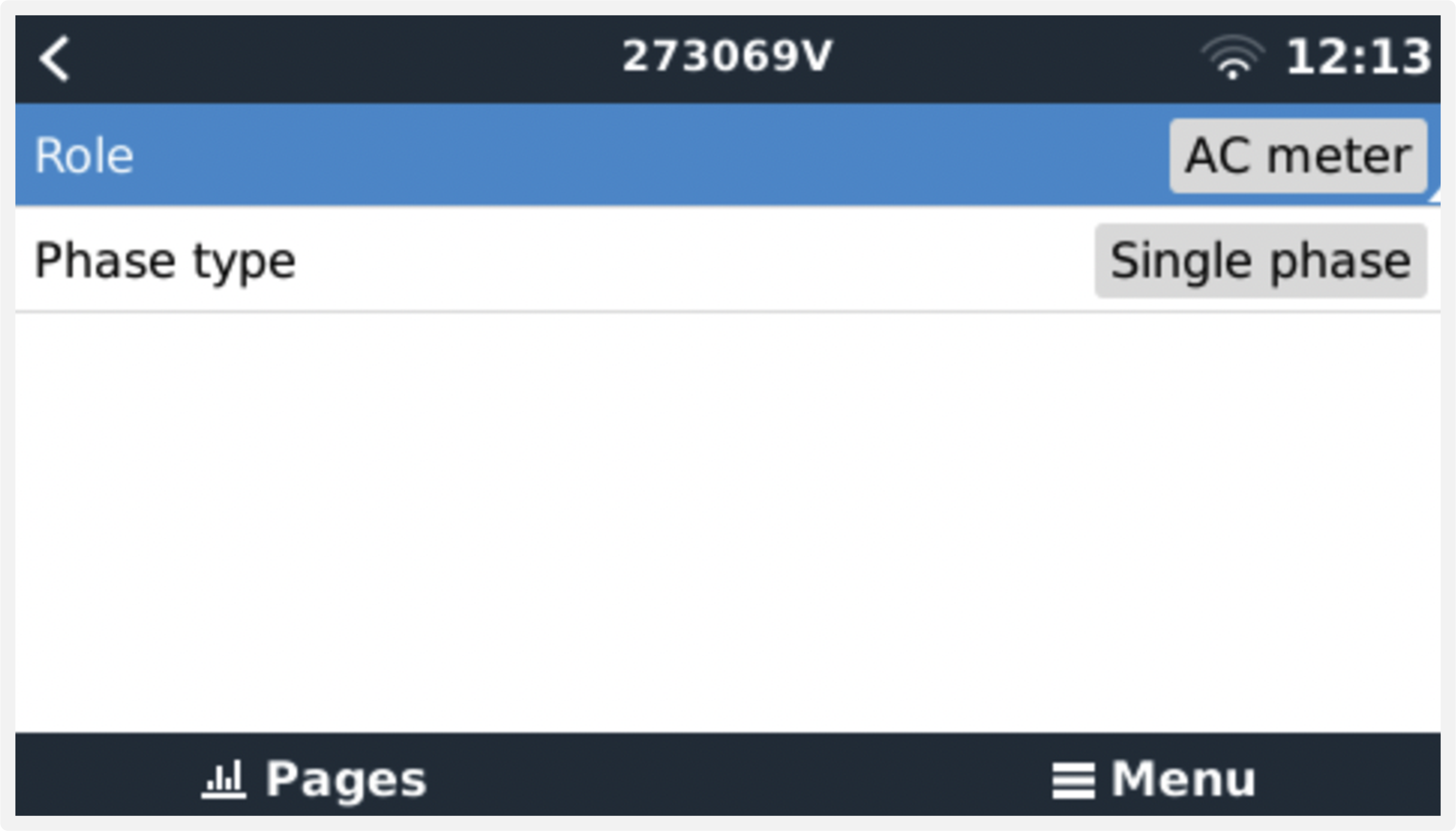 For the ET112 only Single phase option is displayed | 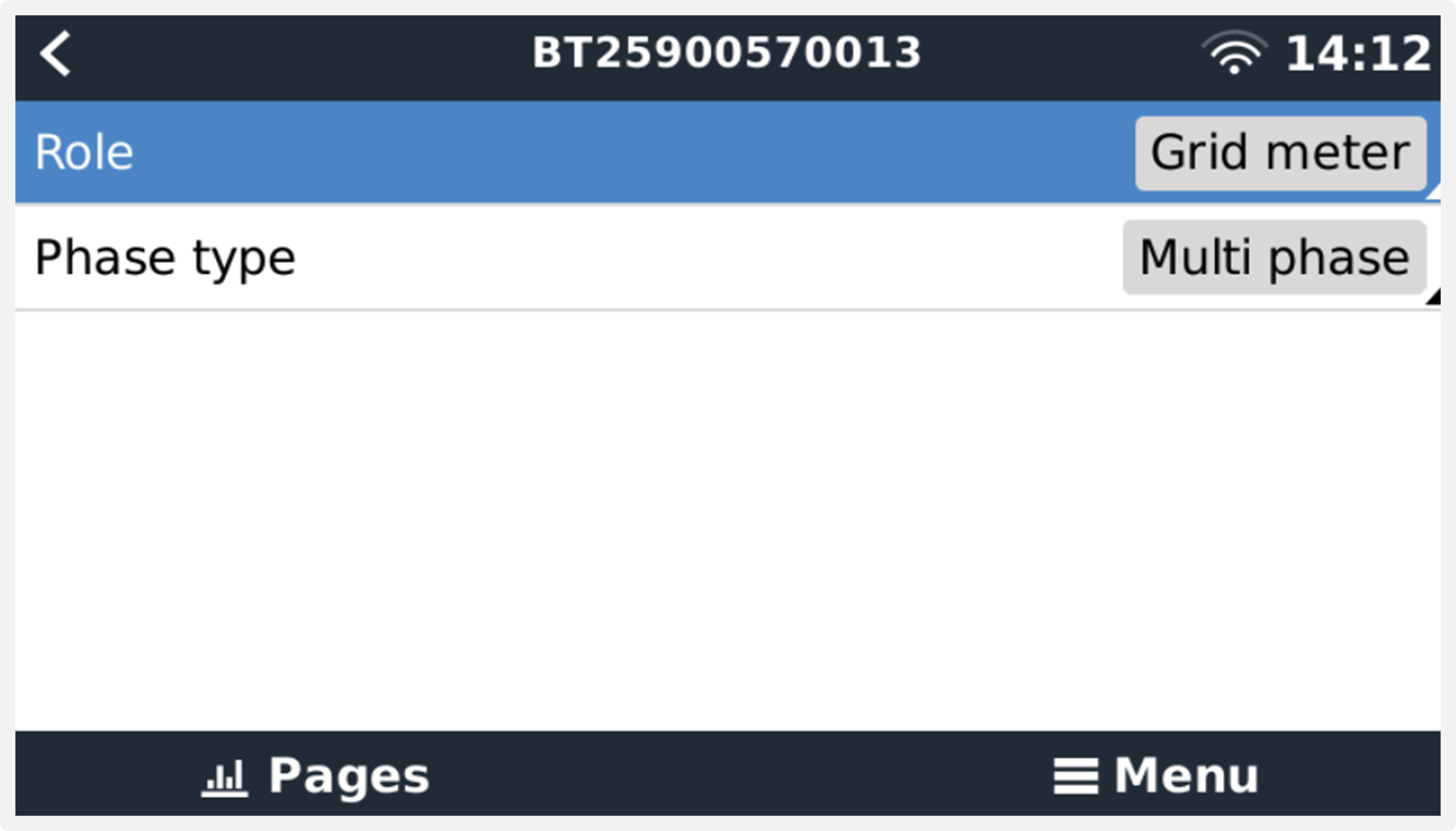 Depending on the application, the role is set here |
Select either Role or Phase type and press the space bar to make changes:
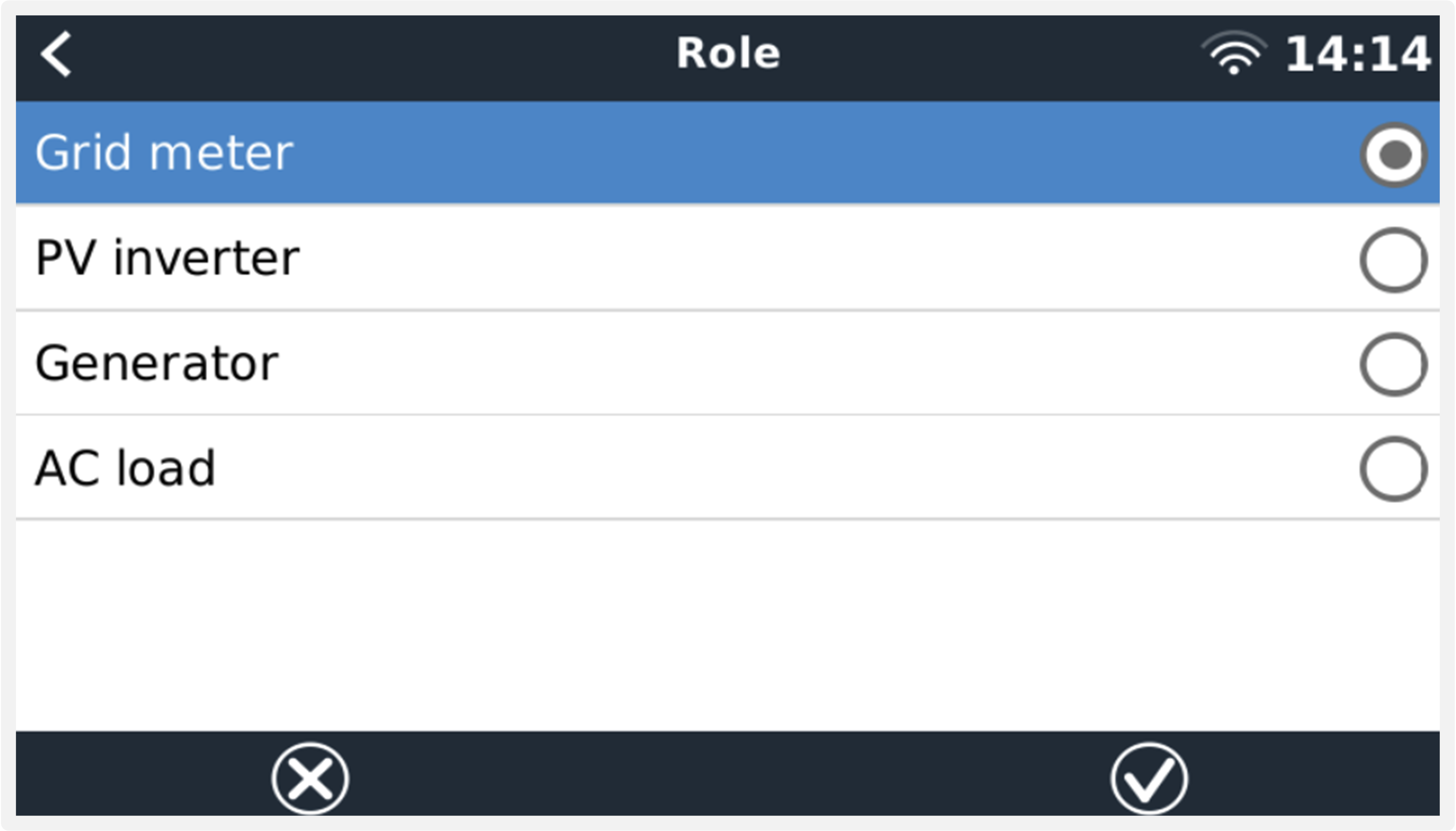 Select the Role according to the application | 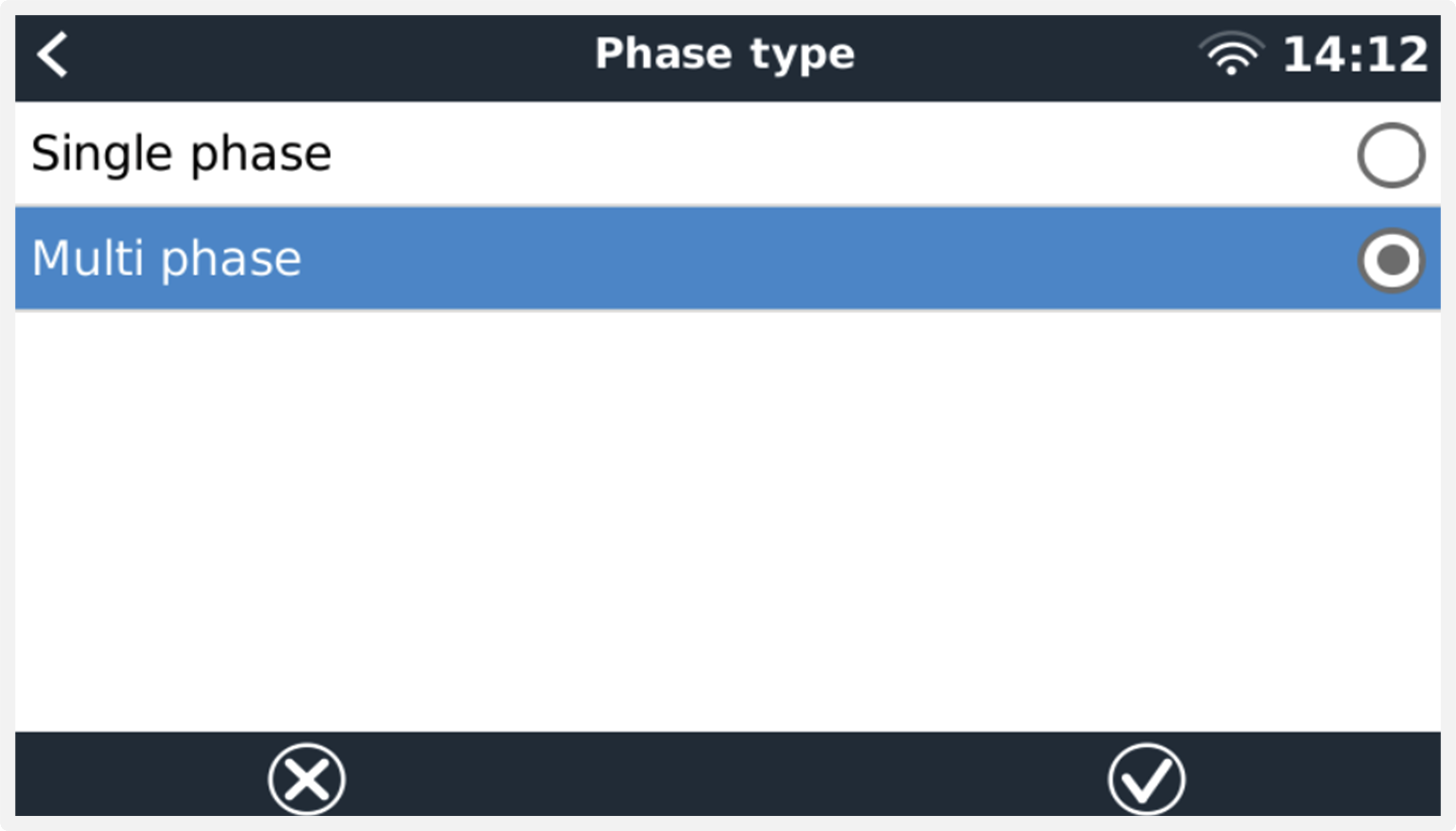 Selection menu for Single and Multi phase type |
Single-phase, single function and single-phase, dual function mode setup:
 Single-phase, single function |  Single-phase, dual function to measure grid on L1 and a PV Inverter on L2. Note that this only applies to the EM540 and ET340. |
After all settings have been made, the Energy Meter now appears with the relevant data in the device list of the GX device:
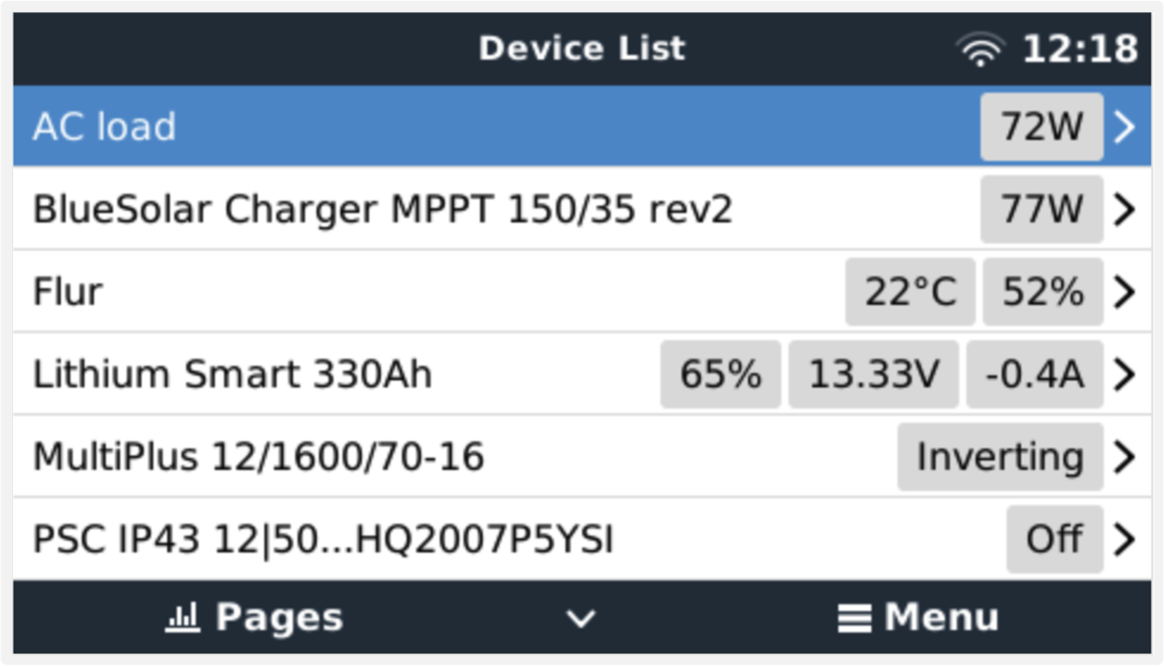 Energy meter set to measure AC loads on the AC output of the inverter/charger | 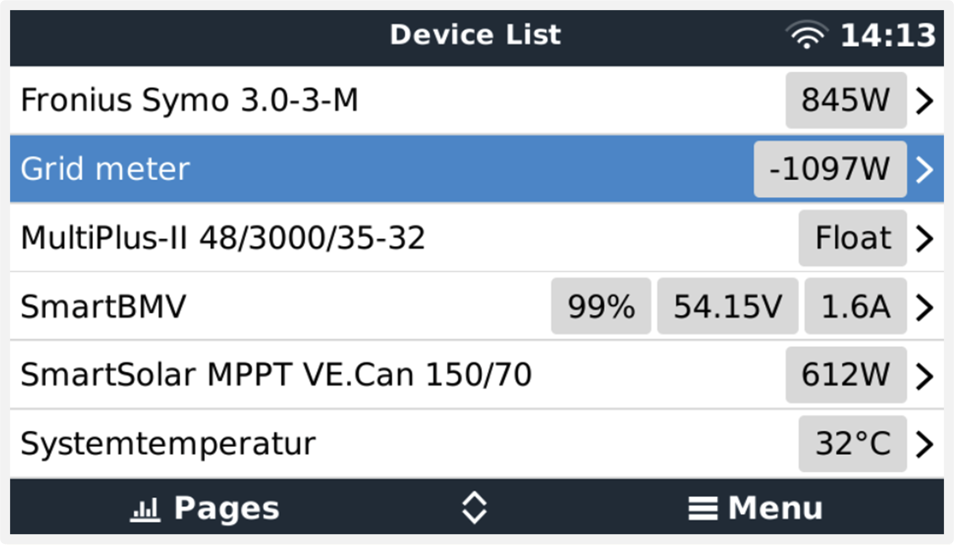 Or configured to measure energy consumption from the grid |
Right-click or press the spacebar to get to the Energy Meter overview with all relevant data on energy consumption and its generation in all phases. At the bottom of the menu, the role of the Energy Meter can be set via the Setup menu. The data used for communication can be read out via the Device menu. You can also set up a custom name for the Energy Meter there:
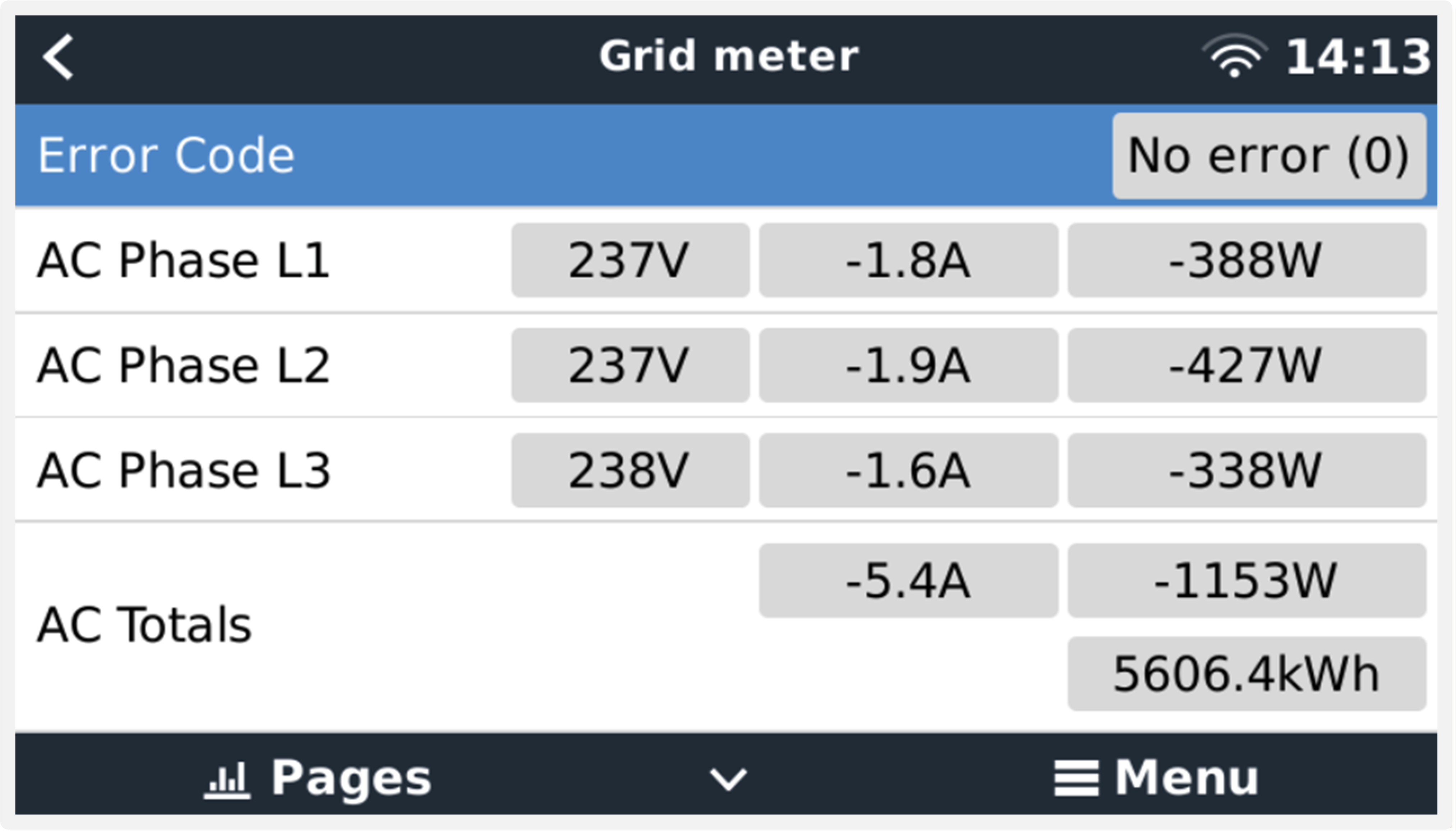 Detailed overview page of a 3-phase Grid meter | 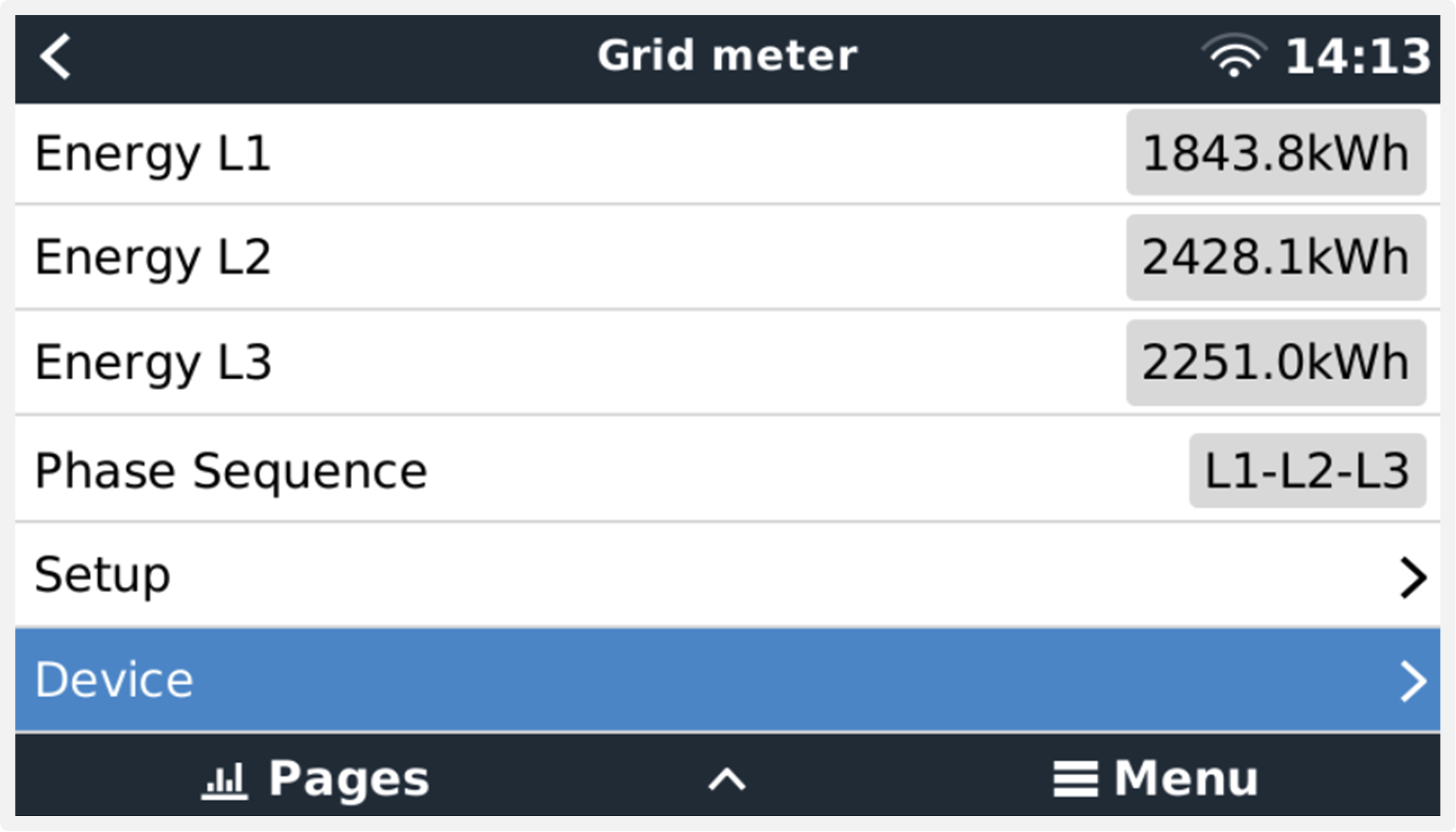 Always be informed about all details, to the second |
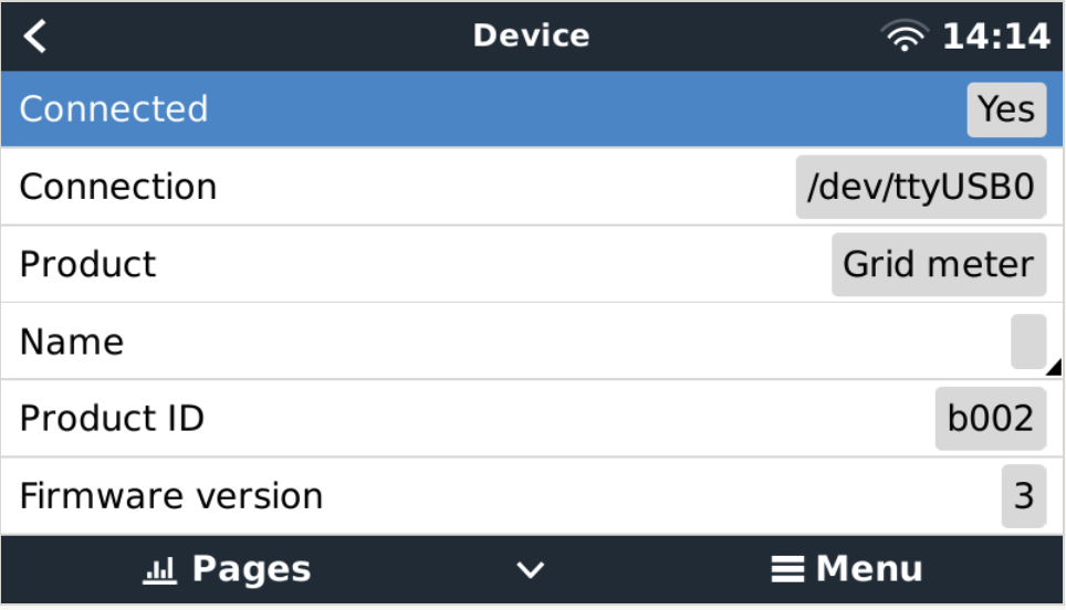 Custom name configuration | 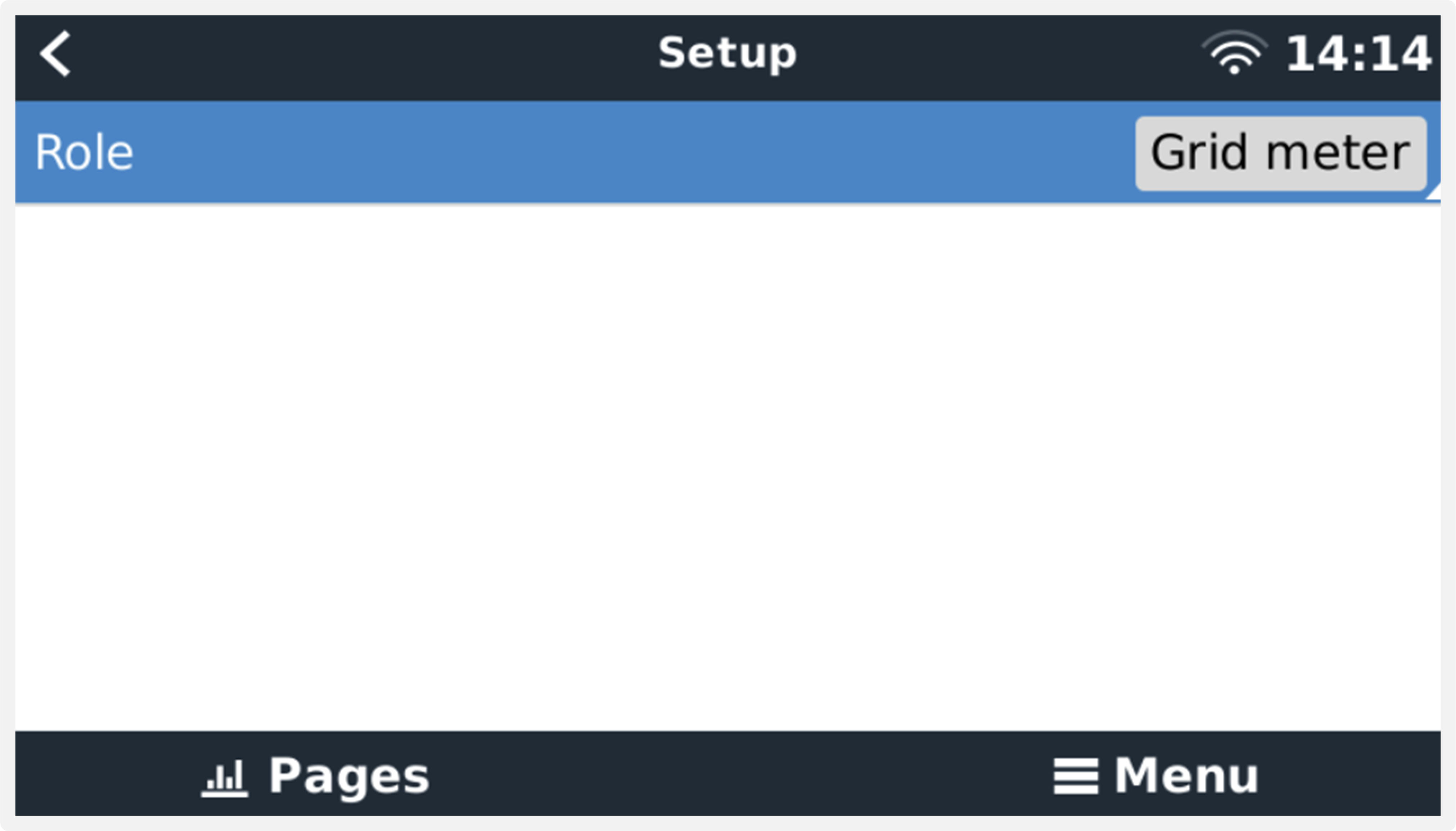 Quickly change roles |
2.4. Multiple Energy Meters in one system
To connect multiple Energy Meters, wire each meter to a separate RS485 to USB interface, which are then each plugged into a separate USB socket on the GX device.
There are 3 options to connect multiple Energy Meters:
Each wired to a separate RS485 to USB interface, which are then each plugged into a separate USB socket on the GX device.
Two Energy Meters wired on to one RS485 to USB interface. In this case the modbus address of the additional meter needs to be changed, so each is unique. See next chapter Changing the modbus address.
Wireless connection: the additional meter is connected to an additional Zigbee to RS485 converter. There is then no second Zigbee to USB converter required. It is then necessary to change the modbus address of one of the AC sensors. See chapter Changing the modbus address.
Besides adding an additional sensor, in a single-phase installation it is also possible to use the unused second phase to measure the power of the PV inverter. See the AC Wiring chapter in this manual.
2.4.1. Changing the modbus address
Press the small button once on the EM540 to enter the 'Setting' page.
Briefly press the small key again to enter the 'System' menu.
Press the down key as many times as necessary to get to the 'RS485' menu.
In the 'RS485' menu, press the small button once to enter the 'Address' menu.
Use the up or down button to change the address to 2 for the additional EM540.
Press the small button as many times as necessary until the display shows 'RS485' again.
Scroll through the menus using the down button until it shows 'End'.
Press the small button once to get back to the 'Setting' page.
Press the left button once. It should now display 'back'.
Press the small button once to return to the overview page.
Note
Only one extra Energy Meter can be added: the system works only with address 1 (the default) and 2.