3. Installation
3.1. Installation Considerations
Ensure that the Autotransformer is used under the correct operating conditions. Never operate it in a wet or dusty environment. The AT is rated to IP21.
Ensure that there is always sufficient free space around the product for ventilation (10cm or 4 inches), and that ventilation openings are not blocked. See specification table for dimensions in Section 4.
Install the product in a heatproof environment. Ensure therefore that there are no chemicals, plastic parts, curtains or other textiles, etc. in the immediate vicinity of the equipment.
3.2. Mounting
Using a level if needed, install the wall hanger in the desired position with provided fasteners. Place AT on to wall hanger and pull down to achieve a snug fit. Install fasteners in the 2 holes provided at the lower portion of the enclosure.
The AT can be mounted in any orientation. Note that the Vertical position is the optimal orientation because it has maximum heat dissipation and easy access the terminal board.
3.3. Wiring
The Autotransformer has several possible configuration options and must therefore be installed correctly for the desired outcome. The terminal block may be used as an input for certain applications, and in other applications the terminal block is used as output.
Remove cover by removing 4 fasteners found in all four corners. Carefully remove front cover keeping in mind the 3 LED status lights.
See diagrams in Sections 2.3.1 through 2.3.4 for the placement of conductors that correspond with the desired configuration.
3.4. Conduit
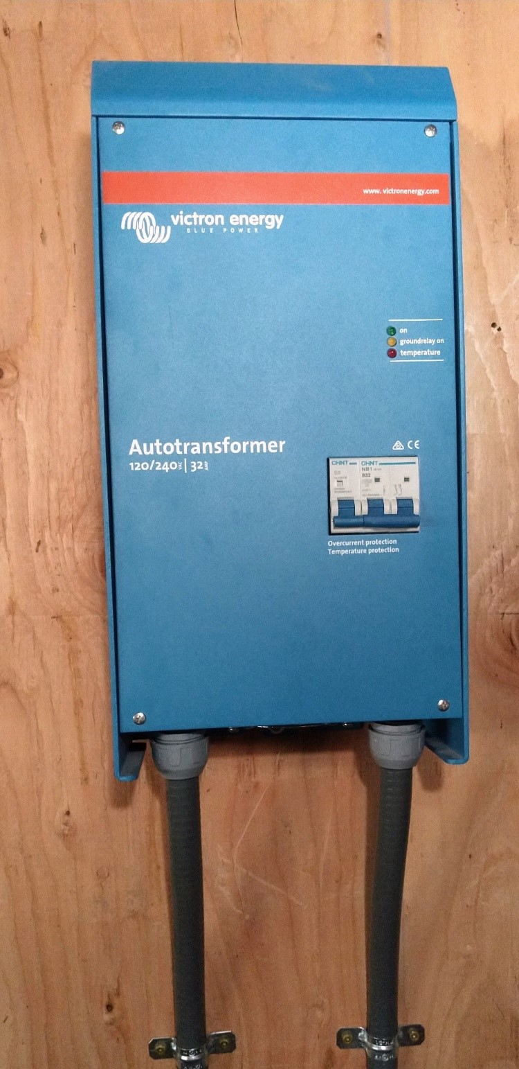
Both models of the AT can be fitted with conduit if required. For the 32A model remove supplied cable glands/strain relief and replace with 1/2” (.5 inch) or ¾” (.75 inch) NPT (National Pipe Thread) conduit fittings. See illustration below. The 100A model will require lager conduit fittings.
 |