 Add this page to your book
  Remove this page from your book
  Manage book (
 Help
Help Table of Contents
ECOmulti installation Hub-2
— Andreas Kriwanek 2014/11/09 10:44 —
This document shows my practical experience in installing my first ECOmulti as a Hub2 system. The following program and firmware versions are used:
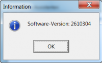
| VEConfigure 3 Rev. 90.04.169 ECOmulti firmware 2610304 Color Control GX rev. 1.14 |
Scenario
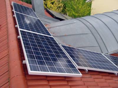
A new photovoltaic system with storage needs to be installed on a house. There is little room on the roof, so only a maximum of 12 solar modules can be installed. A few trees, a chimney and a dormer window will create partial shading on the modules. The shading will degrade the overall performance if a normal string inverter for all modules were to be used. The solution is to use 12 micro inverters (Sunny Boy 240) which are to be installed to enable individual MPPT tracking for each module. The micro inverters generate 230VAC at their paralleled output, which is fed into one phase of the houses mains supply. For self-consumption and storage a Victron ECOmulti is to be used on the same phase. It is designed as a Hub2 installation, where the photovoltaic energy is applied on the ECOmulti's AC output.

The system design follows the golden rule that generated solar energy has to be equal to the storage batteries and the power of the ECOmulti:
- 12 x solar modules 240Wp with 12 x micro inverters; 2,88 kWp
- 2 x LiFePo-BMS batteries 90Ah: 2,4 kWh
- Maximum power of the ECOmulti: 3,0 kW
Bill of Materials (BOM)
For this solar plant the following parts are needed:
- 1 x Victron ECOmulti 24/3000/70-50, Part# EMP243020100
- 2 x Lithium battery 12,8V/90Ah - BMS, Part# BAT512900400
- 1 x Victron AC current sensor, Part# CSE000100000
- 1 x Victron MEGA-fuse 300A/32V (package of 5pcs), Part# CIP136300000
- 1 x Interface MK2-USB (VE.Bus to USB), Part# ASS030130000
The fuses are spares.
Components of the ECOmulti
At the moment, there is no manual for the ECOmulti available in the download area (Only the datasheet). But that is fine, as the ECOmulti consists of well known Victron components in one smart housing:
- Inverter/charger MultiPlus 24/3000/70-50
- Battery Management System VE.Bus BMS
- Color Control GX (CCGX)
- Fuse holder for MEGA-fuse with a MEGA-fuse 300A 32V
- Complete cabling of all components, including battery cables
There is enough space in the housing to install two Lithium battery 12,8V/90Ah with BMS. The advantage of the ECOmulti is, that all of the components are cabled and checked in the factory. Unpack, mount it to the wall, connect the 230V system and start the ECOmulti. This saves precious time at a customer's site.
The components are cabled in this way:
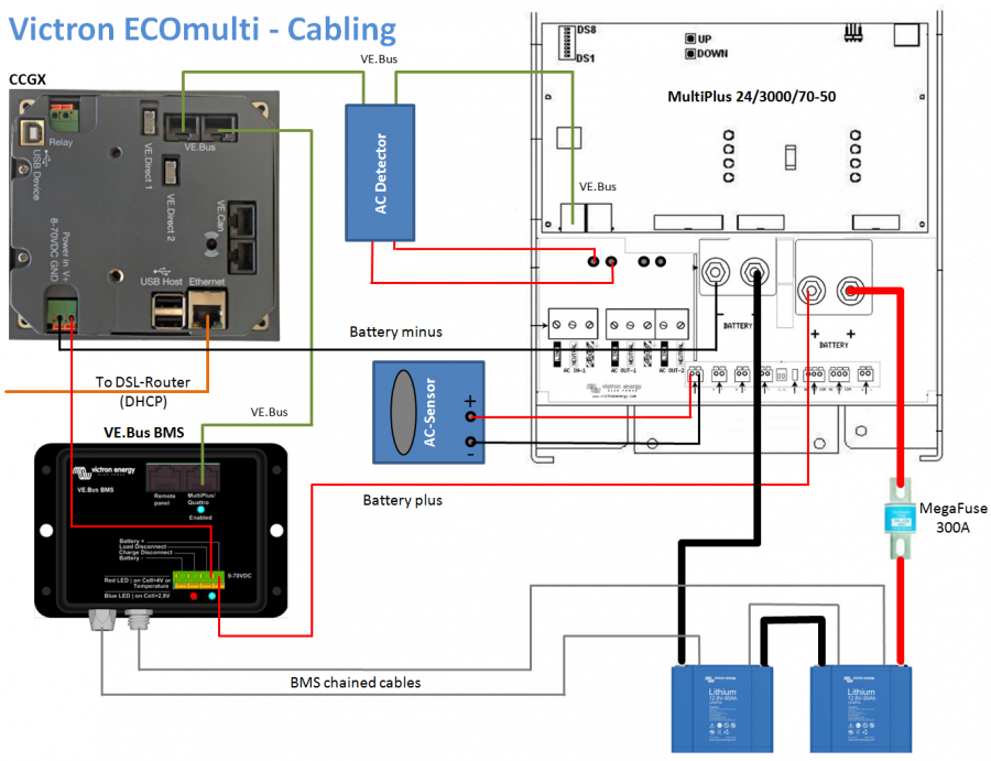
In the following sections the installation of this system is documented.
Mounting the ECOmulti
- Choose installation area: The CCGX should be 170cm above the floor so that your customer can look directly at the display. This will also prevent damage to the ECOmulti in case of any water flooding into the basement
- Consider that there is enough space around the ECOmulti for good ventilation
- Use a hammer drill to make four 8mm holes and insert the dowels
- Mount the ECOmulti wall plate with the supplied screws
- Check that the mounting plate is affixed well. The ECOmulti has a weight of approximately 60 kg!
- Hinge the ECOmulti onto the wall plate
- Mount a cable funnel between the ECOmulti and the distribution box
Connecting to mains
An analysis of the customer's side, showed that the phase where the most nightly load is drawn is phase L2. The ECOmulti must be placed on this phase to provide the best usage of the batteries. In Germany there is a grid which provides three phases L1, L2, L3 together with the neutral line N. In the junction box there are three electronic main fuses F1/F2/F3/35A (this can differ from house to house, up to 3x 63A). L2 from the fuse will be connected to the ECOmulti input, L2 from the houses is connected to the ECOmulti output. A transfer switch S1 with 35A is installed between input and output to close the phase L2 in case of a ECOmulti failure. In normal operation this switch has to be open!
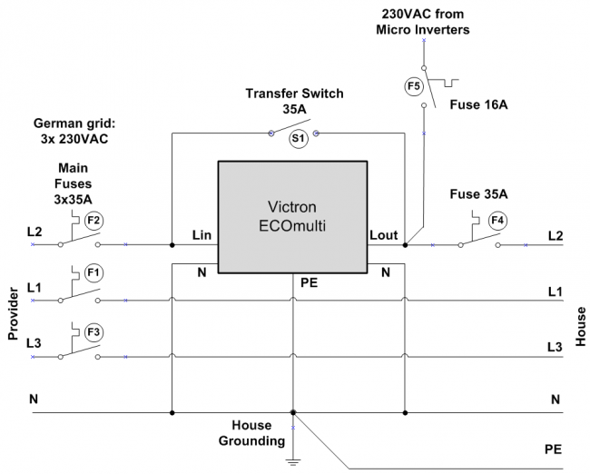
The photovoltaic energy (in this case 230VAC/12A from micro inverters) will be fed into the house L2 phase on the output of the ECOmulti (=Hub2). An extra fuse F5/16A is protecting the solar system.
On the L2 output of the ECOmulti another electronic fuse 35A is mounted to prevent a damaged ECOmulti in case of a short in the house. For maintenance work on the ECOmulti the main fuse L2, the output fuse L2 and the solar fuse 16A can be switched off.
Mounting the AC sensor
The AC sensor is needed for measuring the generated solar energy. The values of the sensor will be displayed on the CCCGX and on the VRM portal. The sensor is not needed for controlling the ECOmulti!
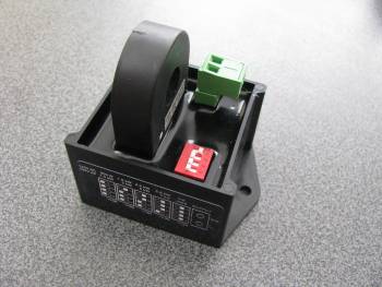
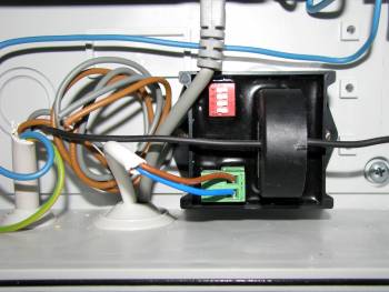
Set the DIP switches on the sensor according to the maximum photovoltaic power of your modules. This plant has a peak value of 2,88kWp, so the switches are set for the 3,000W range. The green connector is polarized +/-. Be sure you don't to swap the wires to the ECOmulti. The AC sensor has to be mounted in the junction box of the inverter. The black wire is the 230VAC phase from the micro inverters. The wire is directed through the hole of the current sensor. Be sure, that you only use the phase. If phase and neutral are both used, their magnetic fields will be subtracted and the display value is zero:
In the above image an installation cable 2 × 0.75mm² is used for connecting the sensor to the ECOmulti. Tests have shown, that a shielded cable doesn't improve the values. An installation cable is enough. The brown wire is plus, the blue wire is minus!
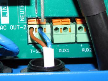
The cable leads to the T-Sense input of the ECOmulti: plus on the left (brown) and minus on the right side (blue). AUX1 and AUX2 can only be used on the newest ECOmultis, the recommendation is to use the T-Sense input. This will work on all ECOmultis.
Mounting the batteries
- Switch off the mains supply for the ECOmulti
- Remove the ECOmulti cover
- Remove the mounting fittings in the battery bays
- Insert the two batteries
- Mount the fittings to secure the batteries in the housing

- Check the voltage of each battery with a multimeter:

- Each of the batteries should have about 13.3VDC:

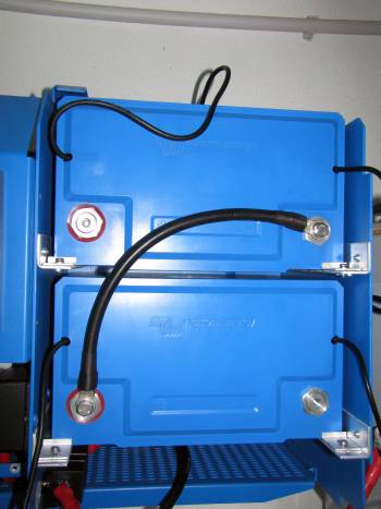
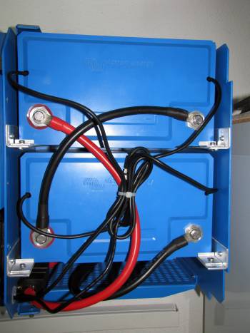
- Mount the interconnection cable (black) between the two batteries:
- Mount the plus cable (red) of the ECOmulti to the first battery:
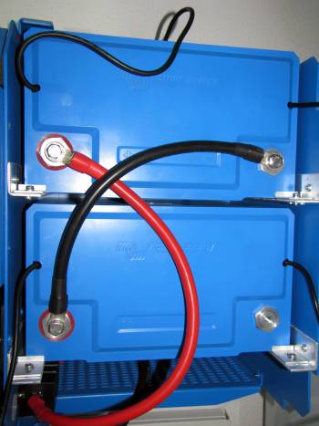
- Mount the minus cable (black) of the ECOmulti to the second battery
Caution: The last step will produce electrical sparks due to the inductance in the ECOmulti! Just proceed, nothing will be destroyed!
Interconnect the BMS cables of the batteries in a chain:
Connect the BMS cables to the VE.Bus BMS in the ECOmulti:
Double check the cabling
Don't believe your electrician! I gave him a circuit diagram where the 230VAC photovoltaic cable has to be connected on the ECOmulti output (= Hub2). After cabling we needed a lot of hours to get the ECOmulti working. Finally we found out, that the electrician had cabled the photovoltaic output to the input of the ECOmulti (= Hub1). To save you a lot of hours of bug fixing, an accurate check of all cables is recommended.
Prepare your laptop for installation
Required hardware for installation/configuration:
- Laptop with Microsoft Windows operating system
- Interface MK2-USB (VE.Bus to USB)
- RJ12 UTP Cable 3 m (or even longer)
Download the required Victron software from Victron https://www.victronenergy.com/support-and-downloads/software:
- VE Configuration tools for VE.Bus Products
This package includes the utilities “VEConfigure 3” for configuring the ECOmulti and “VEFlash” for flashing the firmware. After installing, start the utilities with a working internet connection. The software will check for updates automatically.
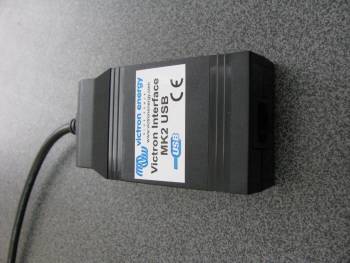
The MK2USB interfcae.
Check for a possible firmware upgrade
The ECOmulti will be delivered in most cases with the new micro. Check this by searching for the label on the mainboard:
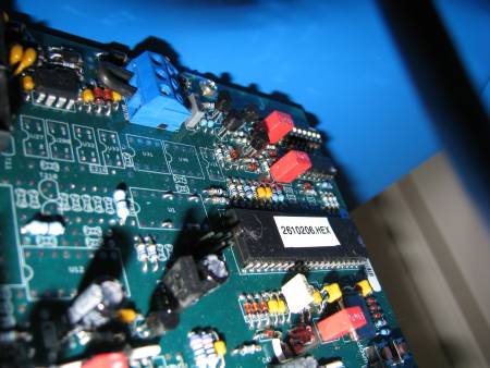
In this case the label is “2610206.HEX”.
On this mainboard the new micro is installed. If you want to use the Hub2V3 assistant, you have to flash a new firmware.
For this ECOmulti, there is a newer firmware “2610304.HEX” available. You can get it by email from Victron. Note down your old firmware version when checking compatibilty of the new firmware.
Flashing firmware to ECOmulti
Best practice:
- Get firmware from Victron via email
- Disconnect grid and load from ECOmulti (using the two 230VAC main switches)!
- Disconnect the VE.Bus cable of the CCGX from the mainboard
- Connect the Interface MK2-USB with the UTP cable to the ECOmulti mainboard
- Connect Interface MK2-USB with the USB cable to a free USB connector on your laptop (USB2.0 or 3.0)
Leaving the CCGX VE.Bus cable plugged in can lead to programming problems. Be sure to remove the connection of the CCGX whilst flashing the firmware.
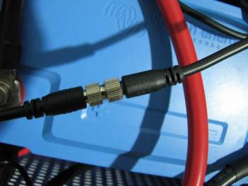
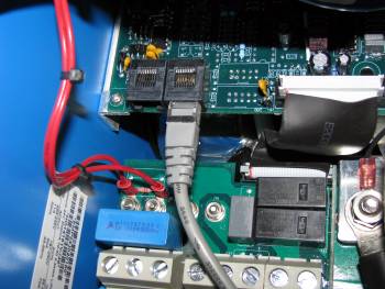
Cabling for CCGX connected to ECOmulti (blue cable):

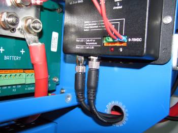
Cabling for MK2USB connected to ECOmulti (grey cable):
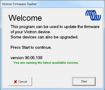
Start the VEFlash utility on the laptop, then click “Start”
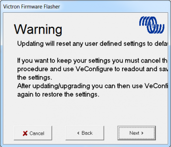
All actual settings of your ECOmulti will be deleted! Be sure you have saved it in a file and click “Next”:
To Victron : I am using a Windows7/64Bit laptop with a display resolution of 1920x1080px. The text lines are cut on the right side of the window. Maybe you are using a fixed size font? Can you fix this?
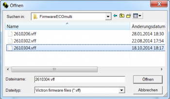
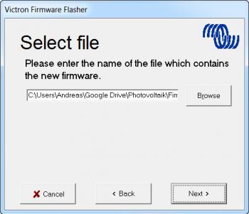
Select the new firmware file from a directory on your laptop:
Click “Next” to load the firmware:
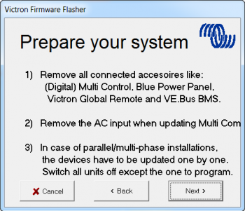
Last chance to disconnect 230VAC from the ECOmulti input. The VE.Bus cable of the CCGX must also be disconnected. Click “Next”:
Select the COM port of the MK2-USB from the list or click “Auto detect comport”. Then click “Next”:

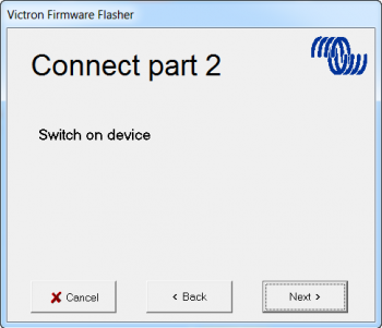
Switch off the mainboard of the ECOmulti, then click “Next”:
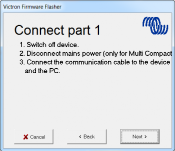
After a few seconds switch on the mainboard again. Click “Next”:
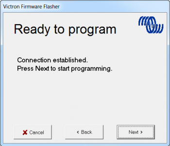
To start flashing the firmware, click “Next”:
Flashing is active now:
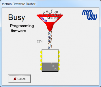
After 1 minute the mainboard is flashed completely. Click “OK” to terminate VEFlash now:

Remove the UTP cable of the MK2-USB and connect the VE.Bus cable of the CCGX to the mainboard instead. Connect grid and load to ECOmulti (using the two 230VAC main switches).
Configure the ECOmulti with VEConfigure3
Best practice:
- Disconnect the VE.Bus cable of the CCGX from the mainboard
- Connect the Interface MK2-USB with the UTP cable to the ECOmulti mainboard
- Connect Interface MK2-USB with the USB cable to a free USB connector on your laptop (USB2.0 or 3.0)
- Start the VEConfigure3 utility on the laptop and wait for a USB connection
Configure the ECOmulti with the following parameters:
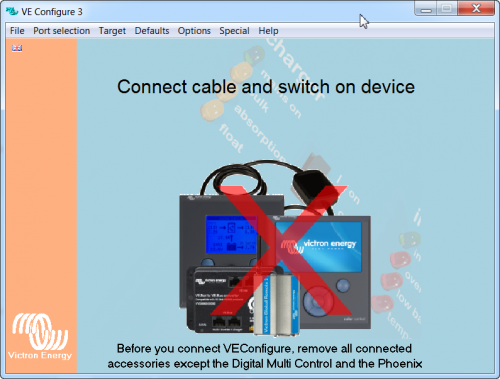
Selecting the right com port:

Selecting the right port will start the receiving of the ECOmulti parameters:

The assistant configuration will be fetched now:

Select the register “General” and set your parameters:
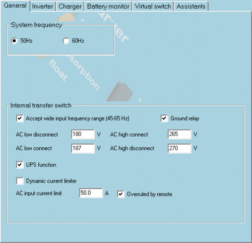
- In Europe select a system frequency of 50Hz
- Select a “Wide input frequency range” for using SMA SunnyBoy 240.
- Select “Ground relay” for safety
- Choose “UPS” Function. This makes the ECOmulti to a micro grid
Switch to the next register tab “Inverter”:
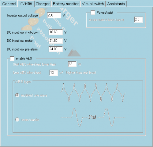
- Deselect Power Assist
- Deselect Aktivierung AES
Switch to the next register tab “Charger”:
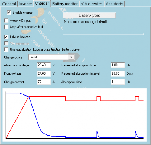
- Activate charger
- Choose battery type LiFePo4. The parameters will be set accordingly
Switch to the next register tab “Battery monitor”:
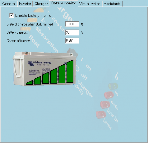
- Activate the battery monitor
- Set the capacity to 90AH
- Increase … to 100% to allow the full load of the batteries
Switch to the next register tab “Virtual Switch”:
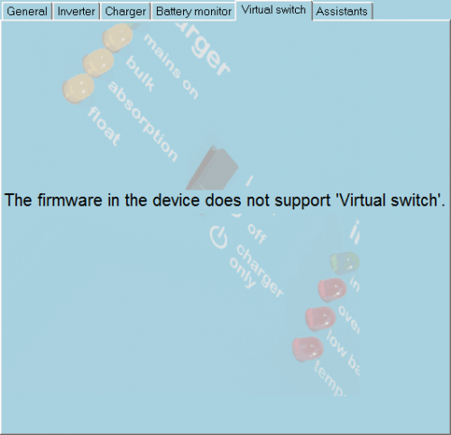
The virtual switch is not supported.
Switch to the next register tab “Assistants”:
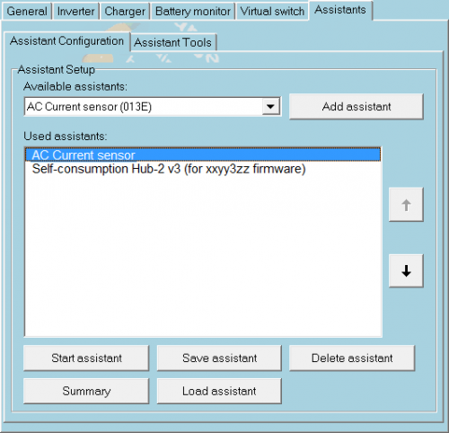
Add the assistant “AC Current sensor” and start configuration by clicking on “Start assistant”:
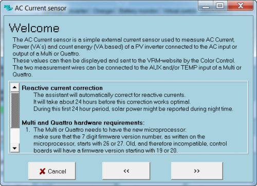
The new feature reactive current correction is displayed. Click “»”:
Select the input on ECOmulti, where the AC sensor is connected. In this case it is temperature input. Click “»”:

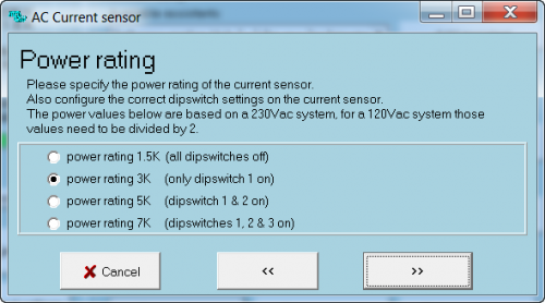
Select the power range of the AC sensor. In this example it is the 3000VA range. Click “»”:
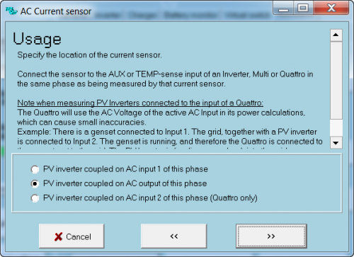
For a Hub2 system, the photovoltaic output must be connected to the ECOmulti output. Select the middle option and click “»”:
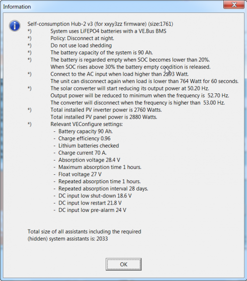
The AC sensor is completely configured. In the register tab “Assistants” add the “Self consumption Hub-2v3”:
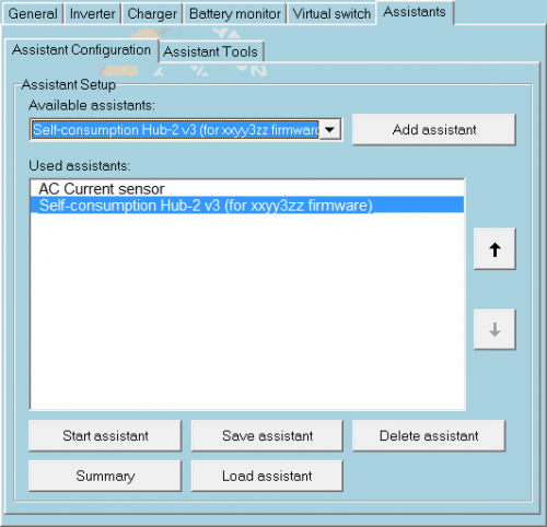
Click “Start assistant” to configure the parameters.
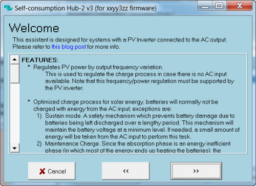
Click “»” to leave the first info screen.
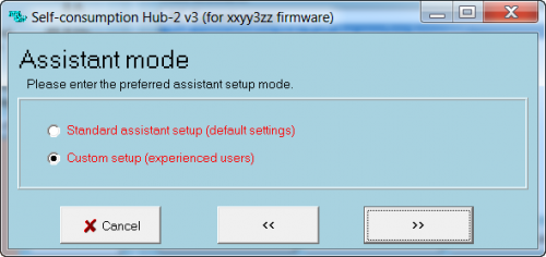
Select the user specific setup and click “»”:
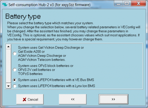
Select LiFePo4 with BMS for the ECOmulti. Click “»”:

Select the option for disconnect at night, then click “»”:

We need none of the options, click “»”:
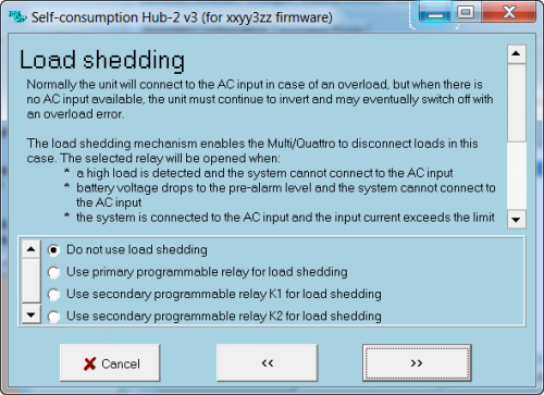
Don't use load shedding. Click “»”:
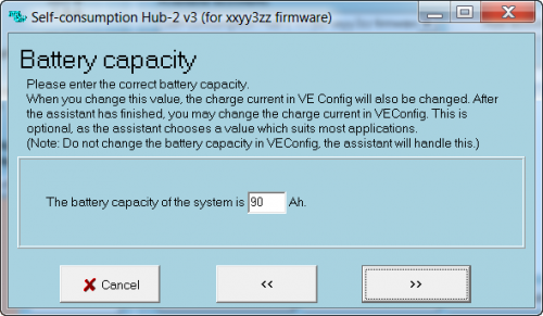
Check battery capacity. It should be 90Ah for the LiFePo4 batteries. Click “»”:

The battery empty levels are already configured correctly, just click “»”:

The displayed values are OK, click “»”:
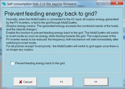
The ECOmulti should feed energy back to the grid, so this option isn't used. Click “»”:
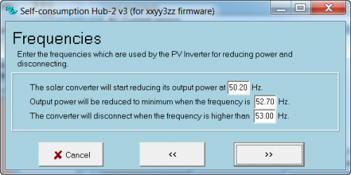
The frequencies are OK, click “»”:
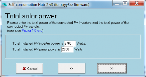
Adjust the values to the photovoltaic energy values of your system, the click “»”:

This screen shows a summary of your settings. Read it carefully and click “»”. The assistant configuration is finished.
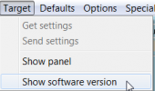
In the program menu select
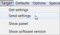
This will send the settings to the ECOmulti.

Send all settings and click “OK”:
Configuration settings will be sent now. After a short time a question is shown:
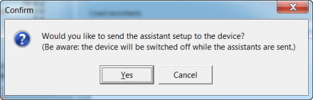
Answer the next question with “Yes” to send all assistant settings to the ECOmulti, too:
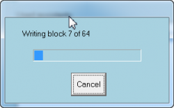
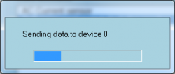
It takes about one minute to send the settings. The ECOmulti output will be switched off during the transmitting.
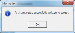
Answer the success message with “OK”.
It's a good idea to save the settings in a file on your laptop. You can use it for another ECOmulti again. In the main menue click

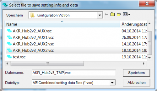
Use a meaningful filename. In this case the system name “AKR”, The hub type “Hub2” and the input for the AC Sensor “TMP” are used. After clicking “Save” the the settings will be saved in a small file.
You can get a summary of your settings:
As a last step you can check the firmware of the ECOmulti:
Configure CCGX
The CCGX (Firmware 1.14) must now be configured. Note that later and more up to date firmware versions behave in much the same manner. Adopt the same principals as below:
- Remove the MK2USB programming cable (grey) from the VE.Bus input, if not done already
- Connect the CCGX VE.Bus cable (blue) to the mainboard.
- Switch on 230VAC mains and loads
- Connect a permanent UTP cable from the CCGX to your Internet router. The router must be configured for DHCP. The CCGX will receive an IP address from the router.
- Configure the CCGX:
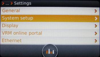
Click on cursor left button and select “Settings”

In “settings” scroll down to “Ethernet” and click right cursor button:

You should see an IP- and a MAC-address. The status should be online. If not, please check your router. whether it is switched to DHCP:

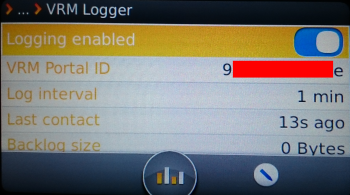
Leave the menu with the cursor left and select VRM online portal:

Note the shown VRM Portal ID (you need it later for configuring your VRM site) and change the logging interval (default = 15min.) to the desired value:
Leave the menu with cursor left and select “Display”:

With the left/right cursor buttons you can change the brightness of the display. The language should be kept as English, the German translation is nearly the same wording. Choose the display off time. Normally 10 minutes is OK:

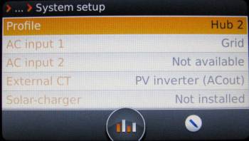
Leave the menu with cursor left and select “System setup”:
Select the profile “Hub2” when your PV system is connected to the output of the ECOmulti:
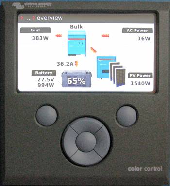
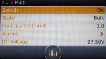
Leave the menu and select “Multi”:
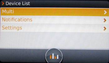
It shows the actual measurement values:
The configuration of the CCGX is finished now.
Check ECOmulti configuration
For the functional check of the ECOmulti you need sunshine to generate PV energy!
- Switch on ECOmulti, wait a minute for booting.
- Switch off AC input (Grid). The ECOmulti should go into inverter mode (look at the CCGX display). After a minute switch on the mains again. You should have charged batteries for this test.
- Switch off loads on ECOmulti output (using the fuse). The batteries should be charged in bulk mode now. If there is enough sunshine, you can leave the loads switched on.
- Switch off the input fuse of the ECOmulti. Use a multimeter to check on the input, whether the ECOmulti feeds back energy to the grid. If the grid is off, the ECOmulti must not do that.
- The last check is to test, whether the photovoltaic feed (230VAC will be switched off, when the ECOmulti has fully charged batteries. Switch off grid and loads and watch the CCGX display. When the PV energy is larger than the energy needed for charging the batteries, the PV inverter should shut down.
Connecting to VRM portal
To see the values of the CCGX in the VRM portal, please follow the instructions in the VRM guide!
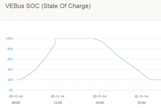
Conclusion
The ECOmulti was saving energy for nightly use in a very effective way. In November, when we have less sunshine, the batteries were fully charged in 3.5 hours. The stored energy is used in the night and lasts for about 5.5 hours. In this case, a second battery set will be useful.
DISQUS
~~DISQUS~~