 Add this page to your book
  Remove this page from your book
  Manage book (
 Help
Help This is an old revision of the document!
Table of Contents
Victron & Freedom Won LiFePO4 batteries - Freedom Lite
Installers Note
Important: It is very important to read this documentation in full and carefully. Freedom Won battery warranties require that you have configured the battery correctly.
Please take special and careful note of the section below on “DC bus pre-charging”.
Introduction
Freedom Won (www.freedomwon.co.za) produces two ranges of LiFePO4 batteries for 48V systems:
- Freedom Lite Home and Business: Eight models available ranging from the smallest 5kWh model (Freedom Lite Home 5/4) up to the 80kWh model (Freedom Lite Business 80/56)
- Freedom Lite Commercial: Ten models available ranging from the 100kWh model (Freedom Lite Commercial 100/70) up to the 700kWh model (Freedom Lite Commercial 700/490).
Note: Refer to Freedom Won website for detailed specification sheets covering all models
These Freedom Lite batteries are fully compatible with the Victron MultiPlus, MultiPlus II, MultiPlus II GX, and Quattro inverter/chargers, Solar charge controllers (VE.Direct and VE.CAN), and system controllers (Color Control GX, Venus GX, Octo GX, Cerbo GX, CANvu GX, Maxi GX).
The Freedom Lite batteries contain an advanced battery management system (BMS) that communicates via a CAN Bus protocol with the Victron GX device. The GX device in turn connects and manages the other compatible devices in the system.
All Freedom Lite models can be connected in parallel with other models of the same capacity, where one Lite (Master) communicates with the GX device as well as all the other Lite’s in the system (Slaves). The Victron and Freedom Won integration has been extensively developed and tested and is certified and supported by both companies.
The system is suitable for all applications, namely:
- Grid Connected with solar and storage including continued operation in grid outage (ESS or self-consumption mode)
- Backup storage or UPS mode
- Off Grid plant with storage and solar
Figure 1 Typical Installation: Freedom Lite 60/42 with Victron 15kVA Quattro and 3x Ve Direct MPPT’s
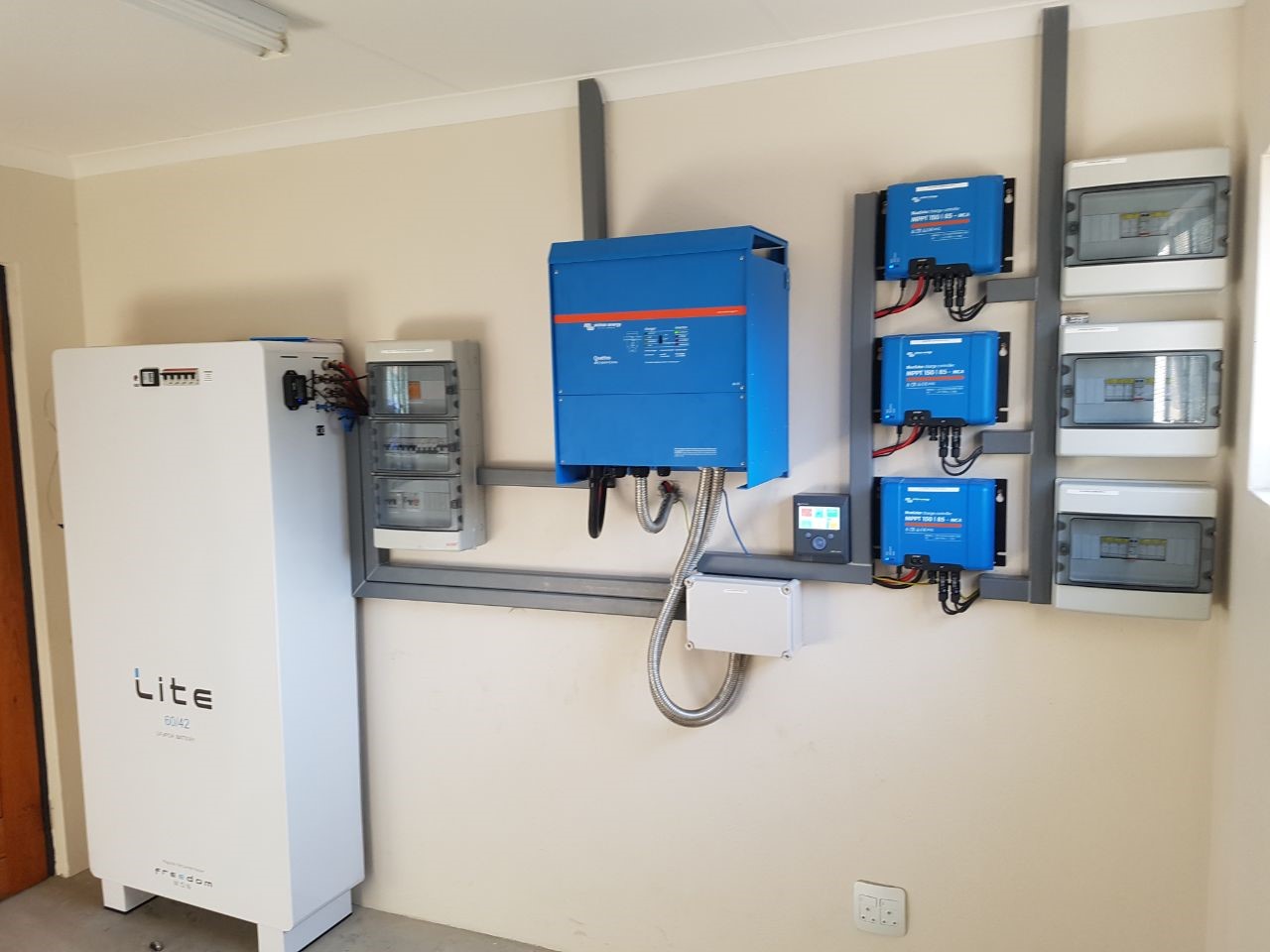
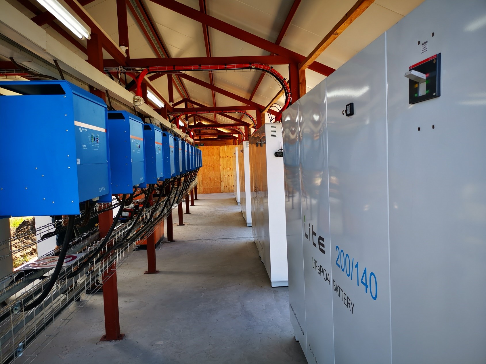
Figure 2 Typical Installation: 7 x Freedom Lite Commercial 200/140 with Victron 12 x 15kVA Quattro and 10 x Ve Direct MPPT’s and 6 x Fronius ECO 27kW
This Manual
This manual is intended to offer Victron specific guidance when designing, installing, and commissioning a Victron – Freedom Lite system. For further details pertaining to the setup of the Victron equipment not pertaining directly to the Freedom Lite interface please refer to the various manuals available on the Victron Energy website eg. Color Control GX manual. Likewise, for further information pertaining to the Freedom Lite batteries, please refer to the Freedom Lite installation manual available from Freedom Won (support@freedomwon.co.za).
Product Compatibility
All new Victron equipment as follows is compatible with Freedom Lite:
- MultiPlus
- MultiPlus II
- MultiPlus GX
- Quattro
- Blue Solar and Smart Solar VE.Direct MPPTs
- VE.Can MPPT’s
- GX-Devices (Colour Control, Venus, Octo, Cerbo, CANvu, Maxi)
NOTE: Certain older MultiPlus and Quattro models containing the smaller microprocessor chip (numbered 19 and 20) are not able to accept the version XXXX4XX firmware and hence are not compatible with the CAN Bus communication from the Freedom Lite battery.
NOTE: If a system includes one or more VE.CAN MPPTs please carefully read the section below on VE.CAN MPPTs.
GX-Device Required
In all cases a GX-device running Victron's Venus OS is required to receive, process, and transmit the commands and information communicated by the battery to the Victron system.
Firmware
In all cases the latest available firmware should be installed on the Victron devices. The Freedom Lite may also benefit from a firmware update if the Victron firmware is being updated on an existing installation. Contact support@freedomwon.co.za for assistance with updating firmware on your Freedom Lite.
Battery Sizing
The Freedom Lite models are rated for specific maximum power discharge and charge levels. It is important to refer to the applicable Freedom Lite specification sheet for the maximum inverter power that may be connected to each specific Lite model. Do not exceed the maximum kVA values provided in the specification sheet for each respective model. For multiple units in parallel, the kVA rating for every Lite in the system may be summed to provide the total allowable inverter installed power.
Further to above, the Lite should be sized so as to provide adequate energy capacity in kWh to meet the load demands of the system and to receive most of the excess solar generation each day (for self-consumption installations).
NOTE: It is not permissible to install an inverter larger than stated in the Lite specification sheet regardless of whether the “Limit DC Discharge Power” ESS feature in the GX-device is used. For instances where the grid is not available this power limiting feature will not operate and the battery could thus be overloaded, causing it to trip. The Lite will also not be able to limit discharge power in the absence of a grid connection. Lastly, the Lite contains a protection circuit breaker that is only rated to handle the power-up inrush current of the inverter for up to the capacity stated in the specification sheet.
Victron-certified Integration
The Freedom Lite transmits, amongst others, the following messages to the GX-device:
- Adaptive Maximum Charge Voltage Set-point – the value transmitted varies from 54.8V to 55.8V depending on the state of balancing on the particular Lite. Typically a well-balanced Lite battery will request a maximum charge voltage of between 55.0V and 55.8V. This advanced feature is only available from Freedom Won and allows superior system control and optimal battery management. The GX-device uses this set-point to control the real time operating or target voltage of the inverter/charger devices and the MPPTs.
- Charge Current Limit (CCL) – this is the maximum current that the battery will accept at any given time stated in Amps. This is a secondary control feature behind the more effective maximum charge voltage control method. This value reduces as the battery approaches 100% State of Charge (SoC). The GX-device uses this value to ensure that the combined Victron system of inverter/chargers and MPPT’s does not exceed the CCL of the Lite. If the CCL drops to zero, the Victron system within a few seconds will ensure that there is no net current flow into the Lite.
- Discharge Current Limit (DCL) – this is the maximum discharge current that the battery is prepared to accept at any given time. This value typically decreases as the battery drops below 10% SoC. The Victron inverter cannot enforce a variable DCL unless in ESS mode were an AC input source can be used to supplement the power to the loads. If there is no AC input source the inverter will stop supplying power to the loads as soon as the DCL drops to zero.
- Additional Battery Information
- Battery temperature
- Minimum battery voltage
- Battery state of charge
- Battery state of health
- Battery voltage
- Battery current
- Battery name
- Highest cell voltage
- Lowest cell voltage
- Highest probe temperature
- Lowest probe temperature
- Battery gross capacity
- Number of batteries online
All of the above information can be viewed in the Freedom Lite device sub menus on the GX-device. Specific setup of the GX-device and the MultiPlus/Quattro is required to ensure the required control is implemented.
If the CAN bus cable is removed or damaged the Victron inverters will shut down within 5 minutes. This prevents continued operation in the absence of communication from the battery. Likewise, the MPPT’s will stop producing power to the DC bus.
DC Bus Pre-charging
Important: Many installers neglect this aspect.
The inrush current when switching on the battery breaker onto the DC bus is huge. This can cause damage to the breaker over time. So it is a Freedom Won requirement that the DC bus is pre-charged before switching on the battery. This is achieved by switch on the AC input to the inverters – the inverters will use the AC power to pre-charge their capacitors. This will eliminate the huge inrush current. The MPPTs can also be used for pre-charging by switching on the solar panels supply to the MPPTs.
CAN Bus Wiring
The connection of the Lite to the GX-device is extremely simple. A standard straight through CAT5e Ethernet cable is required of the desired length, with one end plugged into one of the RJ45 sockets on the Lite and the other end plugged into one of the CAN sockets on the GX-device. Note that the second RJ45 socket in each case must be fitted with an end of line 120Ω resistor. Two are supplied with each GX-device. If multiple batteries are installed in parallel the second RJ45 socket is used to link the next battery in the line onto the CAN Bus network. The termination resistor is installed in the last battery in the CAN Bus line. Refer to Lite installation manual for further information.
Correct CAN Bus communication can be verified by observing whether the Freedom Lite battery is presented in the GX-device list under the name “Freedom Lite”.
Victron VE.CAN MPPTs and Freedom Won Batteries
Note: In this section, the reference to “Color Control GX” refers only to that specific model of GX device and excludes the rest of the range. The limitations described in this section apply only to the Color Control GX (CCGX).
The Freedom Won Battery Management System is configured by default to communicate over CAN bus at a 500kbps baud rate. For systems using a Color Control GX and Victron VE.CAN MPPTs, it is possible to change the baud rate of the battery to 250kbps in order to accommodate the VE.CAN baud rate. However, that is only possible with one battery on a system with a CCGX.
If there are slave batteries on a system, then there are conflicting CAN messages on the bus, and it is necessary to split the battery on the CAN Bus from the devices on Victron's VE.CAN bus. The Color Control GX has a single CAN bus and thus this split cannot be achieved. Therefore, CCGX cannot be used in systems with multiple Freedom Won batteries. In such cases, MPPTs must be swapped out for VE.Direct versions and additional ports can be provided with a USB hub (See “Extending USB ports by use of a self-powered USB hub”). Alternatively, the CCGX can be upgraded to something newer like the Cerbo GX and external display.
Systems with both VE.CAN MPPTs and more than one Freedom Lite battery require a GX device with a dual CAN Bus. The entire GX-device range with the exception of the Color Control GX and the GX built into the MultiPlus II GX have dual CAN buses. In these dual CAN Bus systems, the battery will always run at the standard 500kbps while the VE.CAN bus will run at 250kbps.
Where batteries need to be configured with a profile accommodating 250kbps baud rate for the MPPTs on the can CAN Bus (the standard is 500kbps), the change be made:
- on order by requesting that Freedom Won dispatches the Lite from the factory with baud set to 250kbps; or
- the battery can be reconfigured remotely by Freedom Won with a local PC connected to the battery.
Please contact support@freedomwon.co.za for assistance.
VEConfigure 3 Settings
The MultiPlus or Quattro devices must be correctly configured for operation with the Freedom Lite as follows (note that settings not directly related to the Lite are not mentioned here and must be referenced in the VEConfigure manual).
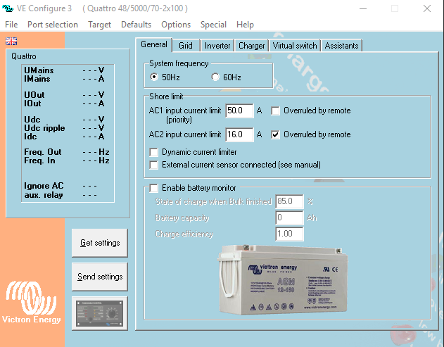
The GX-device must be configured to use the battery monitor provided by the Freedom Won battery and disabling the MultiPlus or Quattro battery monitor ensures that the correct battery monitor is used:
☛ Disable Battery Monitor (the VE.Bus battery monitor is not required with a CAN Bus Lithium battery)
NOTE: It appears that the final step in this process, enabling ESS, turns the battery monitor back on. Please check the General tab on more time once you've complete the process before you save the configuration or upload it.
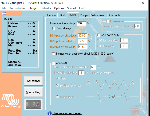
☛ Set the Low Shut-Down, Low Restart, and Low Pre-alarm voltages. The Low Pre-alarm only activates the low battery LED on the inverter and serves no other purpose in this setup. The Low Shut Down and Low Restart voltage settings are usually overridden by the commands from the Lite but offer redundancy in instances of loss of communication and therefore should still be set correctly.
Low Shut-Down: 47.00Low Restart : 52.50Low Pre-alarm: 51.50
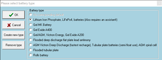
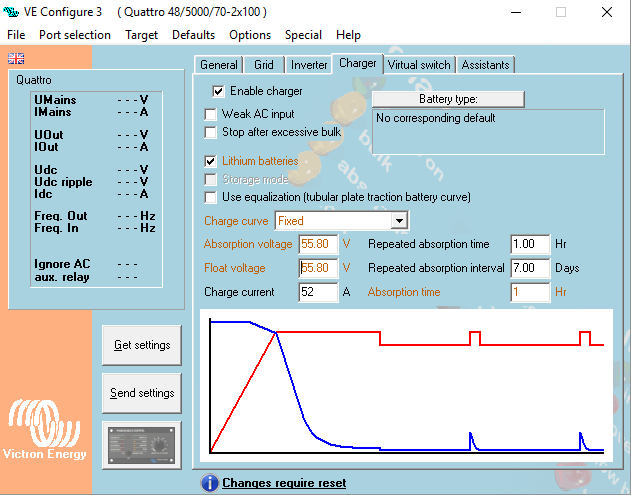
☛ Charger Settings Tab: Set Battery Type as “Lithium Iron Phosphate, LiFePo4 batteries”.
☛ Set Charger Settings. The charge voltage values are overridden by the Lite but should be set correctly regardless for redundancy. The charge current should be set according to the user’s requirements but this value combined with all other charge sources cannot exceed the charge limit of the battery – it is possible to select “Limit Charge Current” on the GX-device as an additional measure to prevent the total system charge current from exceeding the charge capacity of the Lite.
Note: only adjust these values after selecting Lithium battery as the defaults entered by VE.Configure when selecting the Lithium battery type are not suitable to Freedom Won batteries.
✔️ Lithium batteriesAbsorption voltage: 55.80 VFloat voltage : 55.80 VAbsorption time : 1 Hr
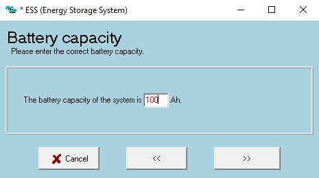
☛ When setting up the ESS Assistant select LiFePO4 battery and enter the Ah value for the Lite (or the combination of Lite’s for a parallel battery system) as per the Ah rating provided in the Lite specification sheet eg. Lite 5/4 = 100Ah.
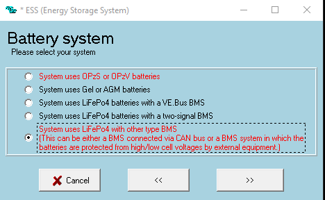
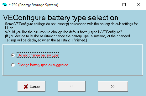
☛ Select – Do not change battery type
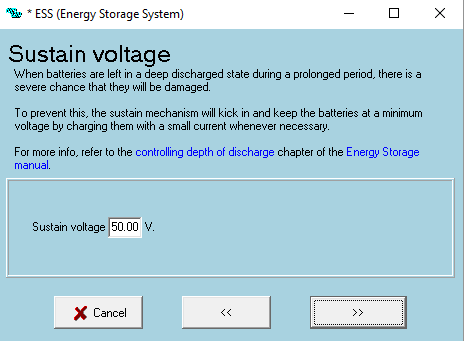
☛Sustain Voltage = 50V
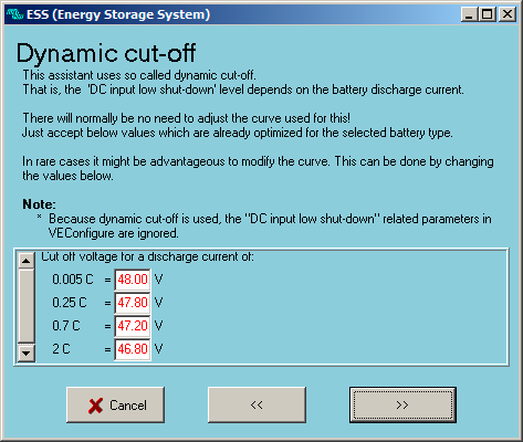
☛ Enter Dynamic Cut-off values as below (usually the Lite will override these values, however they should be entered correctly for redundancy)
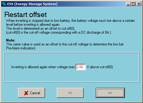
☛ Restart Offset = 2.0V
☛ Go back to General and disable battery monitor again.
GX-Device Venus OS Configuration
It is very important that the following settings are entered correctly for proper functioning of the Lite communication interface:
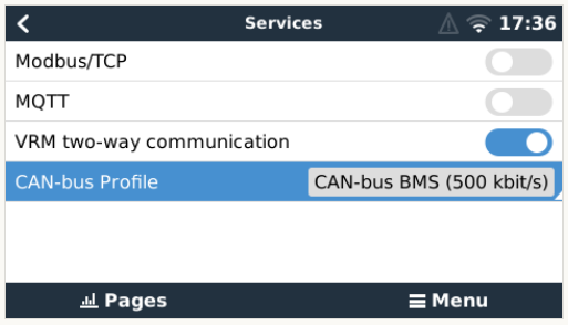
☛ Settings → Services → CAN-bus Profile → CAN-bus BMS (500kbit/s)
Note: For systems with VE Can MPPT’s, select 250kbit/s and ensure Lite profile is also set for 250kbit/s (check with Freedom Won or your Freedom Won distributor).
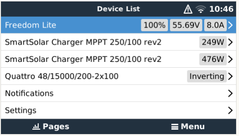
☛ Confirm that the Freedom Lite is showing in the device list as per below
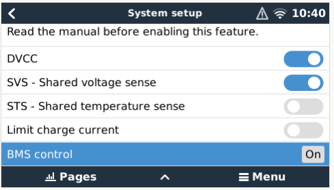
☛ Settings → System Setup → Switch on DVCC and SVS, check that BMS Control is “On”
☛ Freedom Lite (device list) → Parameters → Confirm that the Charge Current Limit and Discharge Current Limit are as per the Lite specifications (Note: if the battery is fully charged the CCL may be reduced. Check that the voltage target is within the range 54.8V to 55.8V (Note: below about 95% SoC the value reflected should be 55.7 or 55.8V. For a fully charged battery this value should range from 55.0V to 55.8V depending on the state of balancing of the cells in the Lite.
MPPT Configuration
The voltage setpoints on the MPPT’s must be set to 55,8V for bulk and float with equalization disabled. In order to do this on the Ve CAN MPPT’s select the User Defined option 8 battery type as this allows adjustment of the charge voltage setpoints.
Adjust the maximum current on the MPPT’s to ensure that the combined total charge power cannot exceed the maximum rated charge current for the Lite or Lite’s in the system.
Troubleshooting
Should any difficulties arise with the Freedom Lite to Victron interface please contact support@freedomwon.co.za for assistance.
DISQUS
~~DISQUS~~