5. Setup
5.1. First setup
5.1.1. First setup via WiFi access point
The charging station broadcasts its own WiFi access point as soon as the charging station is powered for the first time. The following steps describe the first setup to prepare the charging station for operation.
Connect to the WiFi access point:
Scan the QR Code on the internal label.
Or go to the WiFi menu of your mobile device or laptop and manually add the access point that automatically broadcasts its SSID. SSID and WiFi key are noted on a sticker inside the case.
Or scan the QR code shown on the display during the first setup phase. Note that after the first setup, another QR code will appear on the display, linking to the Victron website.
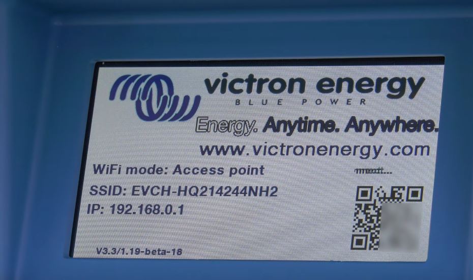
Once connected to the access point, enter the default IP address 192.168.0.1 into a web browser. The First setup process will then start:
WiFi setup: Configure the WiFi network by choosing the WiFi mode
Access point: The unit creates its own WiFi access point. This is either for setting up the unit or in the absence of a separate WiFi network including a GX device. Set SSID, IP address and Netmask according to your needs.
Set SSID, IP address and Netmask according to your needs.
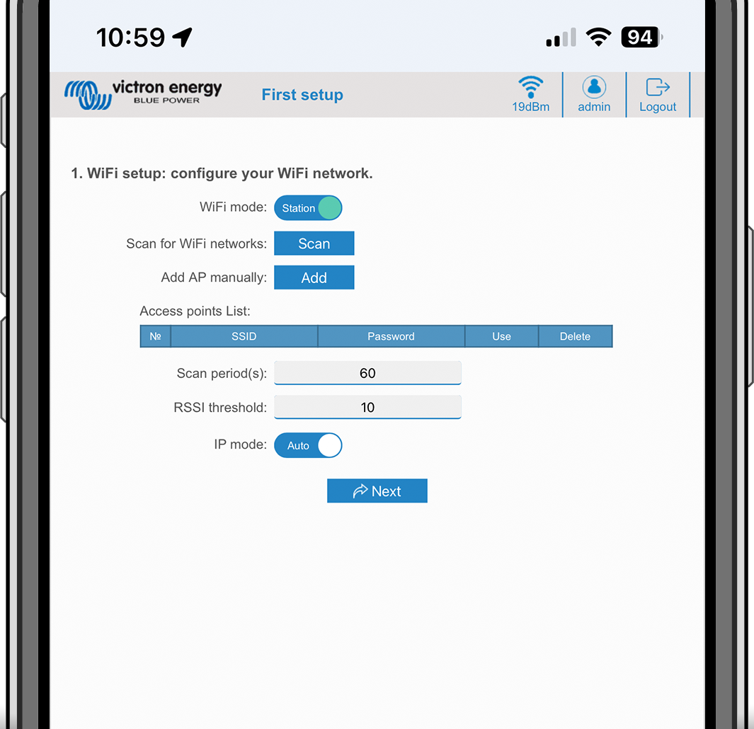
Station: Connects the device to a local WiFi network that includes other Victron devices like a GX device or VRM.
Change the WiFi mode from AP to Station.
Click the Scan button (the scan period and RSSI threshold applies) to search for other WiFi networks or add manually a known AP by clicking the Add button. Note the WiFi standards: 802.11 b/g/n (2.4Ghz only).
Tick the network you wish to connect to and then click Apply.
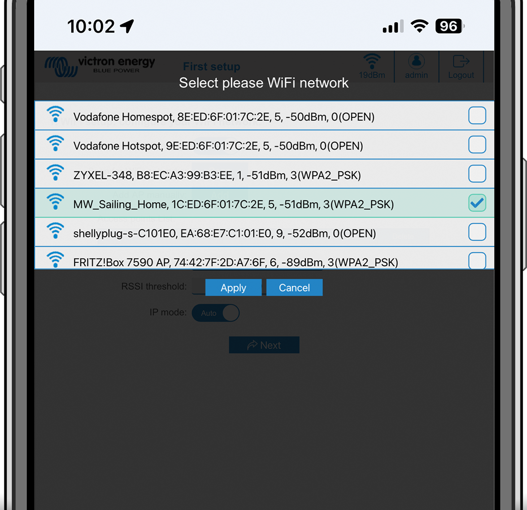
In the Password box, enter the external WiFi password and click Next.
In case you need a static IP rather then DHCP, change the IP mode button to Manual and fill in the static IP address, Mask, Gateway and DNS.

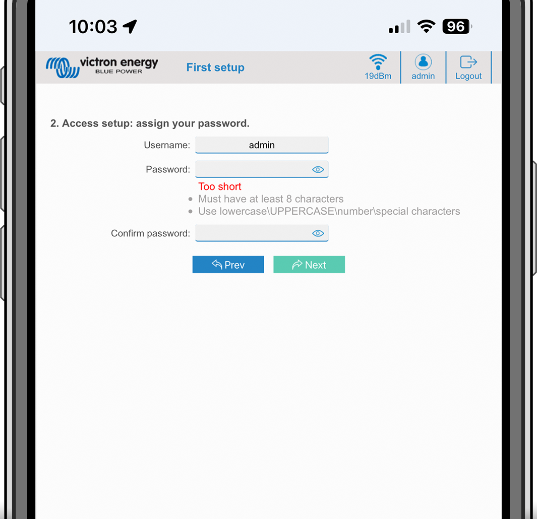
Access setup:
Click into the Username field and type in your own username. The default username is 'admin'.
Click into the Password field and change the password to a new one with at least 8 characters, containing lower, upper and special characters. The default password is printed on the sticker inside the unit.
Confirm your new password.
Click Next.
Charging current setup:
Set the maximum charging current (10 - 32A).

Time zone setup and first setup completion:
Select the time zone region and set the time zone. Daylight saving time is processed automatically.
If UTC is selected as the region, it is necessary to enter the correct offset. Valid time format: +hh:mm or -hh:mm - Example: +02:00 or -01:00

Click Save to apply all settings. The system restarts and the login page of the web interface is displayed.
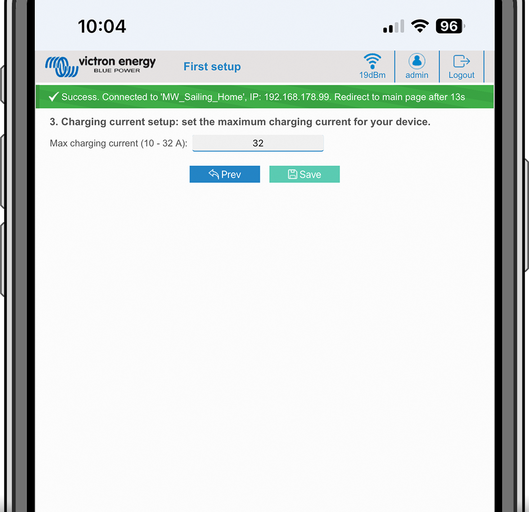
Log in with your credentials that you entered under 3.
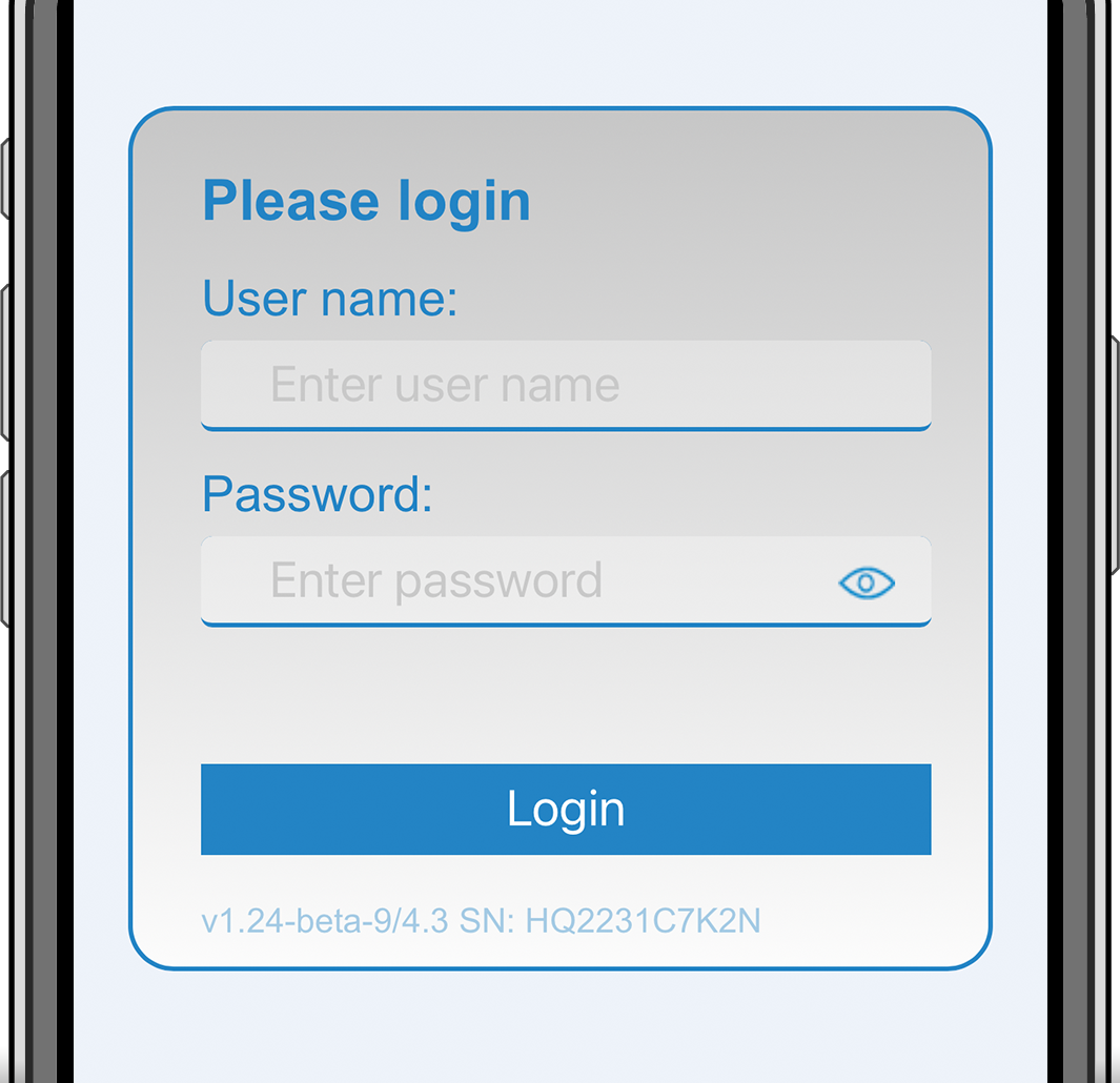
The main page is then displayed and the EV Charging Station is ready for use.

5.1.2. First setup via VictronConnect
Note
Note that operation via VictronConnect requires Bluetooth to be enabled. Bluetooth is disabled on devices shipped with firmware version 1.23 or earlier. In order to enable Bluetooth for these devices, it is mandatory to first go through the First setup via Wifi access point procedure and then activate it via the Networks menu. Devices shipped with firmware version 1.24 and higher have Bluetooth enabled by default.
The first setup is even easier via VictronConnect.
Open VictronConnect and find the entry for your EVCS (EVCS-HQXXXXXXXXX).
Tap on EVCS. This will start the pairing dialogue. Enter the pairing code which is either 000000 or a uniqe number on a sticker inside the housing.
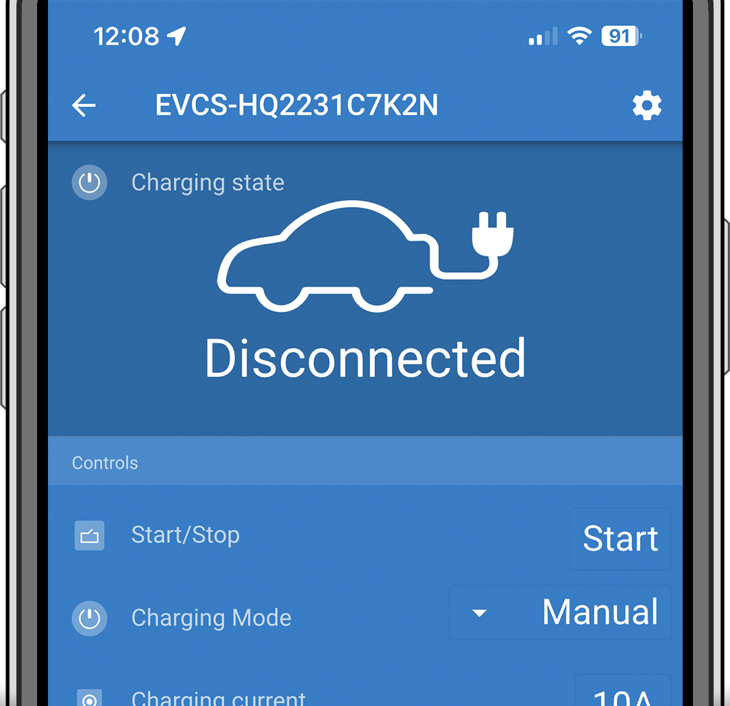
If pairing was successful, the status page will appear; ignore the page for now (using the EVCS is not yet possible) and tap the cog wheel icon in the upper right to open the Settings page.
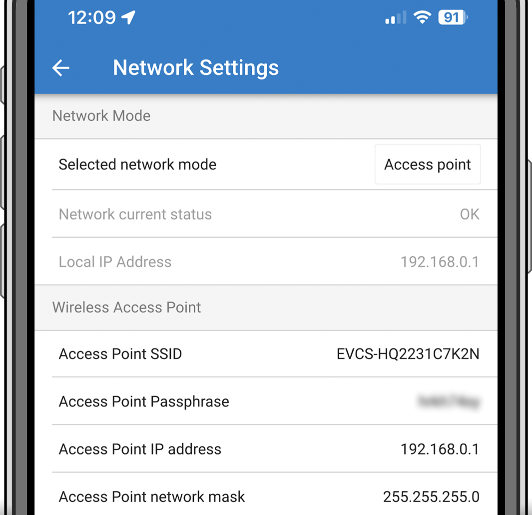
Go to the Network settings and tap on it.

One of the following parameters must be changed to complete the first setup and start using the EV:
Selected network mode: Access Point
The unit creates its own WiFi access point. This is either for setting up the unit or in the absence of a separate WiFi network including a GX device.
If sticking with AP mode, then change at least the Access Point SSID, the Access Point passphrase or the Access Point IP address in the Wireless Access Point settings.
Selected network mode: Connect to local WiFi
Connects the device to a WiFi network that includes other Victron devices like a GX device or VRM.
Change the network mode to Connect to local WiFi, hit OK but do not store the settings yet. Leave the Settings changed popup untouched.

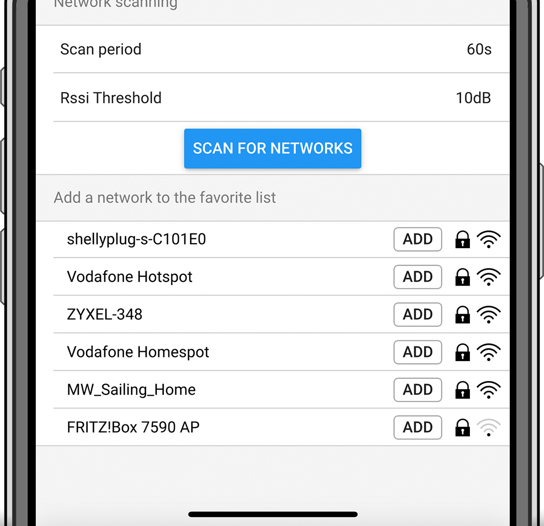
Tap on SCAN FOR NETWORKS and make sure you have the password for your local network ready.

Once the scan is complete, a list of available networks will be displayed. Tap ADD for the network of your choice.
Enter the passphrase for this network in the popup and press OK.
Change the IP configuration if needed: Automatic (DHCP) or Manual for static IP (requires valid IP address, Netmask, Gateway and DNS from your system administrator).

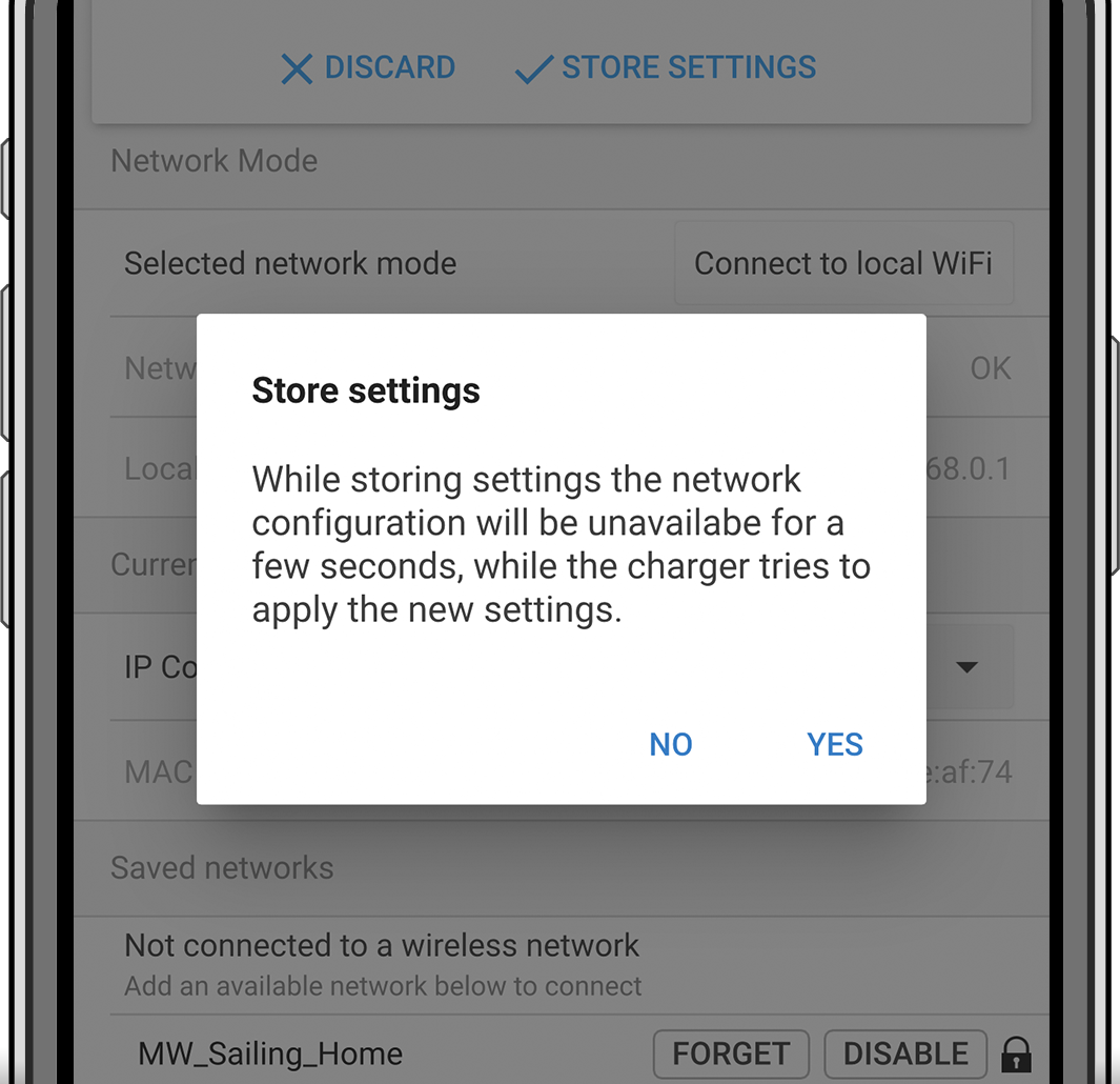
Scroll up and tap on STORE SETTINGS to apply the new settings and confirm with YES. The EVCS will automatically connect to the local network.

The first setup is now finished and the EV Charging Station is ready for use. For more details on how to operate the charging station via VictronConnect, see the VictronConnect setup, configuration and operation chapter
5.2. EV Charging Station setup
After initial setup, set up the EVCS according to your needs. To do this, connect to the web interface and click on the Settings tab for further setting options. The main page options are explained in The main page chapter.
Six subtabs will appear:
Networks tab: See the Networks menu chapter.
General tab: Provides setting options for the charger, GX device communication, display, time zone and device name.
Charger: Charger related settings.
EV charger position: Select where the EVCS is positioned in the system. Examples:
If the charging station is on the output of an inverter as one of the main’s AC outsources, select Inverter AC out.
If connected to the grid and the EVCS is positioned at the AC input of the grid before the inverter, select Inverter AC in.
EV charger autostart: If this option is enabled, the EVCS will attempt to start charging after the vehicle is connected.
Contactor active when charged: Keeps the contactor closed after charging. If. for example, an air conditioner is active in the vehicle, it is powered by AC power and not by the car battery.
Maximum charging current: 10 - 32A
Minimum charging current: From 6A up to 1A below max. value. Example: A Renault Zoe needs at least 10A.
CP line calibration procedure: If the vehicle is not detected or if the vehicle is fully charged and the EVCS contactor opens/closes, the calibration should be performed.
Power calibration(0.6 - 1.4): If the displayed power value is not correct, a maximum correction factor of +/- 40% can be applied.
Actual power (kW): Displays the current power value with which the EV is charged.
GX device: The EV Charging Station can be used:
As a stand alone device in Manual or Scheduled mode. Note that Auto mode requires a GX device and communication between the GX device and EVCS must be enabled.
As part of a larger Victron Energy system. When enabling GX device communication, Modbus TCP must be enabled in the GX device (see Modbus TCP activation section) itself to enable communication with the EVCS.
To avoid errors, the easiest way is to have the pairing between the EVCS and the GX device performed automatically. With the Discover function, the EVCS is able to automatically detect the IP address via the VRM Portal ID.
Communication: Enable or disable communication with a GX device.
IP address: The IP address of your GX device. This will be automatically filled in when you use the Discover feature to pair the EVCS with the GX device.
VRM Portal ID: The VRM Portal ID of your GX device. This will be automatically filled in when you use the Discover feature to pair the EVCS with the GX device.
Discover: Click the Discover button to search for the GX device and pair the EVCS with the GX device. Select the GX device from the list that will pop up; the GX IP address and VRM Portal ID will then be entered automatically.
Check: Press this button to check communication with the GX device. The result is displayed at the top of the page.
Start charging at backup battery SoC(%): The minimum backup battery SoC required to start charging in Auto mode.
Stop charging at backup battery SoC, if off-grid(%): Stops charging when the backup battery SoC falls below this value and there is no grid.
Allow battery/grid power for auto mode: When enabled, auto mode will continue to charge at minimum current when there is insufficient excess solar power. Power is supplied from the grid or battery. This feature is useful to reduce the number of auto-charge enable/disable cycles while charging in auto mode.
Note that EVCS cannot decide where to get power from (grid or battery), it's up to the inverter.
Battery/grid power timeout(min): The maximum timeout to stop drawing current from the battery/grid. This parameter relates to 'Allow battery/grid power for auto mode'.
Overload protection: The EVCS reads the overload statuses from the inverter. When the inverter reports an overload, the EVCS reduces the charging current to the minimum value and waits about 5 seconds. If the overload is still active, the EVCS will stop charging and will not continue until the overload status is no longer present + some timeout.
If the EVCS detects multiple overload situations within a certain period of time, the charging current will be reduced by 10%.
The same applies to off-grid and grid-tied systems. For grid-tied systems, there is also an “input current limit”, and the EVCS will work in the same way as described above if this limit is exceeded.
A warning is displayed on the web interface or in Victron Connect when charging power is reduced or charging is interrupted.
Input current limit(A): In the case of a grid-tied system, it displays the input current limit setting from the inverter, which serves as a threshold for 'Overload protection'.
EVCS ModbusTCP Server:
EVCS ModbusTCP server. The address is the same as that of the GX device.
IP address whitelist state: Enable or disable the whitelist state.
Note that when the IP address whitelist state is enabled, only the devices from the IP address whitelist table below can communicate with the EVCS.
IP address whitelist table: Add IP addresses that are allowed to communicate with the EVCS.
Display:
Active backlight (%): The brightness of the displays when active.
Idle backlight (%): The brightness of the displays when idle.
Active timeout (s): The time after which the active display goes back to idle.
Lock charger display: Enable/disable control on the display.
Hide WiFi credentials: Use this to hide WiFi credentials.
Date & Time:
Region: Select your time zone region.
Time zone/Offset: Select the time zone. If UTC is selected, it is necessary to enter the correct offset.
Valid time format: +hh:mm or -hh:mm - Example: +02:00 or -01:00
Daylight saving time is processed automatically.
Others:
Energy price per kWh: Enter the cost per kWh to calculate the session cost saved.
Device name: Change the name of the EV Charging Station, which will then also be updated in the GX device, VictronConnect and the VRM portal.
Scheduler tab: The schedule required for the scheduled mode is created in this menu.
You can schedule scenes to activate automatically under certain conditions. These conditions include:
Start time: Start time of the schedule in hh:mm (24h time format applies)
End time: End time of the schedule in hh:mm (24h time format applies)
Current[6-32A]: Maximum charging current while the schedule is active
Repeat: The time interval at which the schedule is automatically executed again. Possible options:
Daily: Repeats daily
Mon-Fri: Repeated from Monday to Friday
Weekends: Repeats every weekend
Custom: Choose the days of the week you want the scene to repeat
State: State of the scene. If disabled, the schedule for the scene will not run.
Once a scene has been created, press the Accept button and then the Save button. Note that the scenes are only active when the charging station is in scheduled mode. A currently active scene is highlighted in green in the scheduler and marked active. Scenes can be edited at any time. The same rules apply as described above.
Use the import and export buttons to import/export scenes in .json format.
Light Ring tab: Customises the ring of lights on the front of the station, around the vehicle socket. A variety of modes to choose from, how long the mode is displayed, the brightness of the lights and their colour.
The coloured ring is to indicate at a glance what the EV Charging Station is doing: for example, when the vehicle is fully charged, when there is a low state of charge.
Click the Save button at the bottom of the screen after any change or import/export the Light Ring settings in .json format.
Access tab: Change the username and password.
Backup & FW tab: Export or import saved settings, reset the charging station back to factory defaults and update firmware manually.
FW Update: The EVCS firmware can be updated manually via the web interface or remotely via VRM: Remote firmware update.
Select firmware file (*.evcsup): Press the Open button and browse to the location where the provided firmware file is stored, then click Update. This will start the update process. After a successful update, the charging station restarts and the main page is then displayed again. Note that all settings are retained.
Backup: Backup and restore all system settings from/to a .json format file.
Reset to factory defaults: Resetting the device to default values can be done in different ways:
From the webpage by selecting the Backup & FW menu and then press “Reset to factory defaults” or
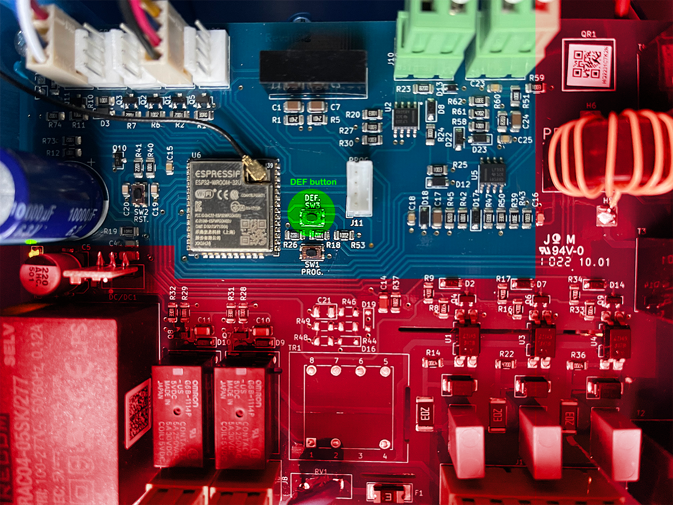
From inside the unit, by pressing the DEF button for more than 15 seconds. See image below. Note that if the DEF button is pressed less than 15 seconds but more than 5 seconds, it will reset the password only.
Warning
The DEF button procedure should only be performed by qualified personnel as this process requires the EV Charging Station to be powered. Working under high voltage is very dangerous and can be fatal if used incorrectly. Be sure to avoid touching parts in the area marked in red.
Via VictronConnect from the product info page.
5.3. The main page
The main page of the web interface provides control and monitoring elements for the EV Charging Station. These are from top to bottom:
Charging mode switch: Change the charging mode to manual, auto or scheduled.
Charging current slider: Adjust the charging current.
Start/Stop button: Start or stop charging when in manual mode.
Note that after pressing the stop button, first the charging current is reduced to a minimum and only then the contactor opens (with a delay of 2 seconds).
Session statistics and an animated graphical overview to see the charging progress at a glance.
|
5.3.1. Charging mode switch in detail
The Charging mode switch is located on the main screen and provides three different operation modes:
Manual mode: Enables the user to turn the vehicle charging ON and OFF manually, using the START STOP button. The amount of current the station provides, can be changed using the Charging current slider.
Automatic mode: The system will determine all the settings for the user. Similar to a GX device, the screen shows how the current is flowing. A GX device such as the Cerbo GX or Color Control GX must be included in the system for this operation mode to work. There are a variety of settings that can be changed directly from the GX device related to either manual or automatic mode. One can see the device, its summary as well as more advanced power graphs on the main dashboard of the VRM Portal.
Scheduled mode: Charge the EV at certain time intervals, for example during the night hours when grid energy is cheaper.
The manual and automatic modes ensure the best use of the charging station.
The charging mode can be changed via:
The charger screen
The web interface
A GX device
The VRM Portal (requires a GX device in the system)
Bluetooth and VictronConnect
The manual mode gives flexibility in choice and charges the car independently of PV production. By manually determining how much power goes into a vehicle charge, you can make allowances for other loads in your home.
The automatic mode ensures maximum efficiency of the PV system and charges excess PV power to the EV before it is fed into the grid.
When the EV Charging Station is connected to a Victron system and is in automatic mode, the excess solar power can be used to charge the vehicle instead of, for example, feeding it into the grid at a lower price.
5.4. Networks menu
WiFi options and Bluetooth are configured via the network menu of the web interface. Available options are:
WiFi
WiFi mode: Toggles between access point and station mode.
Access point mode: The unit creates its own WiFi access point. This is either for setting up the unit or in the absence of a separate WiFi network including a GX device. SSID, password, IP address and Netmask are configurable.
Station mode : Connects the device to a WiFi network that includes other Victron devices like a GX device or VRM. To do this:
Change the WiFi mode from AP to Station.
Click the Scan button to manually search for other WiFi networks or manually add a known AP by clicking the Add button. Note the WiFi standards: 802.11 b/g/n (2.4Ghz only).
Tick the network you wish to connect to and then click Apply.
In the Password box enter the external WiFi password and click Next.
In case you need a static IP rather then DHCP, change the IP mode button to Manual and fill in the static IP address, Mask, Gateway and DNS.
Click Save. Note that when Station mode is enabled, a WiFi strength indicator appears at the top of the web page.
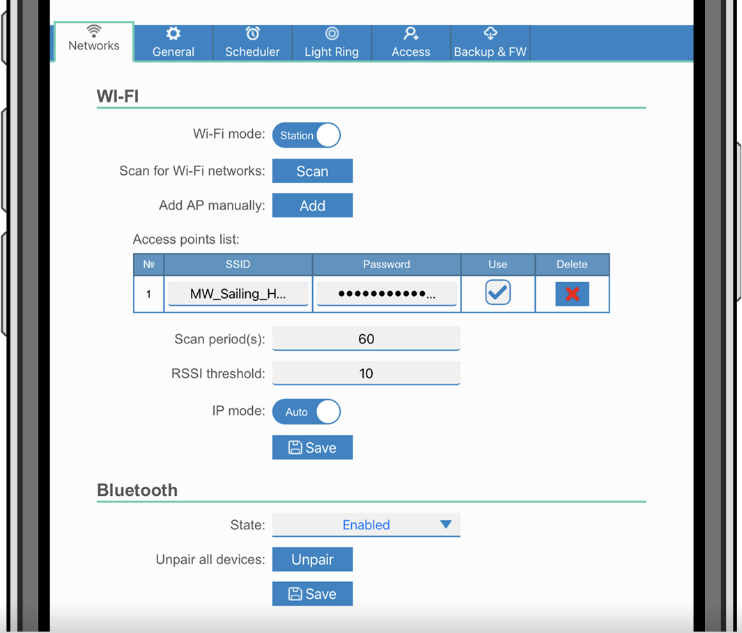
Scan period: If there is only one network to connect to (e.g. a router), the scan period can be set to 0 to avoid unnecessary scanning during an existing connection. If the EVCS connects to more than one network, it is recommended to leave it at the default (60). Note that this is about background network scanning. This parameter has no effect on the manual scan button.
RSSI threshold: An RSSI threshold can be applied to background scanning.
Bluetooth
Bluetooth establishes a direct wireless connection between a mobile device and the EV Charging Station to control and monitor the EVCS via VictronConnect. The distance is usually a few meters indoors.
Note that Bluetooth is disabled on devices with firmware version 1.23 or earlier and must be manually enabled before VictronConnect can be used. The default pairing code for this is 000000. Devices shipped with firmware version 1.24 and higher have Bluetooth enabled by default. The pairing code for this is located inside the housing and is unique.
The pairing code can be changed via VictronConnect. A factory reset resets the pairing code to factory defaults.
To enable, disable or unpair Bluetooth via the network menu, the following options are available:
State: Enables or disables Bluetooth functionality. A change requires pressing the Save button to apply the new status.
Unpair all devices: Click to unpair the EVCS from your mobile device(s). Note that this will also restart the charging station and you will still need to remove the pairing from your mobile device's Bluetooth menu.
5.5. Access menu
In the Access menu you can choose your own username and password (strongly recommended). Note that you will be prompted to change the password during the initial setup.
To change the username and password:
Click into the Username field and type in your own username.
The default username is 'admin' (without apostrophe).
Click into the Password field and change the password to a new one with at least 8 characters, containing lower, upper and special characters.
The default password is printed on the sticker inside the unit.
Confirm your new password.
Click Next.
In case the password is lost, see the Reset to factory defaults and password recovery chapter.