 Add this page to your book
  Remove this page from your book
  Manage book (
 Help
Help This is an old revision of the document!
Table of Contents
Venus GX manual
In many ways the Venus GX and the Color Control GX are the same device. They share a lot of hardware, and they run on identical software - our 'Venus OS' - therefore firmware numbering is the same; and new version releases always apply to both devices at the same time.
Venus GX/CCGX comparison table
Use the Venus GX / CCGX comparison table in Paragraph 4. below below to see the similarities and differences between the two devices at-a-glance.
(This manual refers to the latest firmware version. A device connected to the internet will perform new-version updates automatically. Check the latest firmware version here.)
1. What's in the Box?
- Venus GX
- VE.Can terminator (2 pcs).
- Power cable with inline fuse and M8 terminal eyes for battery- or DC busbar-attachment.
- Terminal Blocks for all the connectors on each side.
- Label showing wifi key and product details.


1.1 Overview of connections

2. Accessing the device
Because the Venus GX has no visual display or buttons, it is accessed for setting-up and monitoring by using the 'Remote Console' feature. You can do this through VRM, using the built-in WiFi Access Point, or by using the local LAN/WiFi network.
2.1 Accessing 'Remote Console' via VRM
Connect the Venus GX to the internet by plugging it into a working Ethernet network which as a DHCP server (most networks do). It will immediately connect to VRM.
Go to https://vrm.victronenergy.com/ and follow the instructions to add the device. More information about this is available in the VRM Manual.
When you've done that, click the 'Remote Console' link to open the window, like this:
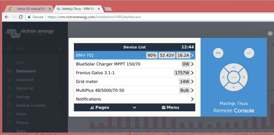
More information about 'Remote Console' on VRM is explained here.
2.2 Accessing 'Remote Console' via the built-in WiFi Access Point
Steps:
- Make sure you are no further than a few metres away from the Venus GX
- Go to the WiFi settings on your phone / tablet / laptop.
- After searching, it will show up in the list:
- Connect to WiFi using the 'WiFi key' which you will find printed on the side of the box …and also on a card in the plastic bag - which you should keep in a safe place.
- Once connected, navigate to 172.24.24.1
Note that for added security it is possible to disable the WiFi Access Point. See Settings → Wi-Fi → Create access point.
Caution: Once WiFi Access is disabled the only way to get it back is by using 'Remote Console' on VRM -which requires a working internet connection; or via 'Remote Console' on LAN which requires a working network connection (but no internet).
2.3 Finding the IP address
If you've accidentally disabled Remote Console on VRM, the only way to re-enable it is via Remote Console on LAN. And to do that you'll need to find the IP address of the Venus GX. There are several ways of finding it:
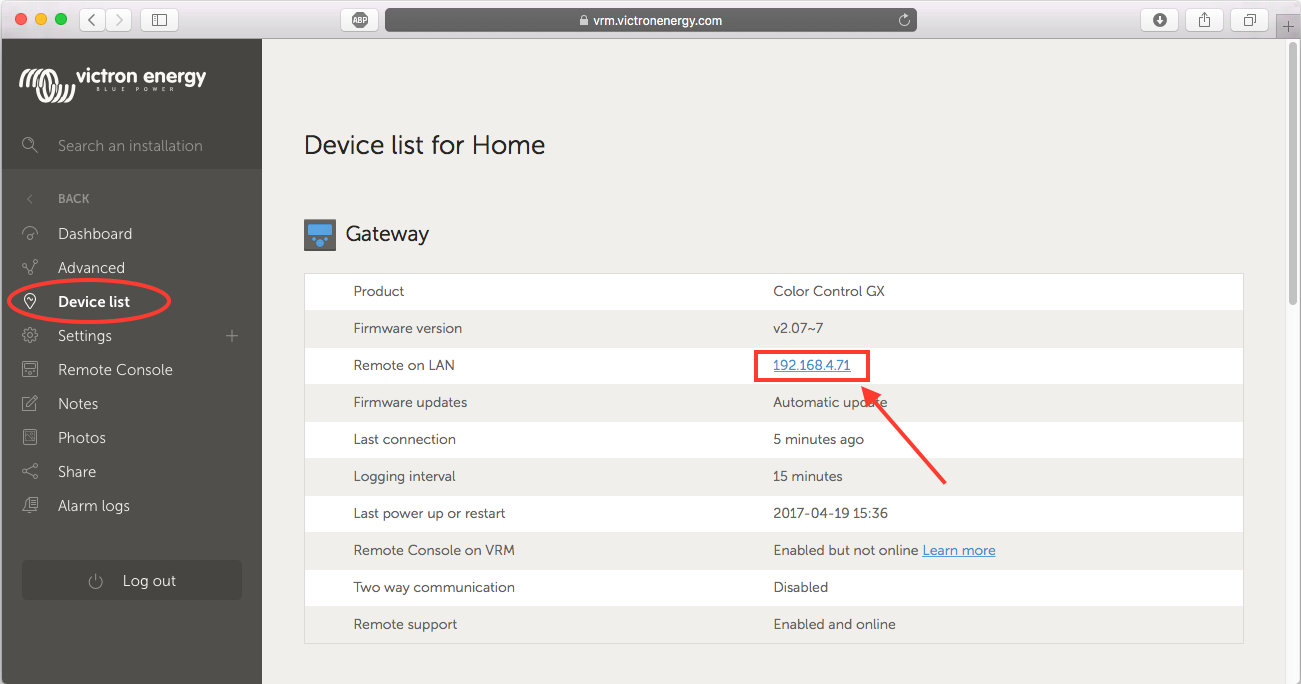
IP Address on VRM
On VRM, you'll find the IP address on the Device List page of the installation. Note that this does require the Venus GX to be connected to the internet.
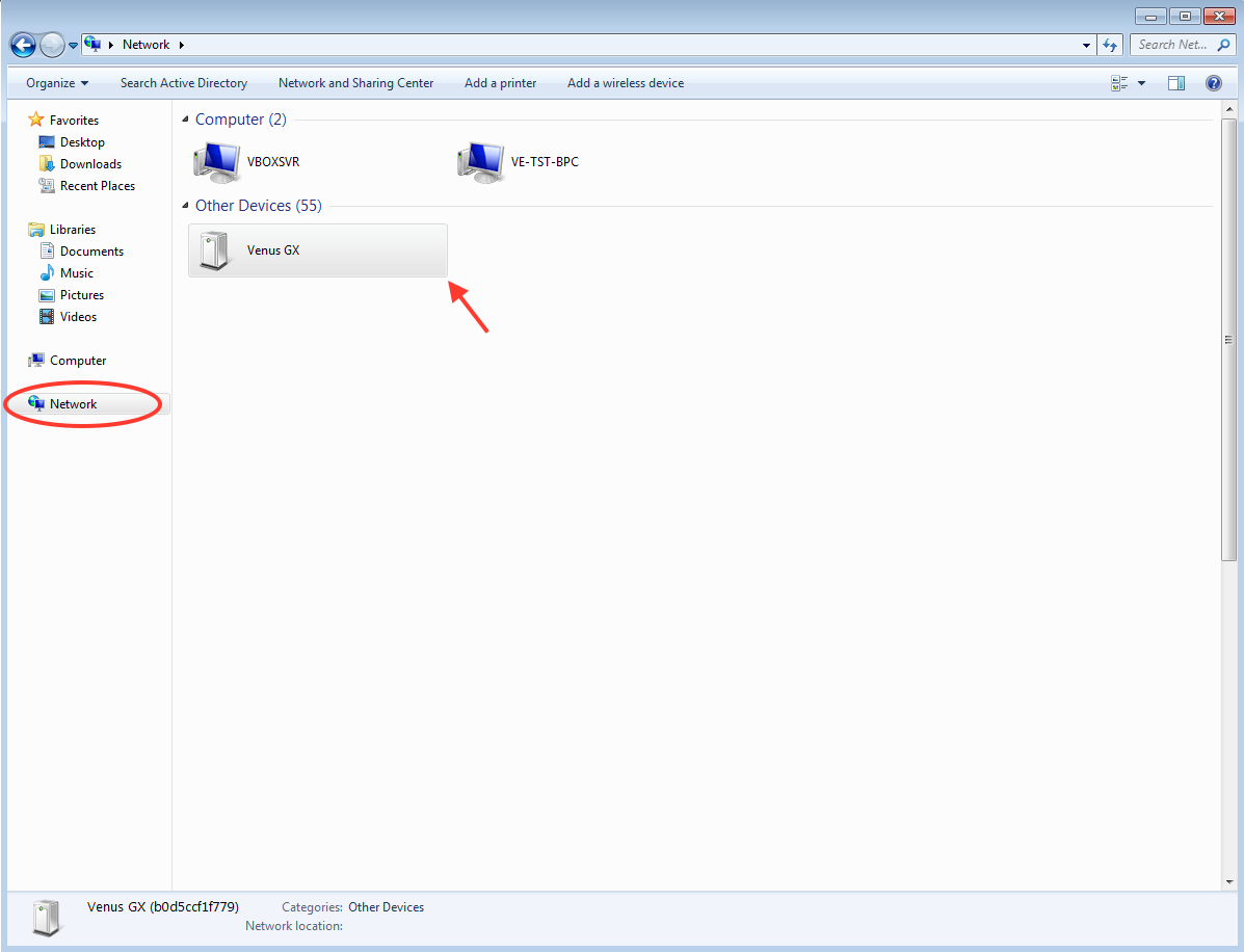
Network (on Microsoft Windows)
In a local network, for example at home, you can also find the Venus GX in the Windows 'Network' overview:
Double-clicking the icon will open up Remote Console on LAN.
Open the 'Properties' window to see the IP address.
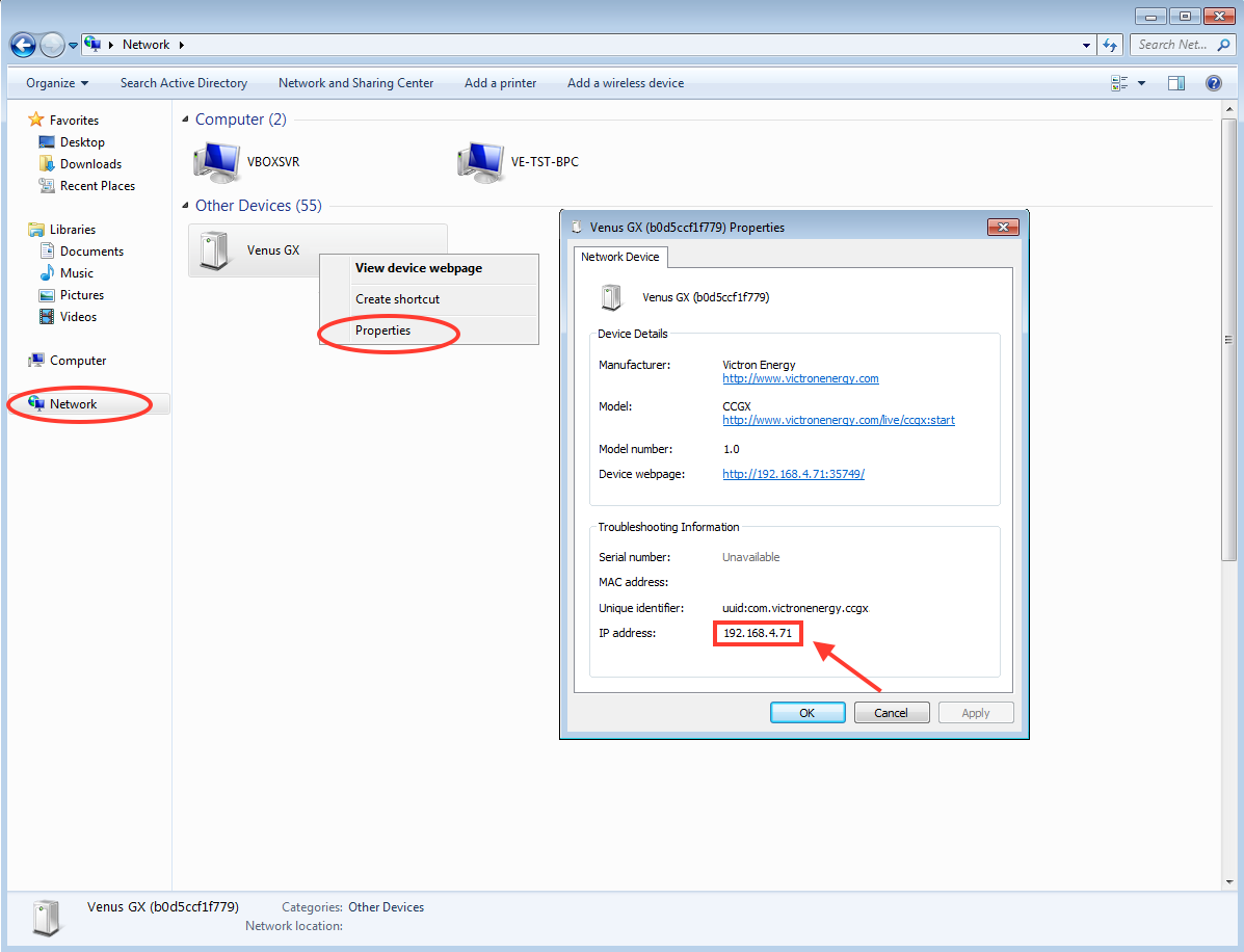
This uses Universal plug-and-play broadcast technology.
3. LEDs and Push-button - explanation
3.1 LEDs
Boot-up
On the side of the Venus GX, there is an LED. During power-up it it goes through these states:
- Stage 1: Both green and red illuminate briefly and faintly (it's hard to see the green) for approximately 1 second.
- Stage 2: Red illuminates for approximately 1 second.
- Stage 3: Green illuminates for approximately 0.5 seconds.
- Stage 4: Both green and red illuminate briefly and faintly (it's hard to see the green) for approximately 1 second.
After that the LED will be blinking green continually.
Factory re-install
During a forced factory re-install - a very uncommon operation - the LED has these definitions:
- Off: No action is being taken.
- Red blinking: Re-install in progress.
- Green illuminated: Re-install complete.
- Red illuminated: Error.
3.2 Small button located to the right of the green 14-Terminal Connector Block
This button has no function allocated at present.
4. Digital Inputs
The Venus GX has five digital inputs. The channels are accessible via the RJ-12 socket on the side. This is available for self-wiring by the user/installer.
Limitations Note that in the event of an alarm, it does not show on the Notifications page yet. Also the status, and also pulse counter data, is not visible on the VRM Portal yet.
4.1. Wiring details
The inputs are non-isolated. They operate at 3V3 levels, and can withstand up to 5V input. Each input has an internal 10k pull-up resistor to 3V3. We recommend wiring it to a potential free relay or otherwise open collector/optocoupler output.
| RJ12 pinout | Input |
|---|---|
| pin1 | input1 |
| pin2 | input2 |
| pin3 | input3 |
| pin4 | input4 |
| pin5 | gnd |
| pin6 | input5 |
4.2. Configuration
Each of the digital inputs can be configured as a pulse meter, or as one of a number of predefined sensors that can also be configured as alarms.
The possible configurable functions are:
| Function | States |
|---|---|
| Pulse meter | N/A |
| Door alarm | Open/Closed |
| Bilge pump | On/Off |
| Bilge alarm | Ok/Alarm |
| Burglar alarm | Ok/Alarm |
| Smoke alarm | Ok/Alarm |
| Fire alarm | Ok/Alarm |
| CO2 alarm | Ok/Alarm |
| Generator | Running/Stopped |
The function of each input can be configured in the GUI under Settings → I/O → Digital Inputs.
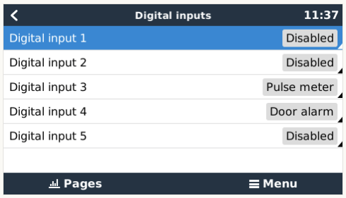
Once the input is configured for its intended purpose, it will show up with other devices.
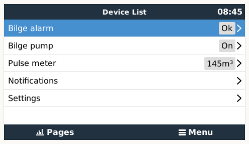
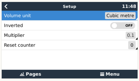
Other parameters related to that function can be configured by entering the device menu and selecting Setup. For pulse meters, you can configure the unit, the multiplier (the volume represented by each pulse) and reset the counter.
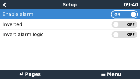
For other sensors and alarms, you can decide whether the input should be treated as an alarm condition, whether the labels should be inverted, and whether the logical levels should be inverted.
- To swap the labels attached to the alarm, set Inverted to on.
- If a logical low input (0V) should be considered a positive condition, set Inverted alarm logic to on.
4.3. ModbusTCP
The values/states of the digital inputs are available on ModbusTCP. For more details about this, please download a copy of the document “Modbus-TCP register list” from our website.
5. How does the VenusGX compare with the CCGX?
This section explains all the differences between the two devices.
If you are familiar with the CCGX you will see at a glance how it compares to the Venus GX.
| User interface | CCGX | Venus GX |
|---|---|---|
| LCD Display & 7 buttons | yes | no |
| Remote Console | yes | yes |
| Victron comm. ports | CCGX | Venus GX |
| VE.Direct | 2 dedicated ports - isolated (1) | |
| VE.Can | 2 paralleled RJ45 sockets – isolated | |
| VE.Bus | 2 paralleled RJ45 sockets – isolated | |
| Non Victron-products | CCGX | Venus GX |
| Canbus-BMS batteries | Many battery brands. See here for details | |
| Fronius PV Inverters | See here for details | |
| Communication | CCGX | Venus GX |
| USB | 2 USB Host ports – not isolated | |
| Ethernet | 10/100 RJ45 socket - isolated except shield | |
| WiFi | optional (2) | built-in, but see (3) |
| Bluetooth Smart | no | future function (4) |
| Micro SDcard slot | SDHC cards up to max. of 32GB. (5) | |
| Second CAN-bus port | no | future function (6) |
| IO | CCGX | Venus GX |
| Programmable relay (7) | 1x NO | 1x NO / NC (8) |
| Resistive tank level inputs | no | 3 (9) |
| Temperature measurements | no | 2 (10) |
| Digital Inputs | no | 5 |
| Other | CCGX | Venus GX |
| Outer dimensions ( h x w x d ) | 130 x 120 x 28 mm | 45 x 143 x 96 mm |
| Operating temperature | -20 to +50°C | |
| Standards | CCGX | Venus GX |
| Safety | EN 60950 | |
| EMC | EN 61000-6-3, EN 55014-1, EN 61000-6-2, EN 61000-6-1, EN 55014-2 | |
| Automotive | E4-10R-053535 | In progress |
Notes:
- The maximum number of VE.Direct devices on a CCGX is 5 (2 normal and 3 via USB). The maximum number of VE.Direct devices on a Venus GX is 6 (2 normal, and 4 via USB).
- Though the CCGX has no built-in WiFi it can easily be added by attaching a USB-WiFi dongle. See CCGX Manual, section 1.4.2 for details.
- The built-in WiFi in the Venus GX has a very low signal strength - unfortunately. The strength is sufficient for connecting to a phone, tablet or laptop in order to access setup and monitoring. But to connect the Venus GX to the internet either use the built-in Ethernet port or add a USB-WiFi dongle. See CCGX Manual, section 1.4.2 for details. Make sure the Venus GX is running v2.06 or later - the first shipment of Venus GX units ran v2.05.
- The hardware of the Venus GX contains a Bluetooth Smart chipset - but there is no function for it in software yet.
- Larger SD memory cards (SDXC) are not supported. SD cards can be used for two purposes:
- Logging data, see this section in the ccgx manual for details.
- Updating firmware, see this section in the ccgx manual for detials.
- The second CANbus port is accessible via the GND, CAN-H and CAN-L terminals on the left of the product. This port is available for future developments and has no functionality at present.
- The programmable relay can be set to act as an alarm relay, automatic genset start stop, or an on/off switch, and is controlled via the GUI and/or ModbusTCP.
- In the Venus GX hardware there are two relays - at present only one of them is available for use.
- The tank level inputs are resistive and should be connected to a resistive tank sender. Victron does not supply tank senders. The tank level ports can each be configured to work with either European (0 - 180 Ohm); or US tank senders (240 - 30 Ohm).
- The Venus GX has two temperature terminals which can be used to measure & monitor all kinds of temperature-inputs. Temperature senders are not included. The required sensor is ASS000001000 - Temperature Sensor QUA/PMP/Venus GX. (Note that this is not the same as the BMV temperature accessory.)
6. More information
DISQUS Comments
~~DISQUS~~