 Add this page to your book
  Remove this page from your book
  Manage book (
 Help
Help This is an old revision of the document!
Table of Contents
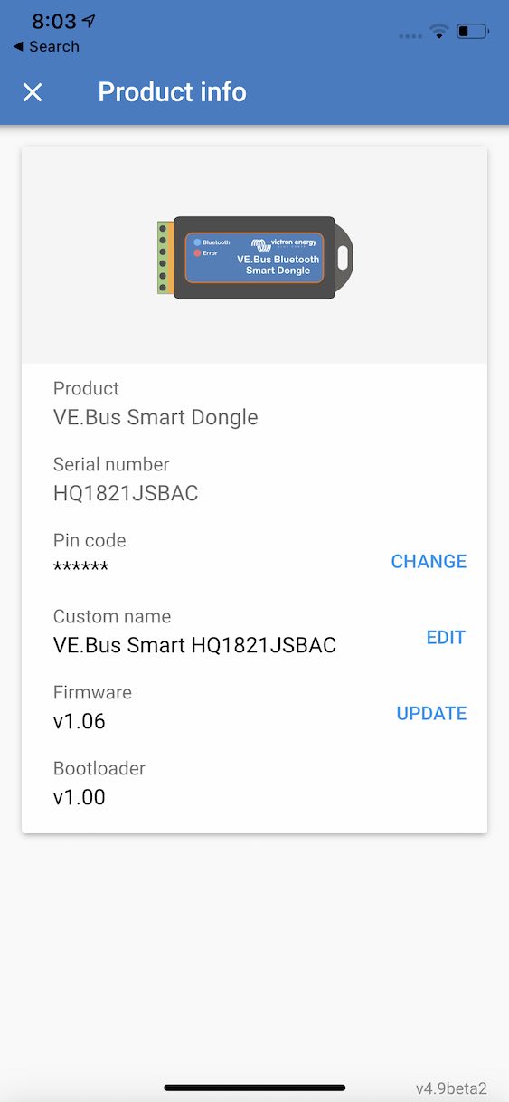
VE.Bus Smart Dongle - manual

System requirements
Multi firmware versions before 415 are not supported
| Function | Minimum Multi firmware version | Note |
|---|---|---|
| Battery voltage and temperature sense | 419 | |
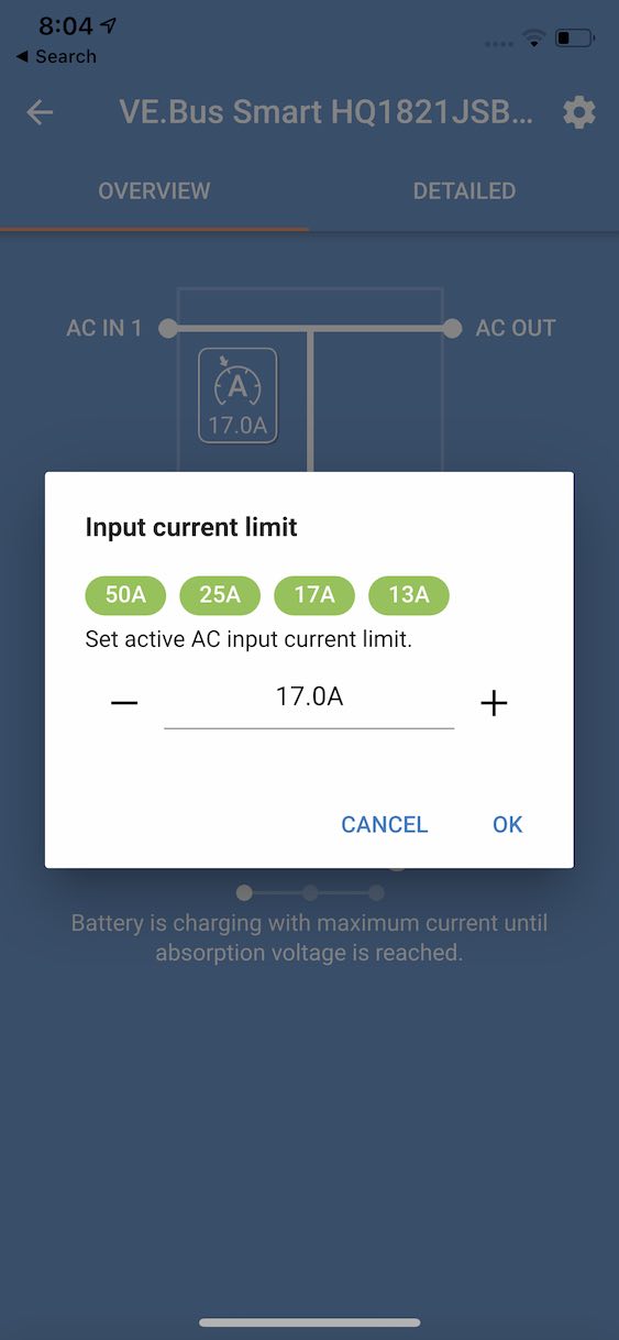
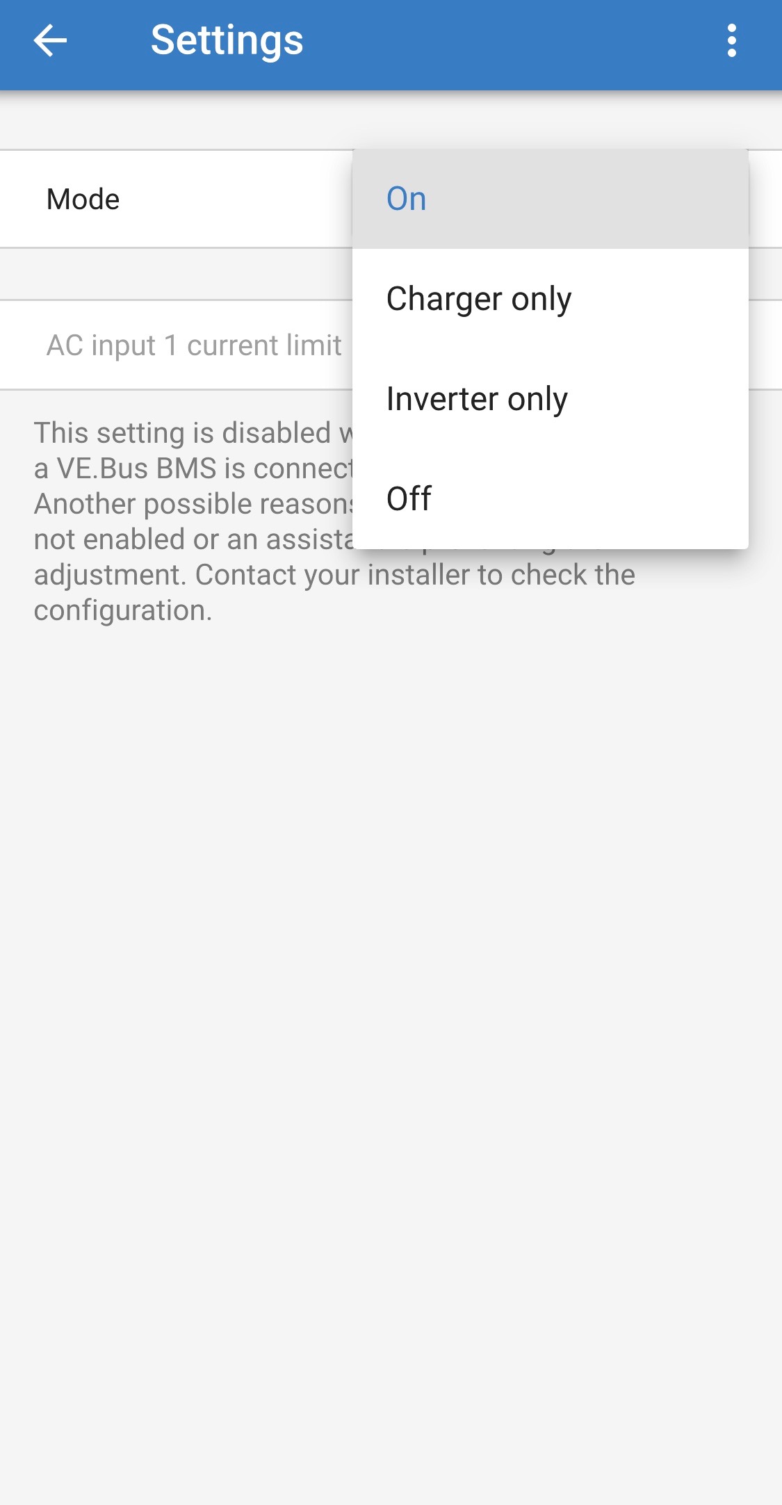
| Input current limit and on/off/charger only control | 415 | Not supported when a DMC and/or VeBus BMS is installed |
Introduction
The VE.Bus Smart dongle is a Bluetooth Smart enabled VE.Bus interface, with battery temperature-and-voltage sensing. It communicates system information straight to your smart phone - using the free-to-use VictronConnect app.
The VE.Bus Smart Dongle does not provide full programming functionality - please also read this VictronConnect VE.Bus manual for more specific information on programming limitations.

When used with Multi- inverter/chargers the dongle provides on-battery temperature and voltage sensing capabilities - allowing compensation for possible cable losses which can occur during charging and discharging. Temperature sensing allows accurate temperature-compensation during battery charge cycles. The dongle is, at present, the only way to add an “on-battery” sensing capability to the MultiPlus-II models, if they are not also connected to a GX device and CANbus battery.
The dongle can be used in systems with or without a GX device - such as the CCGX. In systems with a GX device, and another source of temperature and voltage data (eg from a CANbus battery), the CCGX data will override temperature and voltage information from the dongle. In this role the dongle will still provide live-information via its VictronConnect interface; and it will provide firmware updates without requiring an internet connection.
When the dongle is used in systems which do not have a GX device, the dongle's voltage and temperature data becomes the primary source of that information, and can be used by other connected devices for voltage compensation.
In systems with a Multiplus-II, dongle and GX device, but no other source of temperature and voltage, the data from the dongle will also be used.
At this time, the VE.Bus Smart dongle cannot send its temperature and voltage data as part of a VE.Smart network.
The VE.Bus Smart dongle is able to sense battery temperature in two ways: The default method is the dongle's on-board temperature sensor. When the dongle is mounted directly onto the battery case (using its adhesive attachment) it will sense the battery temperature directly from the battery casing. The second method - which provides improved battery temperature sensing - is available by using an optional battery-terminal mounted sensor. When this sensor is connected, the default sensor is overridden and the dongle will use this method instead.
The terminal connection on the VE.Bus Smart dongle marked 'Relay' has no function, and is not used.
What's in the box
- VE.Bus Smart Dongle
- Red battery (+) connection wire with 10mm eyelet and inline fuse.
- Black battery (-) connection wire with 10mm eyelet
- Connector block with screw terminals.
* Note the standard UTP RJ45 cable that is required to connect the VE.Bus Smart Dongle to the Multi's VE.Bus interface is not included. You can use an existing network cable, or buy one separately from Victron in the length that you require for that specific installation.
Optional accessories :
- External battery-terminal mounted temperature sensor (ASS000100000). (NOTE: Currently the temperature sensor is shipped with a label “CAUTION: BMV702 only!”. This caution can be ignored for the VE.Bus Smart dongle)

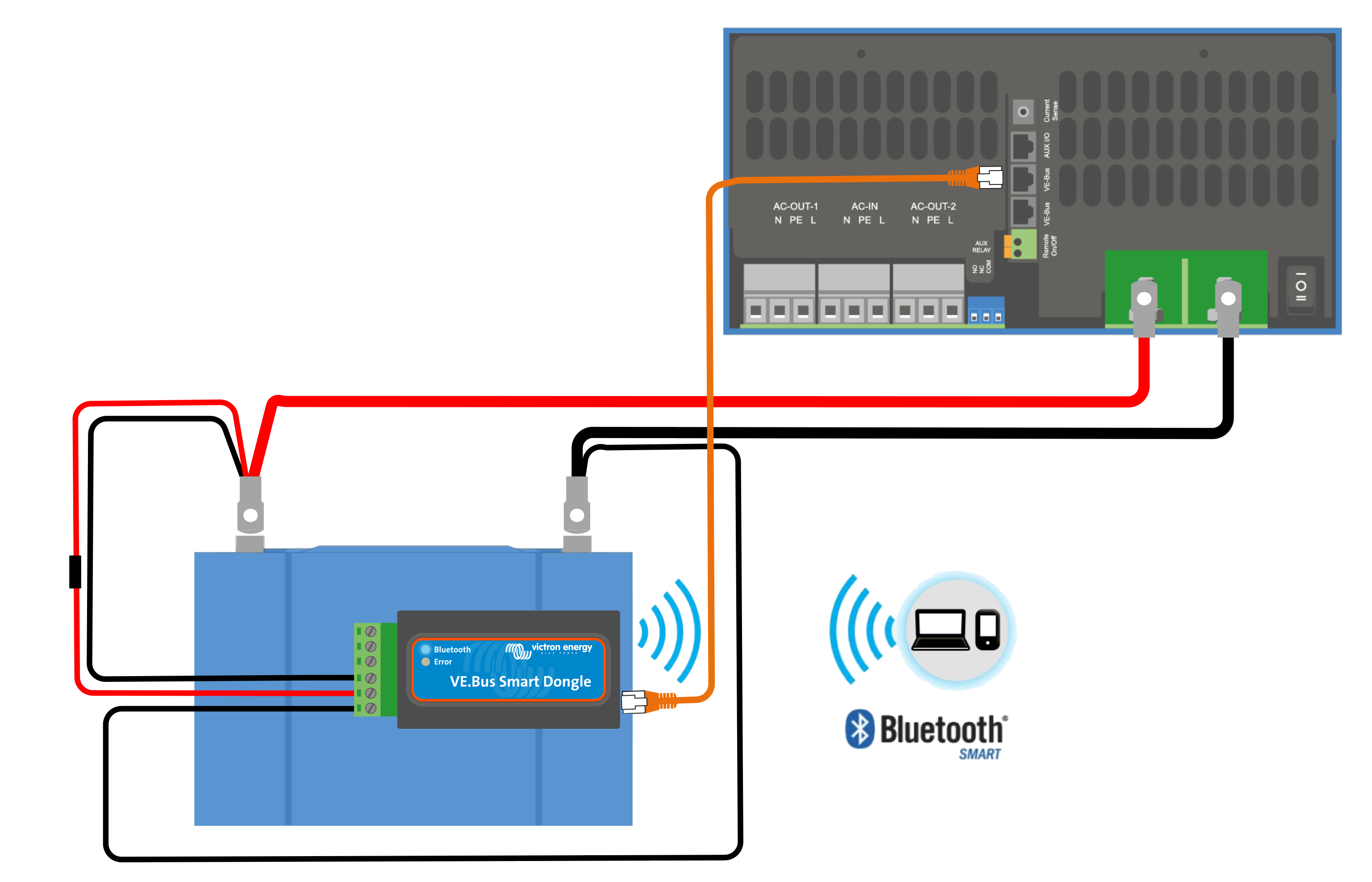
Installation
Installation without battery sensor:
- Connect the red connection wire to the B+ input on the connection block
- Connect the black connection wire to the B- input on the connection block
- Connect the two eyelets to your battery terminals. Red wire eyelet on bat+ , black wire eyelet on bat-
- For battery temperature sensing, mount the dongle on or near the battery using the dongle's adhesive mounting. If mounted near the battery, screws can be used.
- Plug the connector block into the dongle.
- Connect the dongle to the Multi's Ve.Bus interface, using a standard RJ45 UTP cable
Installation with battery terminal temperature sensor:
The battery temperature sensor replaces the included red battery(+) connection wire.
- Connect the temperature sensor's red connection wire to the B+ input on the connection block
- Connect the temperature sensor's black connection wire to the T- input on the connection block
- Connect the black connection wire to the B- input on the connection block
- Connect the two eyelets to your battery terminal. Red wire eyelet on bat+ , black wire eyelet on bat-
- Mount the dongle on or near the battery using the dongle's adhesive mounting. If mounted near the battery, screws can be used.
- Plug the connector block into the dongle.
- Connect the dongle to the Multi's Ve.Bus interface, using a standard RJ45 UTP cable
LED Status codes
Ve.Bus Smart has two LEDs: a Bluetooth status LED (blue), and an Error LED (red).
On power-up, the Bluetooth LED will be slow-blinking - indicating that the device is ready to accept a Bluetooth connection.
If both LEDs remain illuminated, something is wrong with the Ve.Bus Smart unit (Hardware error).
When the LEDs are alternating quickly for more than 30 seconds, the Ve.Bus Smart is in firmware update mode and will need to complete the update before it can be used. Firmware updates are performed (where necessary) after connecting to VictronConnect.

| Blue LED | Red LED | Ve.Bus Smart dongle state | Connection State | Remark |
|---|---|---|---|---|
| On | On | Not functional | Disabled | Hardware error. Ve.Bus Smart will not be visible in VictronConnect and it will not transmit battery temperature and voltage data to the Multi |
| Slow blinking | Off | Operational | Not connected | |
| On | Off | Operational | Connected | |
| Fast blinking | Fast blinking | Firmware update | Not connected | Red and Blue LED Alternating |
| On | Slow blinking | Firmware update | Connected | |
| On | Faster blinking | Firmware update | Uploading | |
| Fast blinking | Off | Firmware update | Programming |
Modes of operation
The dongle can operate both as a primary and a background information source. It will assume either role automatically depending on whether a GX device (CCGX/VenusGX/OctoGX) is present in the system.
Due to restrictions in the VE.Bus communication protocol only one device can access data such as power readings.
A GX device has priority over the dongle and should always be able to access all data. When power is applied to the dongle - or after a firmware update - the dongle will startup in background mode. VE.Bus communication ports will be monitored for 30 seconds. If during this time no GX device is detected the dongle will switch to primary mode, and all supported data will be available. While switching modes VictronConnect will temporarily indicate an “unknown” VE.Bus state. The dongle continuously monitors GX device activity on the VE.Bus. As soon as a GX device is detected it will switch itself to background mode.
Likewise, the dongle also monitors VE.Bus communication in order to discover if a GX device is supplying the Multi with battery voltage and temperature data. It takes around 4 minutes after power on, or reset, before the dongle decides whether or not to transmit the battery voltage and temperature.
When no Multi is connected VictronConnect will list the 'VE.Bus Smart Dongle' in the device list. In this case the dongle can be used as a Voltage/Temperature sensor.
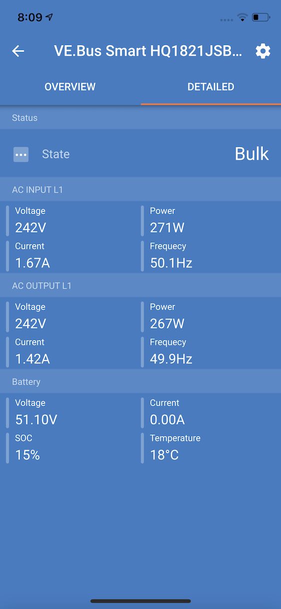
It takes a bit of time before a Multi is detected. When the dongle detects a Multi, VictonConnect will identify the Multi in the Device list. Shortly after updating the firmware in VictronConnect only the dongle will show up in the device list. If connected, a re-scan will reveal the Multi.
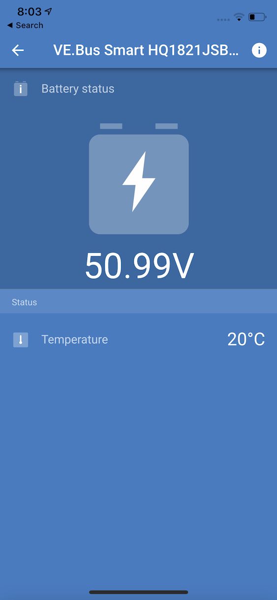
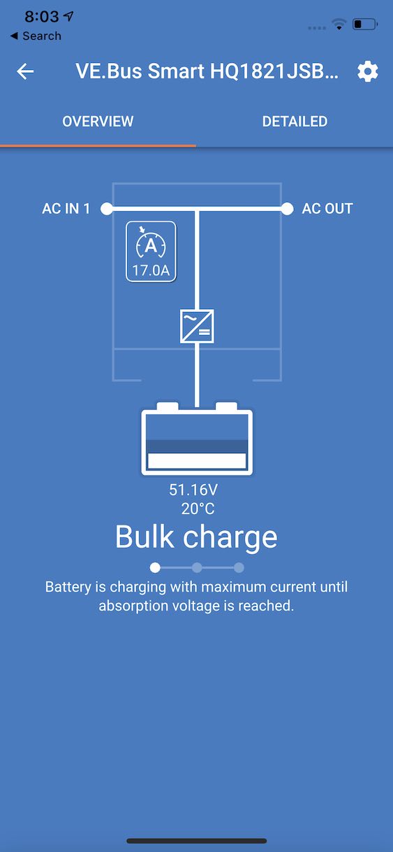
Victron Connect Screenshots
Troubleshooting
See both the VictronConnect manual and the VE.Smart Network manual.