 Add this page to your book
  Remove this page from your book
  Manage book (
 Help
Help This is an old revision of the document!
Table of Contents
Energy Meter ET340 manual
1. Introduction and usage
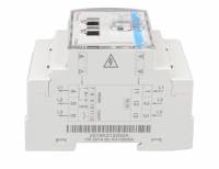
This document is the manual for the 3 phase max 65A per phase Energy Meter.
The Energy Meter can be used for four things:
- Grid meter, and used as control input for an ESS System (1).
- Measure the output of a PV Inverter
- Measure the output of a AC Genset
- (deprecated)
Grid meter, used as control input for a Hub-4 system
The meter is connected to the Color Control GX. There are two options in its wiring:
- Direct connection, either using the RS485 to USB interface with 1.8m cable length, or the 5.0m cable.
- Wireless connection via Zigbee
Note that this model is not stocked by Victron Energy, we recommend to purchase it locally.
2. AC Wiring
3-phase diagram:
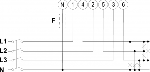
When used to measure a PV Inverter, terminals 1, 2 and 3 should face the PV inverter to ensure correct direction of current and power.
Single phase dual function diagram:
In this diagram, a single meter is used to both measure the grid and a single phase PV Inverter.
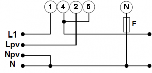
On the CCGX go to the grid meter in the Wired AC sensor settings. Make sure 'Phase type' is set to 'Single phase' and 'PV inverter on phase 2' is enabled.
3. Connection to CCGX
Option A: wireless Zigbee connection
Step 1.
Connect the Zigbee to USB converter to the CCGX using the supplied USB cable. A few seconds after connecting, the active LED should be on and the TX/RX LED should be blinking (the converter takes its power from the CCGX, so the CCGX needs to be switched on as well).

Step 2.
Connect the Zigbee to RS485 converter to the ET340 energy meter:
| Zigbee Converter | Energy meter |
|---|---|
| GND | Terminal 10 |
| A | Terminal 8 |
| B | Terminal 9 |
Step 3.
Make sure only one Zigbee device is powered up right now: the Zigbee to USB converter connected to the CCGX. Power down all others. If you don't do this, the Zigbee to RS485 converter may be connected permanently to another Zigbee device.
Step 4.
Connect the 12V DC power supply to the Zigbee to RS485 converter. When the power is switched on, check the LEDs again.
Option B: Wired connection to CCGX
Connect the Energy Meter to the CCGX using the USB to RS485 cable. The RS485 to USB interface cable between the CCGX and the Energy Meter can be extended up to 100 meters; make sure that the extensions of the Data+ (orange) and Data- (yellow) wires form a twisted pair.
| RS485 Converter | Energy meter |
|---|---|
| Yellow (Data-) | Terminal 9 |
| Orange (Data+) | Terminal 8 |
| Black (GND) | Terminal 10 |
The red, green and brown wire coming out of the USB to RS485 cable are not used.
3. Configuration
After proper connection and powering up, the meter will be visible on the CCGX in the Settings → Energy Meters menu:
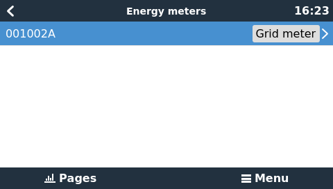
The menu lists every meter found. And in the gray box at the right side it shows the configured function.
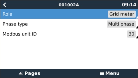
After selecting a meter, see its detailed settings:
4. Multiple Energy Meters in one system
To connect multiple Energy Meters, wire each meter to a separate RS485-USB converter. Which are then each plugged into a separate USB socket on the CCGX.
Connecting multiple ET340 meters to the same RS485-USB cable is not possible: the ET340 meter has no display and its Modbus address can therefor not be changed.
DISQUS
~~DISQUS~~