 Add this page to your book
  Remove this page from your book
  Manage book (
 Help
Help This is an old revision of the document!
Table of Contents
Lynx DC distribution system
The lynx system is a modular DC bus bar system used to connect batteries, DC equipment and provide fusing and battery monitoring. It consists of the following modules:
You can use the Lynx Distributor or Lynx Power In with or without the Lynx Shunt.
Information on these 3 parts can be found below, but also in this manual

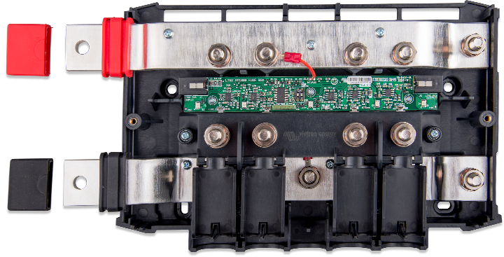
Lynx Power in

The lynx power in module is used to connect batteries via an external fuse. It can be useful if you have multiple parallel strings. Due to the extremely high short circuit current potential of most battery banks, it is suggested to use an external fuse system with an appropriate fault current interruption rating (such as an NH HRC).
The Power In contains a negative and positive DC bus-bar with M8 bolts in which to connect batteries cables. It can take cables up to 22 mm in diameter through the bottom entry guides, and no limit via the two side connections.
Lynx shunt

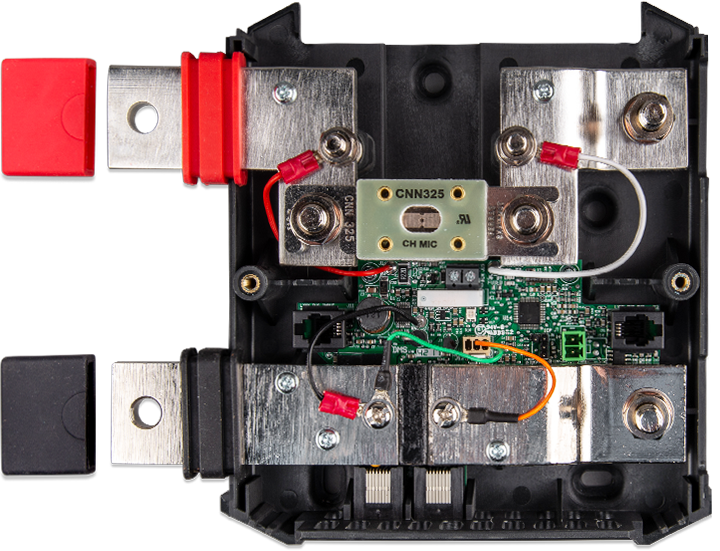
The Lynx shunt contains a positive bus-bar with space to mount a CNN fuse and a negative bus-bar with a shunt. It also contains battery monitoring electronics. The Lynx shunt can send via the VE.CAN bus battery monitoring information to a CCGX or VGX or to a third party CANbus monitoring system, such as a NMEA2000. The CCGX, VGX or third party display acts as battery monitor display and is also used to set up the built-in battery monitor.
The Lynx shunt is available with a VE.Can connection. A previous model had a VE.Net connection and is now discontinued.
Fuse
CIP140325000 - Fuse CNN 325A/80V for Lynx shunt
Or alternatively a CNN fuses by Littlefuse can be used. The CNN fuse is a 48 Vdc fast blow fuse and is available up to 800A.
Shunt
Rated at 1000 A
Setup
Setup is like setting up a BMV and this is done via the CCGX or VGX.
To find out the meaning of the various settings, please see the BMV manual
Please don’t use the 2-pin terminal block on the Lynx-shunt.
FAQ
Q - Is there a way of setting the battery instance?
A - There is a program available to change this but as the default is 0, which is the same as what a CCGX reads we would not advise changing this!!
Further Questions and Answers about the Lynx Shunt are available on the Victron Community topic.
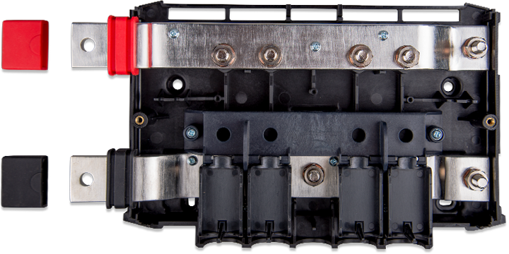
Lynx Distributor

Contains a positive and negative bus-bar and provides a connection for 4 individual DC equipment circuits, loads or DC groups. It has a space for individual DC fuses per DC group.
There is an optional feature of an LED for each fuse to indicate if fuse is blown.
If you wish to use the fuse indication LEDs on the Lynx Distributor, it also requires a connection to a Lynx Shunt. The Lynx Shunt contains the necessary wide input (8 to 70VDC) power supply to output the required 5V (4,5V-5,5V) power requirement of the Lynx Distributor circuit board.
RJ11 fly leads are used to connect the Lynx Shunt to the Distributor. This RJ11 cable is supplied with the Distributor in the box. There are two ports on the Lynx Shunt, and it is possible to use either.
When all is OK, only the central LED is green; when a fuse has blown (or is missing) the central and blow fuse circuit LEDs turn red. If you are not using all connection points in your DC distribution, it may be necessary to fit dummy fuses to extinguish the red LEDs.
Fuses
Uses MEGA fuses. Please note that some MEGA fuses are only rated to 36Volt (suitable for 24V systems), You must use 58/64V rated fuses for 48V systems.
Installation
Connectors and dip-switches:
- The R11 connector is to power the Lynx-distributor from the Lynx-shunt
- The DIP switch on the Lynx-distributor are for specific manual settings, to do with our 24V batteries. Please don’t touch.
- The 6-pin header block on the Lynx Distributor is for reading out the fuses, but this feature is not supported.
FAQ
Q - There is a small 4-pin cable shipped with the Distributor - I can only assume that the cable interconnects between the Shunt and Distributor?
A - Yes, but this has only to power the LEDs on the distributor, there is no other function for this at the moment.
Q - The Distributor has a DIP switch. What are the settings?
A - That’s for manual settings, please don’t touch as the system will auto configure (up to 32 battery’s )
Why Fuse the Bus?
Batteries are special. They are both a source and destination of energy.
Power can flow from them to a load (or a fault). It can also flow to them from a charge source (eg other batteries or solar).
It is important that in cases where batteries are combined, and there is the opportunity for current to flow from one connection to another in fault, that there is sufficient and robust circuit protection.
For example, the BYD Lithium IP55 cabinets.
In this case the 4 module battery cabinets are each protected by individual 85A circuit breakers and also collectively protected by a 125A circuit breaker at the cabinet end.
These cabinets are then connected through the Lynx Distributor, and those main battery take off wires are connected at the Bus end by another 125A MEGA fuse.
Both the 125A circuit breaker and the 125A fuse are as close as possible to their respective sources of current. The battery cells, where the internal wire is protected inside the cabinet. And the shared bus bar (where current can flow from other batteries or a charge source).
This means that if there is a short circuit fault somewhere along the battery cabinet take off cable, there is sufficient protection.
Without the 125A bus bar MEGA fuse. There is the possibility of the battery take off cables fault that the 125A cabinet circuit breaker trips, but that the fault is continued by the supply of the other batteries (up to their combined 375A) and this exceeds the current rating of the cable to the fault and starts a fire.
This is an unlikely scenario, but consequences of a fire in an energy storage situation are so serious that it is a recommended level of protection.
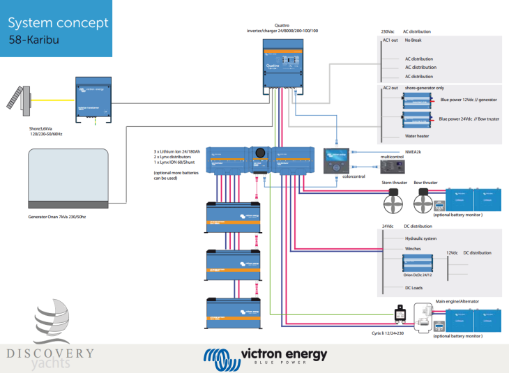
Customer Images
Here are some images from customer's installations that may help you to understand the installation of the Lynx System.


Ysebaert's Hybrid Back-up System in Belgium

AMSolar's 2015 Redwood 38RL, 42’
