 Add this page to your book
  Remove this page from your book
  Manage book (
 Help
Help This is an old revision of the document!
Table of Contents
Wireless AC Sensor manual (draft)
Introduction
The Wireless AC sensors are used to measure PV Inverter power (A) and energy (kWh), and show it on a Color Control GX and the VRM Portal. An installation will have one gateway, and one sensor per phase. The gateway connects to the Color Control via Ethernet, and is the DECT hub for the sensors.
[mco: Spanning (V) en stroom (A) worden gemeten. Power (W) en energy (kWh) worden berekend. Zal ik dit hierboven aanpassen? Wil je ook al noemen dat het voor de Hub4 assistant gebruikt zal worden?]
[ add measurement accuracy etc. or at the end of this doc. ] [mco: hebben we deze info. Ik weet alleen rating zoals die op de sticker op de zijkant staat]
Required hardware
- TIM000100100 - Wireless AC sensor 25A (one for each phase)
- TIM000100000 - Wireless Sensor gateway (one for every system)
Included with the gateway:
- 30cm RJ45 cable 30cm
- AC adapter
 Note that instead of powering the Wireless Sensor gateway with the AC adapter, it is also possible to power it from one of the USB ports in the Color Control GX. Purchase a separate male Micro-USB to male USB cable, not available from Victron. (note, it is not yet sure if the CCGX can supply enough power, we are currently testing this.) [mco: voor alleen de Wireless gateway is stroomverbruik geen probleeem]
Installation
Installing the gateway
- Disconnect the AC power
- Connect the gateway to the network using the supplied RJ45 cable.
- Connect the AC power adapter to the gateway
Installing the sensor(s)
For each phase, connect the AC sensor according to the schematic below. Neutral on top side. Line on bottom side. Make sure the direction of the current is correct

Gateway and sensor pairing
After powering the sensor for the first time, it needs to be paired with the gateway. The led on the sensor will be blinking red, to indicate that it is not yet paired to a gateway.
If it is not blinking red, but both the green and the red LED are on, it needs to be unpaired first: press and hold the little reset button in the sensor. As soon as you press the button the LED will turn green. Hold the button until the LED starts blinking red.
To let the gateway search for and pair with free sensors, press the button on the gateway for 5 seconds. The led on the gateway will start blinking red. First slow then both leds (gateway and sensor) will start blinking red fast. If sensor is found the led will shortly blink orange.
The discovery will take anywhere between 30 seconds and 12 minutes. The 12 minutes can be because of a software update.
When the update process is completed then the sensor LED will be off, and the gateway LED will be green with short intermittent blips of red.
Gateway LED
| LED | Meaning |
|---|---|
| Blinking red | Searching for sensors |
| Green with short blips of red | Working OK |
Sensor LED
| LED | Meaning |
|---|---|
| Blinking red | Not yet paired to a gateway |
| Both green and red on (no blinking) | Cannot find the gateway |
| Alternating red/green | Selected in the Color Control menu, useful for identification |
| Green on (no blinking) | Gateway found, connecting. This will show only for a few seconds |
| Off | Working OK, connected to the gateway, or not powered |
Configuration on the Color Control
Wireless AC sensor menu
To configure the gateway and sensor go to the Wireless AC sensor menu
Settings → Wireless AC Sensors
If the gateway is connect to the network it will be shown in the list. If one or more AC sensors are connected these will also show in the list.
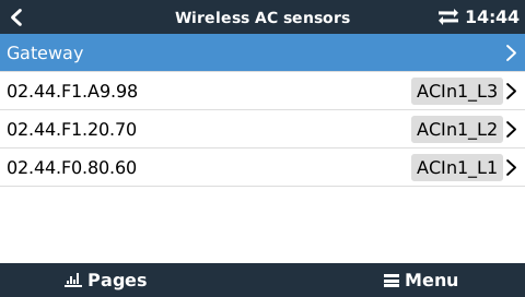
Now the AC sensor will be visible in the Wireless sensor menu on the ColorControl. Go in to the menu to assign a location of the sensor. For example ACOut_L1. After this the led will blink and turn green.
~~DISQUS~~