 Add this page to your book
  Remove this page from your book
  Manage book (
 Help
Help This is an old revision of the document!
Table of Contents
Victron & BYD B-Box
The combination of Victron products with BYD Battery-Box LV lithium batteries has been tested and certified by the Victron and BYD R&D departments. This combination has extensive field experience and is actively supported by both companies.
The BYD B-Box includes an integrated Battery Management System (BMS) with each battery cell module, and a Battery Management Unit (BMU) that interfaces with the Victron GX device and supports multiple battery modules.
| Battery | Pro 2.5-10.0 | Pro 12.8 & 13.8 | L 3.5-14.0 | Premium LVL 15.4 |
|---|---|---|---|---|
| Appearance | 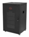 | 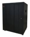 | 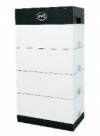 | 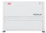 |
| ESS | yes | yes | yes | yes |
| Grid Backup | yes | yes | yes | yes |
| Off-Grid | yes | yes | no | yes |
| Module capacity | 2.5 kWh | 13.8 kWh | 3.5 kWh | 15.36 kWh |
| Module limit | 32 | 32 | 12 | 64 |
| Max capacity | 80 kWh | 441.6 kWh | 42 kWh | 983 kWh |
1. Product & System compatibility
1.1 Offgrid, Backup and Energy Storage Systems are possible
Victron + BYD B-Box can be used for the following system types:
- Energy Storage Systems - Self Consumption (ESS - Start page)
- Grid Backup
- Off-grid
1.2 A GX device is required, eg Cerbo GX, Color Control GX (CCGX), Venus GX (VGX), etc
It is essential to use the BMS-Can (or CAN-bus) connection of a GX device with the BYD batteries for the keep-alive signal, communication of charge and discharge limits, error codes and state of charge.
When used with B-Box Pro series batteries, the minimum supported firmware version for the GX device is v2.42. When used with B-Box Premium LV series, the minimum supported GX device firmware version is v2.52. It is recommended to use the latest firmware version on new installations and when trouble shooting issues.
1.3 All 48V Multis, MultiPlusses, MultiGrids and Quattros are compatible
The minimum supported firmware version is 469. Updating to the latest firmware is recommended for new installations, and troubleshooting issues.
These inverter/charger units must be connected to the GX device via the VE.Bus connection port.
In grid connected systems, advanced control functions are configurable in the ESS settings on the GX device.
In off-grid systems, the control functions of the BYD Battery Management System (BMS) are built into the latest version of the GX device.
1.4 Solar Charger compatibility
All 48V BlueSolar and SmartSolar VE.Direct MPPT Chargers are compatible (*).
Some of our Solar Chargers feature a VE.Direct communication port, some feature a VE.Can communication port, and some feature both. Both of these types of communication ports can be used to connect the Solar charger to the GX Device. Such connection is mandatory, because it is used to regulate charge currents and voltages.
When planning to use the VE.Can communications port to connect the Solar Charger(s), make sure to select a GX Device that has sufficient CAN-Bus ports. The Color Control GX has only one such port, its VE.Can port, and is therefor not suitable. All other GX Devices can be used, since they have two ports. One can then be used to connect the BYD battery, and the other to connect the Solar Charger.
(*) with exception of the models “BlueSolar MPPT 150/70 CAN-bus” and “BlueSolar MPPT 150/85 CAN-bus” which are end-of-life since 2019. Legacy systems, historically installed with this configuration using the allow to charge contacts are not required to make any changes, see the legacy chapter below for details.
1.5 Battery compatibility
The following batteries are supported:
| B-BOX LV series type |
|---|
| B-BOX Pro 2.5-10.0 |
| B-BOX Pro 12.8 |
| B-BOX Pro 13.8 |
| B-BOX Res 2.5-10.0 |
| B-BOX Compact |
| B-BOX L 3.5-14.0 |
| B-BOX Premium LVL 15.4 |
BYD also releases firmware update for their BMU and BMS.
B-Box Pro BMU Firmware versions earlier than V4-13 are not compatible with Victron equipment and can cause the battery to not be detected.
Minimum BYD firmware version for B-Box Pro: BMU_V2_V4-13_15-Mar-2017. On-screen, or via Remote Console on the GX device, this version is named v4.13. Batteries with older firmware versions can be updated. Please contact BYD for more information.
BYD Premium LVL batteries firmware should be no less than V1.4, and the BMS firmware should be no less than V1.3. If necessary, this can be updated automatically via the ethernet port on the BMU when connected to the internet.
2. Minimum Battery Sizing
The following information is provided by BYD, it is reproduced here for your convenience and should always be confirmed with the latest BYD manuals and specifications.
Each B-Box Pro 2.5 battery module is approximately 50Ah at 48V (51.2V nominal).
The following charge rates are managed automatically by the BYD BMU and GX device. Temperature effects on charge rates should be considered in the design stage in hot and cold climates.
Using very large solar arrays with battery banks that are too small can exceed the limits of the batteries ability to charge and possibly lead to the BMU triggering over-current alarms.
The table below shows the minimum number of battery modules required for the specified inverter/charger configuration:
Battery Modules Required - Pro 2.5
| Phases | Single Phase | Three Phase | Single Phase | Three Phase |
| Inverter/Charger | Self-consumption | Self-consumption | Off-grid | Off-grid |
| Multiplus 48/3000/35 | 1 | 3 | 2 | 6 |
| Multiplus 48/5000/70 | 1 | 3 | 3 | 9 |
| Quattro 48/5000/70-100/100 | 1 | 3 | 3 | 9 |
| Quattro 48/8000/110-100/100 | 1 | 4 | 5 | 15 |
| Quattro 48/10000/140- 100/100 | 1 | 5 | 6 | 18 |
| Quattro 48/15000/200- 100/100 | 1 | 6 | 9 | 27 |
| EasySolar 48/3000/35-50 MPPT150/70 | 1 | 3 | 2 | 6 |
| EasySolar 48/5000/70-100 MPPT150/100 | 1 | 3 | 3 | 9 |
Battery Modules Required - Pro 12.8 & 13.8
| Phases | Single Phase | Three Phase | Single Phase | Three Phase |
| Inverter/Charger | Self-consumption | Self-consumption | Off-grid | Off-grid |
| Multiplus 48/3000/35 | 1 | 1 | 1 | 2 |
| Multiplus 48/5000/70 | 1 | 1 | 1 | 3 |
| Quattro 48/5000/70-100/100 | 1 | 1 | 1 | 3 |
| Quattro 48/8000/110-100/100 | 1 | 2 | 2 | 5 |
| Quattro 48/10000/140- 100/100 | 1 | 2 | 2 | 6 |
| Quattro 48/15000/200- 100/100 | 1 | 3 | 3 | 7 |
| EasySolar 48/3000/35-50 MPPT150/70 | 1 | 1 | 1 | 2 |
| EasySolar 48/5000/70-100 MPPT150/100 | 1 | 1 | 1 | 3 |
Battery Modules Required - L 3.5
| Phases | Single Phase | Three Phase | Single Phase | Three Phase |
| Inverter/Charger | Self-consumption | Self-consumption | Grid-backup | Grid-backup |
| Multiplus 48/3000/35 | 1 | 2 | 2 | 6 |
| Multiplus 48/5000/70 | 1 | 2 | 4 | 10 |
| Quattro 48/5000/70-100/100 | 1 | 2 | 4 | 10 |
| Quattro 48/8000/110-100/100 | 1 | 3 | 5 | x |
| Quattro 48/10000/140- 100/100 | 1 | 4 | 7 | x |
| Quattro 48/15000/200- 100/100 | 1 | 5 | 10 | x |
| EasySolar 48/3000/35-50 MPPT150/70 | 1 | 2 | 2 | 6 |
| EasySolar 48/5000/70-100 MPPT150/100 | 1 | 2 | 4 | 10 |
Minimum discharge SOC for 1 single Battery Box L 3.5 is 12%; for 2 or more (7kWh+) it can be 10%.
Up to 4 L modules can be installed per L series BCU; 5 or more will require additional BCU.
Battery Modules Required - Premium LVL 15.4
| Phases | Single Phase | Three Phase | Single Phase | Three Phase |
| Inverter/Charger | On-Grid \ with Full Backup | On-Grid \ with inrush | Off-grid | Off-grid \ with inrush |
| Multiplus 48/3000/35 | 1 | 1 \ 2 | 1 | 1 \ 2 |
| Multiplus 48/5000/70 | 1 | 2 \ 2 | 1 | 2 |
| Quattro 48/5000/70-100/100 | 1 | 2 \ 2 | 1 | 2 |
| Quattro 48/8000/110-100/100 | 1 | 2 \ 3 | 1 | 2 |
| Quattro 48/10000/140- 100/100 | 1 | 3 \ 4 | 1 | 3 \ 4 |
| Quattro 48/15000/200- 100/100 | 1 \ 2 | 4 \ 6 | 2 | 4 \ 6 |
| EasySolar 48/3000/35-50 MPPT150/70 | 1 | 1 | 1 | 1 |
| EasySolar 48/5000/70-100 MPPT150/100 | 1 | 2 \ 2 | 1 | 2 |
“With inrush” - this is the advice for systems that have load profiles that use the full surge capacity of the inverter, eg Multiplus 48/5000/70 providing 10 kW for 5 seconds to start an electric motor.
The specification for these minimum battery sizes was obtained from BYD’s 2018 minimum specification guide. There is an additional guide here for the 12.8 and 13.8 models, and here for the Premium LVL 15.4 model.
3. CAN-Bus wiring between the battery and GX Device
Use the VE.Can to CAN-bus BMS type A Cable, part number ASS030710018. Plug the side which is labeled Battery BMS into the BYD BMS. Plug the side labeled Victron VE.Can into the GX device.
Then, plug a VE.Can terminator in the other VE.Can socket on the GX device. Two VE.Can terminators are included with the package of the GX device as an accessory, only one is used. Keep the other one as a spare.
More information about the cable can be found in its manual.
Without properly connecting this cable, the battery will not show up on the display of the GX device. The battery will also turn itself off after several minutes.
It is important to ensure this connection and display of the battery on the GX device display before attempting firmware updates or settings changes on other devices if they depend on the power supply from the battery. Without this connection, the battery may turn off unexpectedly. If a reliable DC power supply is required, you can temporarily disconnect the individual BYD battery cells inside their cabinet from the internal Battery Management Unit (BMU). It is the BMU that signals the battery cells to shut down if the signal from the GX device has not been received. This is a temporary measure, DO NOT attempt to operate the battery cells normally without connection to the BMU.
4. VEConfigure settings
This section presumes familiarity with VEConfigure software.
4.1 General tab
- Check the “Enable battery monitor” function
- Set the battery capacity to the total capacity of the battery: eg 50Ah times the number of battery modules for the 2.5 model.
- The other parameters (“State of charge when bulk finished” and “Charge efficiency”) can be left to their default setting: They are ignored for a BYD installation.
4.2 Charge parameters
In normal operation, the charge parameters are controlled by the BYD BMU and communicated through the system by the GX device to the inverter/charger and MPPT. However as a precaution it is advised to set these as suggested below.
Charger tab
| VEConfigure Charge Parameter | Setting |
|---|---|
| Battery type | Lithium |
| Charge curve | Fixed |
| Absorption voltage | 55.2 V |
| Float voltage | 55 V |
| Absorption time | 1 Hr |
Note: make sure to double check the float voltage after completing Assistants, and if necessary set it back to 55 V.
4.3 Inverter Settings
In the Inverter tab of VEConfigure
| VEConfigure Inverter Parameter | Setting |
|---|---|
| DC input low shut-down | 47V |
| DC input low restart | 51V |
| DC input low pre-alarm* | 51V |
* The pre-alarm setting is dependant on your preference and on site specific requirements. You may wish for this to be activated earlier (eg 53V) in an off grid situation to allow time to start a backup generator. If the system is configured in ESS mode, you may not wish to have this alarm trigger until below the Sustain threshold voltage (eg 49V), as this system is in no danger normally and will 'sustain' at 50V without needing to trigger an alarm.
ESS System Settings
If you are using the battery as part of a grid connected ESS system, please review the ESS Quickstart guide and Design and Installation Manual.
The settings that are specific to the BYD battery in the VEConfigure ESS Assistant are below:
Select the externally managed Lithium battery option
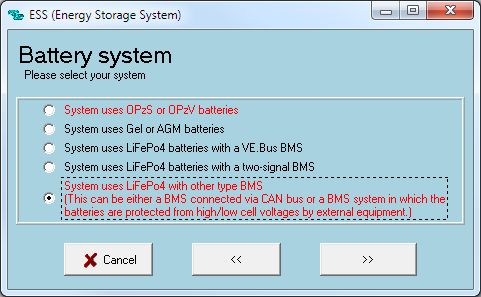
| ESS Parameter | Settings |
|---|---|
| Sustain voltage. | 50V |
| Dynamic cut-off values | set all values to 47V. |
| Restart offset: | 1.2 V (Default) |
5. GX device configuration
On the GX device, go to Settings, System setup:
| Venus Settings → System Setup Parameter | Value |
|---|---|
| DVCC | ON |
| Shared Voltage Sense | OFF |
* Select the CAN-bus BMS (500 kbit/s) CAN-profile in the CCGX. Menu path: Settings → Services → CAN-profile.
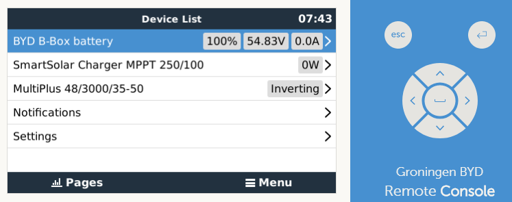
- After properly wiring and setting up, the B-Box will be visible as a battery in the device list:
 (if you have multiple batteries a single entry will show up, which represents all batteries).
- The parameters option within the battery page shows the actual battery charge and discharge limits

This parameters page is also a good place to check that all batteries are connected and working properly. In normal working conditions, for the 2.5 model, the charge current limit is ~35-50 A per cell. For example, 140A charge current limit ( 140 / 35 = 4 ) means there are 4 BYD battery cells connected.
Note these limits have been adjusted higher by BYD during firmware updates, so the charge and discharge current limit figure may appear slightly higher.
Color Control GX Configuration
The CCGX only has one available VE.Can port. It is not possible to connect both CAN products such as VE.Can MPPT (250 kbit/s) and an B-Box battery CAN-bus (500 kbit/s) together on the CCGX. As the BYD Battery MUST be connected, you will need to use the port for that. This will mean no data is collected from the VE.Can MPPT, nor can the CCGX control it. This means you are required to use the “Allow to Charge” wire configuration for the MPPT.
GX Device with multiple CAN-bus port configuration
With GX devices that have two CAN-bus interfaces available (eg Cerbo GX and Venus GX), the VE.Can MPPT will remain connected to the VE.Can port, while the BYD CAN-bus cable should use the specific CAN-bus connections (H, L, GND), or BMS-Can ports.
This allows data from the MPPT and BYD battery simultaneously.
The CAN-bus connections are galvanically isolated at the BYD BMU. There is no issues using the non-isolated connection of the VGX.
6. Solar Charger configuration
The MPPT charge characteristics are automatically configured & governed by the GX device. The settings below are a precautionary measure only:
| MPPT Parameter | Setting |
|---|---|
| Battery voltage | 48V |
| Absorption voltage | 56.5V |
Use VictronConnect for Solar Charger configuration.
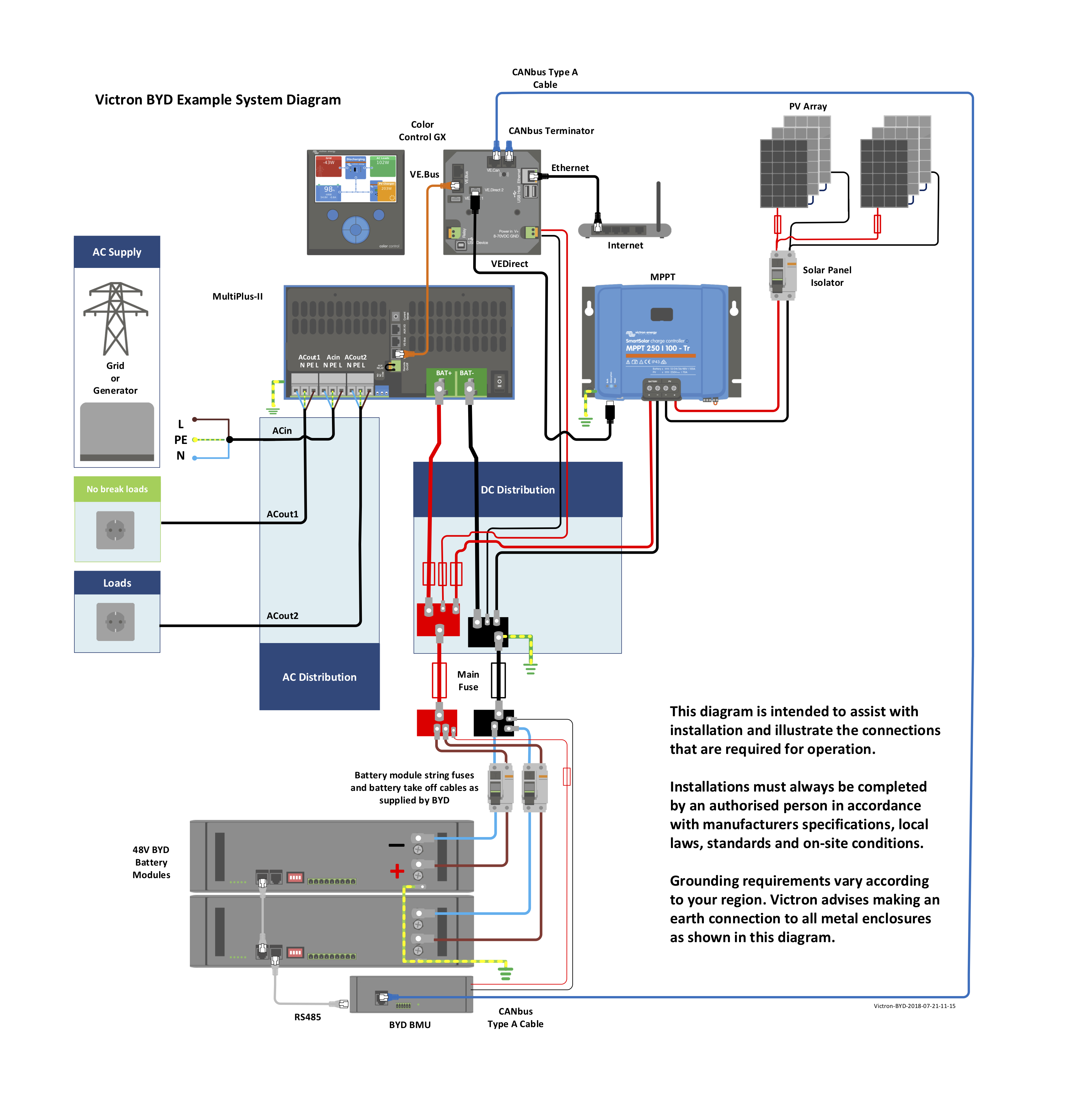
7. Example Wiring Diagram
8. Troubleshooting
If the system is not operating correctly, go through these steps.
Step 0. If the Inverter/Charger or GX device does not switch on
As a safety precaution, the inverter/charger will not switch on if the GX device is not on. If you are unable to start the system due to a total system blackout / battery shutdown due to low voltage, you may need to disconnect the VE.BUS connection cable between the inverter/charger and GX device.
You can then start the inverter/charger from an external charge source such as a generator or grid connection. Once the inverter/charger has started, it should supply power to the DC terminals and this should start the GX device and BYD battery again. You will need to then reconnect the VE.Bus Communications cable back to the inverter/charger and GX device.
Step 1. Check that the BYD battery is visible on the GX device list
If its not visible, check:
- GX device firmware version (update to latest version, v2.15 or later)
- BYD firmware version (see requirement above)
- CAN-bus communication cabling between BYD and Victron system. Make sure that it is in the right way around. If the special cable is plugged in reversed it won't work.
- BYD system is up and running (RUN led on BYD BMU is on)
Step 2. Check that the BYD battery is ready for use
Check the Max Charge Voltage parameter. This voltage parameter is sent, together with the other three parameters, by the BYD system via the CAN-bus cable. They are visible on the GX device: Device List → BYD B-Box battery → Parameters menu.
When ready for use, the Max Charge Voltage will read 56.5 V. In case there is an error in the BYD system (wiring, addressing, or other), it will be 42 V:

Also check that your are seeing the expected 35-40 A of discharge current per installed module.
Locally on-site, you can check the Run LED on the BYD BMU, it needs to be lit up continuously:
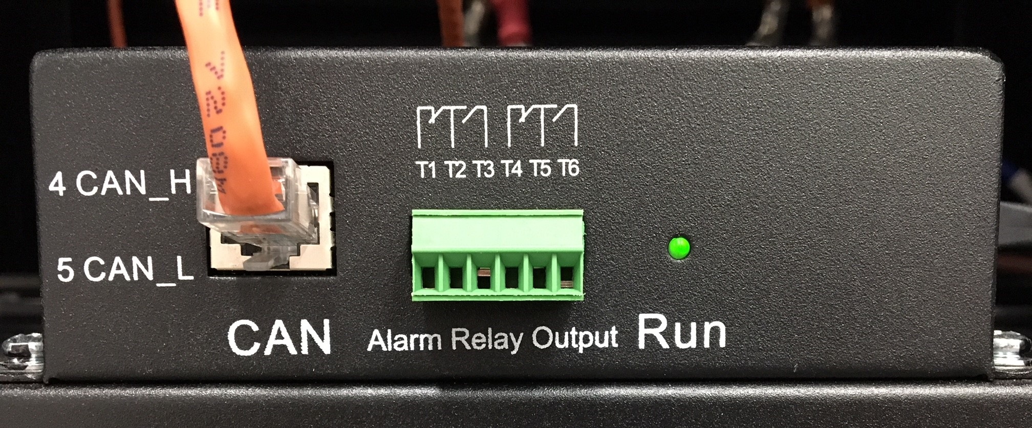
A blinking RUN led indicates an error. On the Victron system this is visible as a Max Charge Voltage of 42 V instead of 56.5 V.
- BMU led blinking once every time, focus on the communication with the inverter
- BMU led blinking more than once (2, 3 or 4 times) focus on the ADDR and communication (cables) between batteries and BMU.
- Battery module SOC LED scrolling side to side: review the ADDR and check/replace the communication cables leading to that battery
Addressing of the battery modules must start at 1, must be continuous and there may not be two modules with the same address. See BYD documentation for details.
In case above doesn't help, and the battery indicates 42V and/or the RUN led is not blinking continuous, please contact BYD support or refer to BYD documentation.
Restarting the BYD system
Restarting the BYD system is always necessary after adding, or removing, battery modules from the system. It may also be necessary to clear some severe error conditions.
To power down a battery module: one by one, push the reset button on the Battery Module for 5 seconds, until the yellow ARM LED flashes. Once releasing the button, the ARM LED will keep blinking for a few more seconds and then all LEDs switch off on the battery module.
Once all battery modules are powered down, the BMU will shut down also: RUN LED is off.
To power up: one by one shortly press the reset button on the battery modules.
It might be that after power up one or modules will light the ARM (Alarm) LED continuously for a short while. Wait for this to auto-correct itself.
In general the ARM LED on the battery module has these meanings:
- Could be a temporary issue, that corrects self automatically after a short while (matter of minutes).
- Could be an external issue, unacceptable voltage or current.
9. Step by Step Installation Guide
There is a step by step installation video that demonstrates the essential connections and programming that is required for installation of a BYD battery in a Victron system. It is accessible via the E-Learning section in Victron Professional, and a free Victron Professional Installer Account is required.
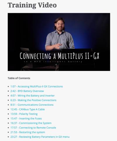
This written manual should be assumed to be the more accurate and up-to-date, if there are any discrepancies between the video and the written manual,
A user contributed step by step installation guide is available here. Please be aware that this guide is no longer current. It should not be considered a best practice, but provides further detail and insights from an actual installation.
10. Known Issues
10.1 Inaccurate State of Charge (SoC) Readings
Each BYD battery module has it’s own BMS. This BMS reports it’s battery information to the BMU which is connected to the GX device and reported to the user and the system.
Each BYD module BMS has a threshold current of 1A (~50W) before it begins to report. For multiple modules, this is additive. So 4 modules could supply a 180W load and report it as 0 W.
This leads to the state of charge reported by the BMU to not accurately match the actual state of charge of the battery.
This limitation also applies to charge currents as well as loads. However it is more common to have low powered loads for long periods of time than low charge currents.
The reported State of Charge will self correct when it reaches the calibration voltage point (55.2v ~ 100% full) or near 10% empty, and this can appear as sudden jumps in the VRM from very little load or charge.
This has no impact on actual usable capacity of battery, only on the how it is reported to the user and other systems (such as alarms or triggers).
Work-arounds
If precise state of charge is important, it is possible to install a Victron BMV shunt, and program the GX device to use it for the displayed State of Charge. The limitations of this method are if cells are added, removed or shut down, the BMV will continue to report SoC based on the total Ah of storage set.
You should have alarms and auto-start generators programmed to operate on system voltage as well as state of charge.
System voltage is always reported accurately, and action should be taken once batteries are below 50V for any length of time,
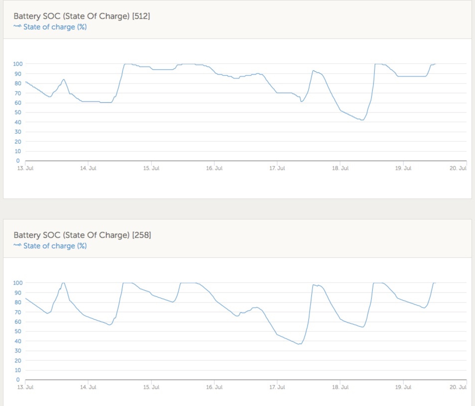
Example
This example below clearly shows the comparison between a BYD BMU (512) and the shunt reading that is reported by the BMV-700 (258).
You can observe a ‘flat’ reading from the BYD during the night, while the BMV continues to read the discharge and report a slowly decreasing state of charge.
10.2 125A cabinet limit
The IP55 BYD cabinets are designed to take 4 battery modules and are supplied with 125A circuit breakers. Each battery module is able to supply and receive a continuous 35A, all together a combined 140A. This means it is possible to overload the circuit breaker.
If you have multiple large charge sources, set the DVCC distributed charge current limit to 120A per cabinet to stay under the circuit breaker limit.
If you have a system with multiple cabinets, try to balance the modules evenly between the cabinets to make it less likely to overload the breakers.
Multiple cabinets will also require other circuit protection at the DC bus level.
10.3 Cold Weather Performance
The BYD cells will limit the charge current allowed at lower temperatures.
| Temperature (Celsius) | Charge Current Limit Per Cell | C rating |
|---|---|---|
| 50 to 13 degrees | 35 A | 0.7C |
| 12 to 3 degrees | 6 A | 0.12C |
| 2 to -7 degrees | 3 A | 0.06C |
Keep your batteries in a climate controlled environment as close to 20 degrees celsius as possible for best performance. Depending on your climate, consider insulation and reverse cycle air-conditioning to prevent issues in hot and cold weather.
Cells will also heat themselves up when charged and discharged.
There has been a firmware revision for the BYD battery modules and BMU that improves cold weather performance slightly. This manual will be updated with the new (slightly improved) specifications when stock supplied with the new firmware has had sufficient time to enter the market. Contact your BYD distributor for further information about this.
10.4 Self-Startup from Low voltage shutdown modes
In a correctly configured system, the inverter will shut itself down before the batteries enter a self protective shut down state.
If your system is supplied only with AC-bus solar charging, this may prevent the solar inverter from starting up to recharge the batteries. Therefore it is strongly recommended that there is also either a generator or DC MPPT charge controller to provide DC bus power to bring the inverter back online to allow normal recharging to resume.
Even a single 100/20 48V MPPT charger unit with 2 x 60 cell solar panels would be sufficient to add this self correcting mechanism able to maintain the DC bus voltage and improve longterm system reliability considerably from accidental deep discharge and subsequent shut down.
11. Legacy systems using allow-to-charge and allow-to-discharge contacts
For proper operation, the B-Box battery needs to be able to control the charge current of the solar MPPTs. Which for all modern models is arranged via the VE.Can and VE.Direct digital communication protocols. The very first two BlueSolar Chargers made by Victron, the “BlueSolar MPPT 150/70 CAN-bus” and “BlueSolar MPPT 150/85 CAN-bus” models, do no support such control, and were therefor controlled with a wire: the allow-to-charge wire.
The purpose of this chapter is to serve as reference guide for legacy systems using those two solar charger models. If you have an existing system that is configured using the Allow-to-charge contacts, and it is operating correctly, you do not need to make any changes.
Note that these charges cannot be used with the BYD Premium LV batteries, since they do not feature the required free contacts.
Legacy system wiring details
The Remote On/Off input of the two mentioned solar charger models is used to signal that they can or cannot charge the battery. It needs to be connected to battery positive to enable the charger. Leaving the Remote On/Off input floating or pulling it to ground will disable the charger.
B-Box relays:
- Relay T1-T2: closed if allowed to discharge
- Relay T4-T5: closed if allowed to charge
Picture showing these connections on the BYD B-Box battery:

12. Further Information
For information about where to buy or find suitably qualified installers, visit the Where to Buy Page.
Further community discussion about installing and using BYD and Victron can found at Victron Community, use the topic label 'BYD'.
DISQUS
~~DISQUS~~