So much can be learned from the discussions taking place right now on the Victron Community pages. Subscription is free of course, and you are very welcome to join in.
With credit to John, M Lange and Guy Stewart we thought we would highlight a recent discussion which shines a light onto Photovoltaic panels, and what happens to their voltage and current output in conditions of shade. Here’s what we learned:
Solar panels, unless heavily shaded have a remarkably high and consistent voltage output even as the intensity of the sun changes. It is predominantly the current output that decreases as light intensity falls.
Panel temperature will affect voltage – as has been discussed in another blog.
Have a look at these I-V (Current vs Voltage) and P-V (Power vs Voltage) charts for a 305W solar panel from Trina Solar.
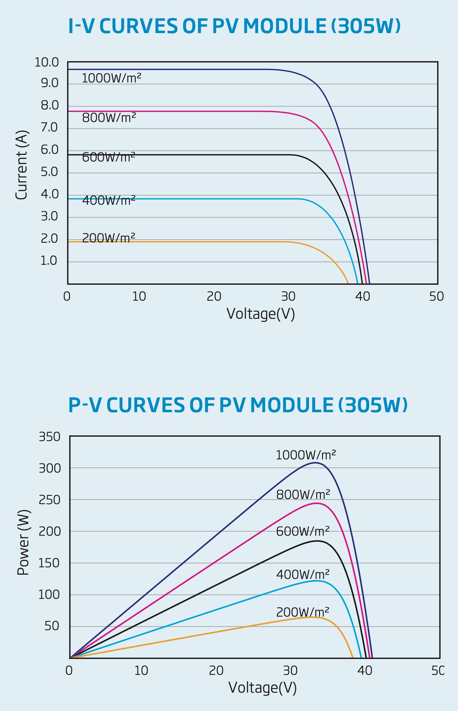
You can see in the P-V curve that as the solar radiation decreases from 1000W/m2 to 200W/m2, the power drops proportionally – from 300W to 60W. The Voltage output range remains nearly constant, however with the Maximum Power Point (MPP) voltage at 33V, and the maximum open circuit voltage only dropping from 43V to 38V.
If the voltage is pretty constant regardless of the intensity of the light, then the Current must be changing. (Note that these tests were all run at 25°C)
You can see this clearly in the I-V curve, where the output current has dropped from 9.8 A at 1000W/m2 to 2 A at 200W/m2.
Clear skies
What this means is that the input voltage in a correctly designed and installed system, with a clear view of the sky, should nearly always be within the acceptable voltage window of the MPPT for optimum performance (even when its cloudy).
Heavy shading from a tree for example – or when panels become extremely hot – DOES affect voltage markedly.
Due to the nature of the semi-conductive silicon in PV cells, the effect of a blocking shade on the solar panel is so severe that if a single cell (of which there can be between 36 and 144 in each panel) is completely shaded, it will completely restrict the flow of electricity through it.
Solar panels have built-in bypass diodes to skip a troublesome cell group (usually several horizontal columns of cells) allowing the energy from the other unshaded cells to flow once more.
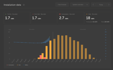
Take a look at GIFs below displaying information from a Victron MPPT – as seen on an iPhone via the free-to-use app VictronConnect – and you will see the relationship between Solar Voltage, and the Battery Voltage. These images are dynamic when clicked:

Now here is the same solar array a short time later when the sun has come out. Notice how the power has increased from ~350W to ~1000W, but the PV Solar Voltage is the same!

The Victron MPPT is a buck DC to DC converter. It reduces the higher PV side voltage to the lower Battery side voltage. It can’t boost the (too low) voltage from a PV panel in order to begin charging a battery.
Working at up to 98% efficiency the MPPT can accept any PV side voltage up to its maximum PV input voltage limit. This varies with the Victron models between 75V and 250V and is clearly printed on the unit itself, and all associated documentation.
On the battery side, it is the battery which sets the system voltage. The MPPT takes the panel voltage and converts it to a charging voltage which is higher than battery voltage in order to get current to flow into the battery, the voltage is reduced, the current goes up, and the power remains the same. But the battery chemistry will be dragging that MPPT voltage down at the DC bus level, and that electrical work is going into the battery chemistry to charge it.
Once the battery is full, and reaches a target voltage, the MPPT will adjust its voltage conversion to maintain a pre-set float voltage which is still higher than the battery voltage at rest – but not high enough to provide a significant current flow …which avoids the battery becoming overcharged.
Bulk, Absorption, Float…
Solar charger output voltage depends on where the connected battery is in its charging cycle (bulk, absorption, float) – the voltage of each stage being pre-set by battery charging algorithm employed by the MPPT. (The target voltage for each step can also be user-defined.)
In the case of a nearly empty lead battery at 11.5V the MPPT begins work by ‘Bulk’ charging with as much power as it can get from the solar panel(s) (unless a lower current-limit has been set) until it reaches the absorption voltage of 14.4V.
The MPPT will only begin charging when there is sufficient solar radiation to cause the PV panel voltage to rise 5V above the Battery voltage. After that condition has been met it will continue charging as long as the PV voltage remains at least 1V higher than the Battery voltage (or until the battery is full).
In the example above: The MPPT will begin charging when the panels provide around 16.5V …and will need a minimum of 12.5 V rising to 15.4V to continue charging.
When planning your installation you may find it helpful to use this ready made solar charging calculator to choose suitably sized equipment.
Panel Voltage consistently lower than expected?
Given that we know PV voltage SHOULD stay consistently high, what can we do if we see an unexpectedly low panel-side voltage in VictronConnect, or using a voltmeter?
The first thing to do would be to physically inspect the panels (if it’s safe to do so) and make sure there isn’t some obvious obstruction. Mould can build up along the bottom edge of a row of flat panels when water isn’t able to drain properly, which reduces the output of the entire array.
If everything looks normal after a visual inspection, check the outdoor terminal connections – these will usually be MC4 connectors which can be separated using an inexpensive specialist tool (or without one – though with greater difficulty). It’s important to make and break these connections only when the panel is under no load – this means either covering the panel to exclude light, or working very early or very late in the day. When the MC4 connector is open it can be visually inspected and any corrosion or oxides cleaned away by spraying the male and female terminals with a Switch or Contact Cleaner. Check the indoor connections too – but not during the day.
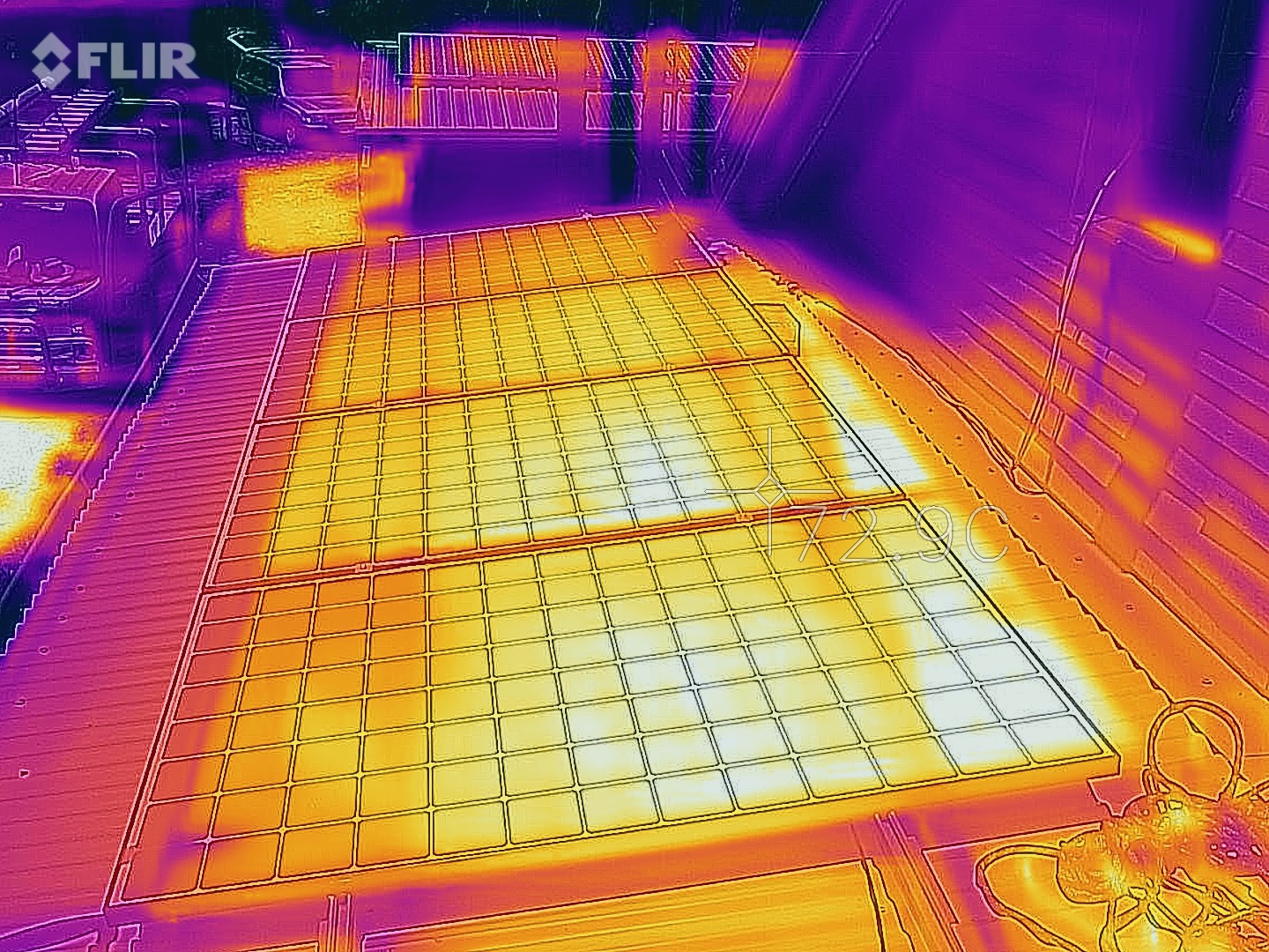
The next level of panel testing uses a thermal camera – but don’t worry, although this requires more specialised test equipment, it is available quite affordably as a mobile phone accessory. Or try calling around solar installers, or electricians. They use them to fault-find on distribution boards. As long as the panel is still connected in the circuit, any resistance to the flow of electricity will show up as heat.
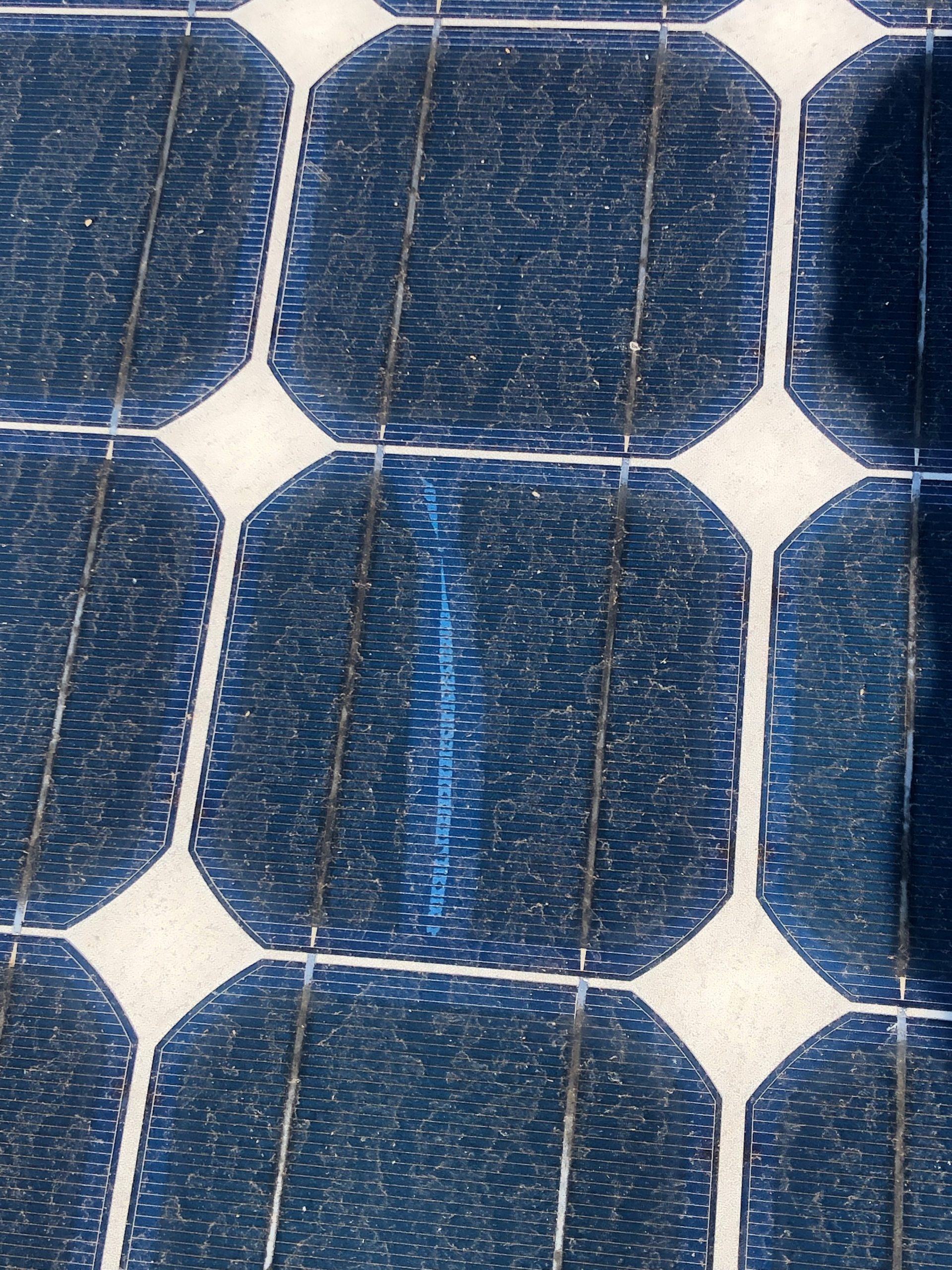
Close inspection can reveal damage, or delamination.

The second image shows a problem where two columns of cells are hotter than those around them. A closer inspection of the cells revealed some cracking and delamination. Depending on the severity, and the cause, it could be panel warranty issue.
The problem could also be on the OTHER side of the panels, where the wiring is connected. Look for anything out of the ordinary: corrosion, melting, marks, or other damage. Be extremely careful; and don’t touch anything without taking the necessary electrical and physical safety precautions.
Please remember that strings of panels generate high voltages which can be dangerous, or fatal. The National Electrical Code (USA) requires all terminals carrying more than 50VDC to be covered, protecting them – well, us – against accidental contact. The code also requires individuals working on circuits carrying more than 100VDC to be trained for that work.
If you have any questions, comments or advice for others on this topic – or any other topic concerning remote energy – why not register onto our community page and join in the discussion? On the Community page your technical question will be answered quickly, by knowledgeable Victron users …and occasionally staff.
(Although we continue to place the DISQUS comment hosting service at the end of each blog, we do so for non-technical comments …as it is not routinely monitored by technical staff.)


