Introduction
In his last article, Josip Zdenković, a Director of SCHRACK TECHNIK Ltd in Croatia, wrote a blog on the use of Victron Energy equipment on board the vessel Matsko. Josip and his team showed precisely how a ‘surgical incision’ could be done in the vessel’s electrical installation to add a quiet power source for times when the noise of generators is undesirable. He promised to describe at least some basic and general rules about the on-board installation in a further article. Here then, in Josip’s own words, is that article. This time assistance was provided by Dalibor Buljan, also from SCHRACK TECHNIK, in producing the pictures. Here is the previous article.
Some details of boat installations
This article is intended as an initial framework for your own research if you decide to self-build or reconstruct your vessel installation. We cannot say everything we want and be sure we have explained all to everyone in a sufficiently clear and precise manner! Do not forget, the people who will use your installation on board are far away from professionals and probably don’t have any special knowledge of using a vessel electrical installation. After studying this article, please consult a certified designer or company that deals with on-board installations daily and has suitably skilled workers. Reading this article does not enable you to work independently without further expert consultation. But perhaps it makes some things a little bit clearer than before…
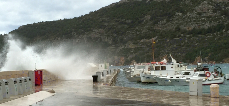
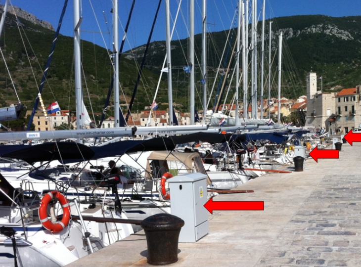
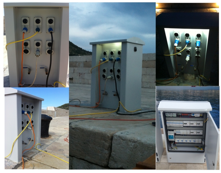
After we tie our boat at the marina or dock, the first thing we want to do is to connect the shore power. Our batteries are probably empty and we have already turned off the refrigerator to save battery power. Ultimately we want to connect to the stronger loads that are not used or needed during navigation. Figure 1 shows boats connected to electrical distributors with terminal box cabinets.
Figure 1 – Dock on Vis Island is equipped with power terminal boxes designed by SCHRACK TECHNIK (same picture as headline image above but taken in summer)
If we want to understand the on-board installation, let’s consider as the first step what we expect to find in the terminal box on shore, according to the standards for low voltage electrical installations, IEC 60364 Part 7-709, describing the requirements for installations in marinas and similar locations. To keep it simple: what kind of protection is expected when using power from the shore socket on the terminal box? Why should all this protection be used?
The effects of current on a human
The most important factor in the effect of electricity on a human is the current strength flowing through the human body, as follows:
- releasing current – the maximum current under which one can separate himself from the live parts, parts under voltage, without help.
- non fibrillation currents – current levels above the releasing current but that still do not cause mortality, and
- fibrillation current – the minimum current which is lethal (its value varies a little for each human).
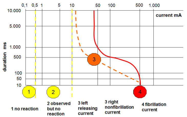
Besides the current strength, duration of exposure has a very large impact, too. Figure 2 shows the reaction zones of a man according to the strength and duration of the current exposed to. Note that Zone 3 is divided by a dashed line into left and right parts.
Figure 2 – Effects on a human caused by the strength and duration of a current
If we want to achieve control over human exposure to electricity, it is necessary to know which level of voltage causes the current flow still permitted and therefore non-hazardous. For normal environmental conditions (dry conditions), the permanently permitted voltage for direct contact of man with live parts is less than 50V at alternating current (AC) 50Hz and less than 120V for direct current (DC). For more difficult environmental conditions (like permanent contact with the live parts by a man who is directly connected to ground potential and with significantly reduced body resistance because of the wet skin or clothes), the contact voltage border is decreased to 25V AC and 60V DC.
If a man is exposed to a mains voltage greater than 50V at 50Hz frequency, for the man’s protection, this voltage level must not last longer than a specified time. For example, while contacting a live part with an AC voltage of 230V at 50Hz, you must not exceed 170 milliseconds (ms) of contact, and in extremely poor, wet conditions, you must not be in contact longer than 50 ms! Of course there are some differences when you consider the exact current path in human body, but this is beyond the article’s scope.
Protection from electrical shock built in the terminal box on the shore
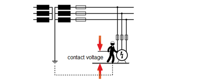
Protection against direct contact with live parts of the energized equipment is performed by installing equipment in closed cabinets and using well-insulated cables. But due to possible insulation failure, the live conductor can still connect to the metal housing or other metal mass, which in normal service is never powered. Then we talk about indirect contact with the live parts, and therefore, appropriate protection against indirect contact is needed. The voltage that appears between simultaneously accessible parts during a failure is called the contact voltage. For example, the expected contact voltage value can be the full voltage level of the supply when the failure is in damaged input cable insulation and the damaged cable is touching the metal appliance housing close to the appliance input terminals and the man is well connected to the ground potential, as shown in Figure 3.
Figure 3 – Indirect contact: an unexpected encounter with live parts – touching the metal housing of defective devices
The usual way to protect a human from indirect contact is by automatic shutdown of the power supply in case of failure. One of the devices for the protection of indirect touch with live parts through automatic shutoff in the terminal box in the marina is the overcurrent protection device. For this device to successfully perform the automatic shutdown of a power supply, a particular failure must cause a strong enough fault current to interrupt the supply at a time that is short enough and therefore non-hazardous for a human.
That means:
- There must be a closed-loop circuit which allows the flow of fault current (the circuitry that runs the fault current depends on the network and load earthing system; i.e., TN, TT, IT; again we will not go more deeply in!).
- The fault current interrupt must happen by using the appropriate overcurrent protection devices in time to prevent injury to someone exposed to a contact voltage.
The overcurrent protection device in the terminal box of the marina is a Miniature Circuit Breaker (MCB). In Figure 4a, a typical cross section inside view of a SCHRACK TECHNIK MCB is given together with switch-off current-time characteristics.
Figure 4a – SCHRACK TECHNIK MCB cross section; switch-off curves of a few MCB types with 32A rating
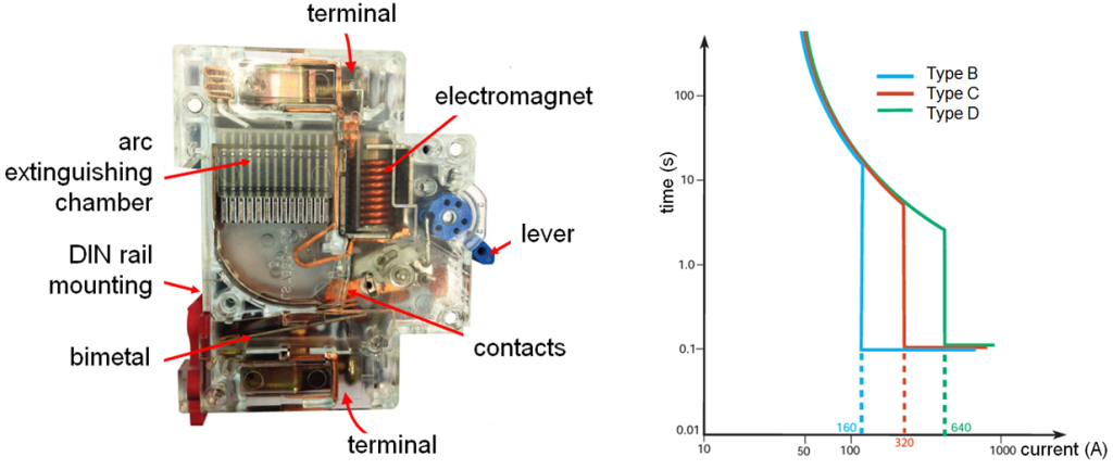
The protective switch, MCB, has two triggers for activating its switch-off mechanism. Switch-on is carried out manually via the lever shift. Behind the lever, the switch position indicator signifies an open or closed state.
The first switch-off trigger is the thermal trigger for monitoring long-term but smaller overload current amounts. This is used to keep the wire’s insulation from melting due to this light current overload. Such an overload occurs when more consumers are connected to some wiring than the built-in wire cross-section permits. A bimetallic element is used for the thermal trigger. A bimetallic element for current breaking can be commonly found in irons, water heaters and various thermostats.
The second switch-off trigger is the magnetic trigger. The flow of fault short circuit current through the coil creates a magnetic field, so an electromagnet is established that attracts the switch-off mechanism. MCBs come in three types: B, C and D. In the field of thermal trigger responsibility, they all act in the same way and time, while at higher short circuit current levels, the characteristics are different. The MCB of type B features a disconnection at 5 In (5 rated currents – commonly used as a household MCB), type C breaks at 10 In (used for transformers and fluorescent lamps) and type D breaks at 20 In (its application is for large motors, transformers and mercury lamps). When a short circuit current of sufficient level for a particular characteristic flows through an MCB, all of the breakers (B,C,D type) are switched off within 100 ms. For the event of a short circuit the planer while projecting should always check the current level flowing through the circuit breaker. This short circuit current must be large enough to strike the magnetic overcurrent trigger in the MCB.
The next and the most important device in the terminal box of the marina for ensuring the protection of indirect and direct contact with live parts using an automatic power switch-off is the Residual Current Device (RCD) switch. The RCD switch was patented for the first time about 90 years ago by Mr Schrack! The most important data for RCD switches are rated current, ‘In’, and the rated (tripping) differential, residual current, ‘IΔn’. One separate RCD switch should be used for each shore terminal box socket.
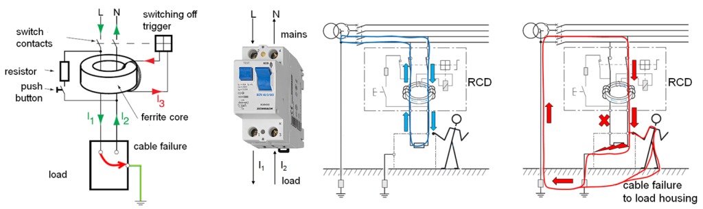
The principle of the RCD switch operation is shown in Figure 4b. It is based on Kirchhoff’s first law, which says that the sum of currents entering the node is equal to the sum of current coming out of it.
Simply stated: the RCD switch looks over the difference in the amount of current that enters through the phase conductor from the utility to the load and the amount of current that leaves the load toward the utility through a neutral conductor. A key component of the RCD switch is the ferrite ring, which is in fact the core of a toroidal transformer. When there is no fault in the load, the sum of the load current passing through the ferrite ring (primary side) is equal to zero, so in the windings around the ferrite ring (secondary side) there is no induced current. In the case of failure, the protective conductor PE (ground) takes over the fault current. There will be, therefore, no current in the neutral conductor. This makes an imbalance. The sum of the currents passing through the ferrite ring is no longer equal to zero. The windings around the ferrite ring induces some current in itself which is further flowing through the electromagnet. The electromagnet attracts the armature so the switch is turned off. A the test button and resistor are available to test the RCD switch. When you press the push button, the RCD switch must turn off the power. The RCD switch can only be used in systems where the neutral and protective conductors are guided separately.
The RCD switch with 30mA–rated residual current should disconnect above fault currents of 15mA, whereby the switch-off time is regularly below 100 ms. However, the RCD switch cannot detect a short circuit in the load. For this the already described MCB is used. The RCD switch reacts only when the current ‘runs’ where it should not ever run (through a metal housing or through a human towards ground)!
Figure 4b – The principle of operation of an RCD switch
Today’s technology enables the realization of a circuit breaker and RCD switch in a single chassis. Such a device is called a combined protective switch. It consolidates all the just-described characteristics of MCB and RCD switches in a single housing. Such a protective device will most likely reside in the terminal boxes for each shore power socket in a marina, as shown in Figure 5.
Figure 5 – Shore connection terminal box
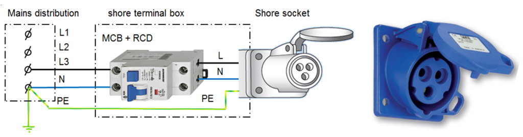
Figure 5a – SCHRACK TECHNIK–designed shore terminal boxes on Vis Island in Croatia
Boat connection
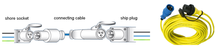
The cable for connecting a ship consists of an industrial cable plug and a three-wire flexible cable that is permanently attached to the ship installation or can be connected via the industrial cable socket on the vessel plug. One contact in the cable plug and cable socket are connected to the protective conductor in the cable (one of three conductors in a three-wire cable). Cable length should not exceed 25 m, and the cable must not have any intermediates at that length.
Figure 6 – Victron connection cable for shore power connection
When the connection on the vessel side is performed using industrial plug, it must be installed in an easily accessible place where no damage could happen, like cable jacking due to ship motion, touching the rope or anchor or crushing with any other moving parts.
Figure 7 – Simple board installation with Victron Energy plug on boat installation
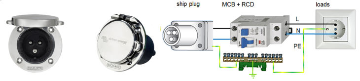
From the input plug on the vessel, the current passes to loads through the MCB and RCD switches, or as explained above, a combined protection switch. A protective earth conductor is connected to the potential equalization rail on board. All metal parts of the ship and electrical devices are also connected by means of separate conductors to the potential equalization rail. The potential equalization rail must be connected to a metal part of the ship which is always in contact with the water around the ship.
Potential equalization of all metal parts with a good grounding-earthing of the potential equalization rail is also one of the basic protection measures against indirect contact with live parts of too-high contact voltage. In the case of any wiring insulation failure affecting the metal housings of any electrical appliance, the same voltage will appear on all interconnected metal parts so there will be no contact voltage as a voltage difference between the conductive parts.
Potential equalization combined with the disconnection of the power source with an overcurrent protection device (MCB) and the disconnection of the power source with a residual current device (RCD) provide sufficient effective protection.
Viewing Figures 5, 6 and 7, one may start to feel safe and secure because all we have said so far is not more complicated than the usual in-house installation. But nature has taken care that when an on-board installation is considered, that is not the end of thinking, but only the right starting point!
The impact of the sea
Metals show their own specific electrical potential characteristics for keeping their own molecules together. This potential varies from metal to metal, as shown in Figure 8.
Figure 8 – Average potential of metals in seawater
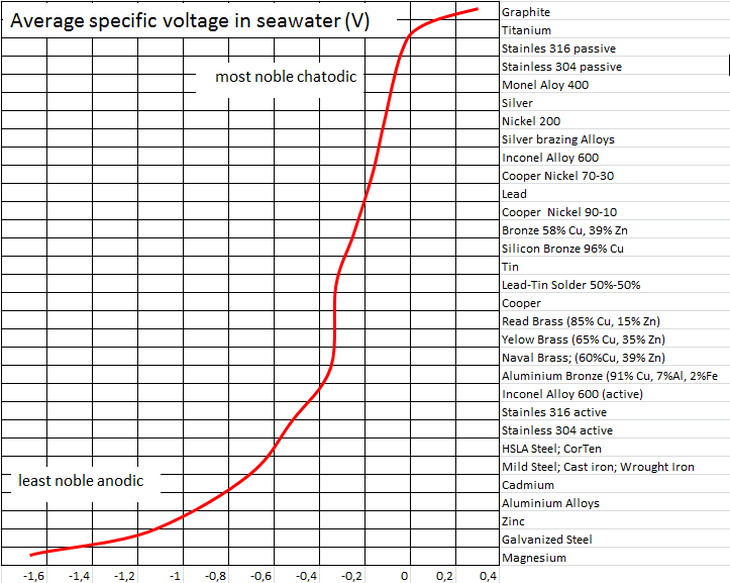
The level of the specific potential of the metal immersed in the sea is shown in Figure 8 and ranges from
-1,6V to + 0,4V. When comparing the potential of two metals to each other, please notice the existence of a potential difference between various metals (for example, zinc has -1,6V and bronze -0,3V). The potential difference of 1,3V is actually the voltage that can drive out electricity.
Immersing various metals in an electrolyte (an electrically conductive liquid), we get a galvanic cell or just more simply said, a battery with a certain voltage. The more negative (less noble) metal is called the anode, and it is the – pole of our battery. Less negative or even positive metal (more noble) is called the cathode, and it is the + pole of our battery. This we know from elementary school when we learned about Volta’s experiment; copper and zinc strips were immersed in sulfuric acid and became a battery with a voltage of 1.1. Recall here also a similar description of a common lead battery working principle.
There will be a potential equalization process if two metals immersed in an electrolyte are in an electrical connection, let say wired or just put electrically together. The negative anode will release a surplus of electrons to flow to the cathode. The flow of electrons, the negative charge carriers, is guided from the minus to the plus side through an electrical connection. We can understand also a positive charge moving from the plus to the minus pole, i.e., from the cathode to the anode. The positive charge flow direction is what is conventionally taken as the ‘official direction of the direct current’. We say current is flowing through the wire from the positive battery pole toward the negative pole. The anode loses electrons and can no longer keep its molecules together. The released parts of the anode are positively charged throughout and are called ions. So in a wire we have a flow of electrons, while in the electrolyte we have flow of ‘ions’. So the circuit is electrically closed and tends to potential equalizing.
This process is a type of electrochemical corrosion and more precisely galvanic corrosion (the galvanic voltage difference of the specific potential of two metals immersed in an electrolyte produces current). The more negative, less noble anode electrode is ‘wasting-corroding’ while at the same time, the less negative, more noble electrode, the cathode, is retained or even becomes coated with parts of anode metal. The anode consumed is called the sacrificial anode. And the whole process of keeping the cathode protected at the expense of a deliberately sacrificed anode is called cathodic corrosion protection.
Figure 9 – Galvanic corrosion and cathodic protection against galvanic corrosion
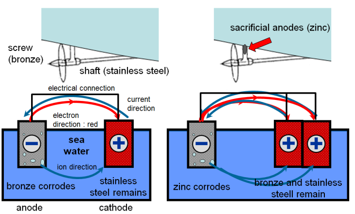
What is going on in an unprotected ship is evident in Figure 9 at the left. Two different metals are electrically connected and immersed in the sea. Due to galvanic corrosion, the bronze is corroding and the stainless steel part is retained. The ship shown on the right side of Figure 9 has a sacrificial anode of zinc. Zinc will corrode, and the bronze and stainless steel remain preserved as intended. Here we can understand the full meaning of the name ’sacrificial‘ anode.
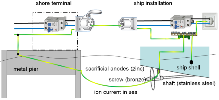
Suppose further that our ship is equipped with sacrificial anodes which are regularly maintained and changed. The size of the sacrificial anode is designed based on the size of the metal surface under the sea that needs protection. But if we get to the dock and simply connect the ship to the shore mains, then the protective conductor makes an electrical connection of dock metal parts and metal parts of the ship. The dock and the ship are in seawater and are electrically connected throughout the protective conductor. That leads to galvanic corrosion where the sacrificial anode protects not only the ship but also the dock metal parts. While protecting the dock, the sacrificial anodes will vanish much quicker than expected, because they are designed only to protect the ship! The situation is shown in Figure 10.
Figure 10 – Why do the sacrificial anodes wear faster? The ship protection anode ‘protects’ the dock
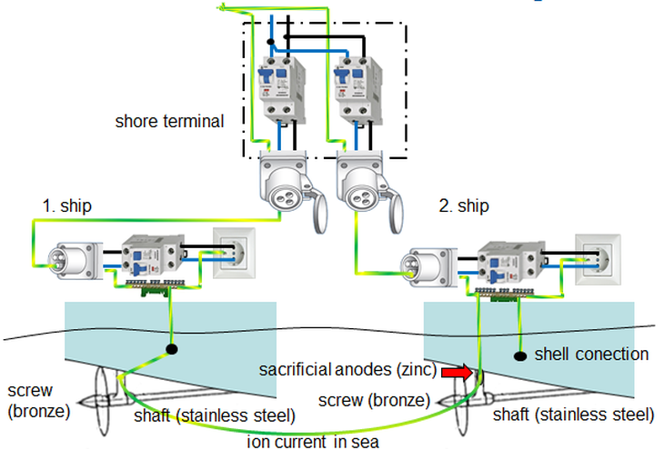
Let’s consider the following situation. Several vessels are connected to the same shore terminal box, as in Figure 11. Their metal parts are connected over the protective conductor too. And now it can happen that your ship (which is protected by sacrificial anodes) also protects the neighbouring unprotected ship with which you are connected via the protective conductor of the shore power connecting cable and shore terminal box installation. So the sacrificial anodes will wear, again, faster than expected. The problem with the rapid wear is not the price of an anode or its replacement, but the fact that when you spend the sacrificial anode, then corrosion starts on the metal with the next most negative potential in the connection; say corrosion of a bronze screw will happen. An ‘eaten’ screw is the last thing you desire when you return the next year to a ship that had wintered in the dock connected to a shore terminal box, let’s say to have the optimal winter battery maintenance .
Figure 11 – Why the sacrificial anode wears faster than expected: ship 2 also ‘protects’ ship 1
How can we avoid this situation of accelerated wear caused by a simple shore electrical connection? Protection of metals from galvanic corrosion can be achieved with external applied voltage of opposite polarity equal to, or greater than, the total amount of the electromotive force of the galvanic cell causing the galvanic corrosion. But all that is not so easy because the connection to the shore introduces an unknown and variable amount of unprotected metal….
The use of galvanic isolators
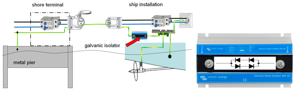
A very practical solution to prevent rapid galvanic corrosion effects due to a connection with the shore mains is shown in Figure 12. A protective earth conductor coming from the ship plug contact should be connected to one terminal of the galvanic isolator. The other terminal of galvanic isolators connects to the potential equalization rail in the ship. A galvanic isolator is an antiparallel combination of two groups of two diodes that are connected in series. Diodes in a galvanic isolator stop the galvanic current in any direction for galvanic voltages up to 1,4 V. This level of 1,4 V is still higher than the galvanic DC voltage level that can occur between the underwater metal of your ship and the underwater pier metal or between the underwater metal of your ship and a neighbouring unprotected ship. Thus, the current circuit for DC galvanic currents (shown in Figures 10 and 11) is interrupted. For higher voltage levels, which are life-threatening, the galvanic isolator is not isolating at all. In that sense the galvanic isolator does not affect the connection between the metal mass of the ship and the shore protective earth. Therefore, the operation of the protective devices in the terminal box on the shore and the protective devices on the boat remain the same, as it should be, namely as it was without the galvanic isolator application!
Figure 12 – Victron galvanic isolator breaks the galvanic current circuit
But what if inside an inexpensive galvanic isolator a single diode is destroyed? If it blows up (has an open circuit), the ship is then naturally further protected from galvanic currents because there is no connection from the ship metal to the pier or neighbouring ship metals. But the whole installation on board remains unconnected with shore earth, which again can be life-threatening! If the diode is short circuited, then there is no more galvanic isolation. Such threats come and exist without any warning, so the galvanic isolator should be checked regularly and especially after each shore socket MCB activation due to any large fault. Furthermore, a galvanic isolator may lose its functionality if a lot of high frequency switch mode power supplies are working on board. We will not try to explain that phenomenon here, but this threat exists too.
The use of an isolating transformer
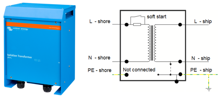
Therefore, the best way of separating a vessel installation from the shore to prevent the galvanic current from flowing, and to keep the highest level of safety for the people on board, is to use an isolating transformer. The isolating transformer transfers 1:1 voltage from the shore, but the transformer secondary circuit is completely separated from the primary circuit, thus providing galvanic isolation. This case is shown in Figure 13. The isolating transformer on the primary side – the shore side – accepts the protective earth conductor, and it is connected to the terminal in the transformer. But this particular input terminal is not connected further! On the secondary side, the side of the ship, one of two terminals the carrying AC voltage of the isolating transformer is grounded on the potential equalization rail. The metal housing of the isolating transformer is also connected with the potential equalization rail.
Figure 13 – Isolation transformer resolves all problems with galvanic currents
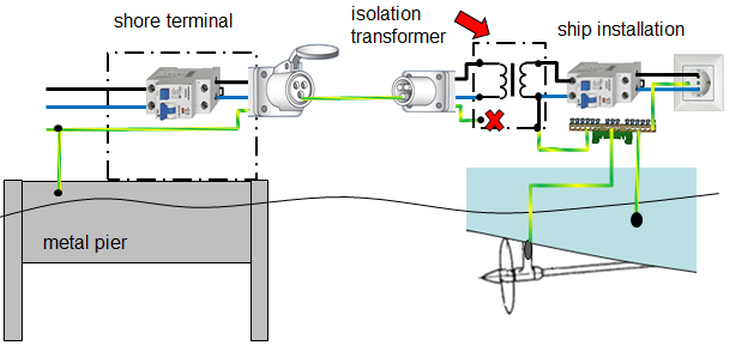
Figure 14 shows an example of a Victron isolation transformer that contains a device for a soft start to prevent the expected short-term increase in current (up to ten times the rated current) when connecting the transformer to the mains. The short-term current increase would almost certainly cause the activation of overload protection devices in the terminal box on the shore. Activation of protective devices is unnecessary because it is not caused by any failure, but by normal behaviour of the transformer during its connection. The unwanted activation of protection devices is prevented by connecting an isolation transformer with the help of the built-in soft start.
Figure 14 – Victron isolation transformer with soft start in close view
Vessel power installation combining two input power sources
What if we have, or want to have, more power sources on the same time?
The parallel operation of, let’s say, an inverter power supply and a shore supply or generator supply at the same time all supplying vessel loads is not allowed. Why? Let’s consider that we have a dual power supply, one from the shore and another from the inverter, both supplying vessel loads at the same time. Then the shore power supply is switched off for a while due to maintenance work on the terminal box. In that case, the ship is back-powering the terminal box on the shore from the inverter, and that may cause an electric shock to the service people working around the terminal box. It is therefore necessary to provide overlapping power sources on board so that only one source is active at a time – either the shore connection or the power from the inverter on board. One such simple solution is shown in Figure 15. It provides that in the case of a power supply from shore, some appliances may be connected to the mains, which are normally not energized while power is coming only from the inverter on the ship. The electric water heater is energized only when the power supply from shore is present, and not during navigation when the ship is battery powered .
Figure 15 – A simple circuit for manual power direction changeover from shore and inverter
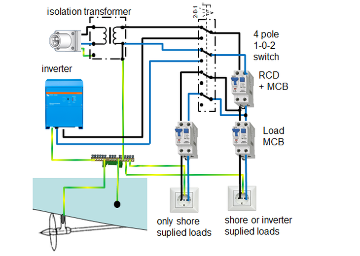
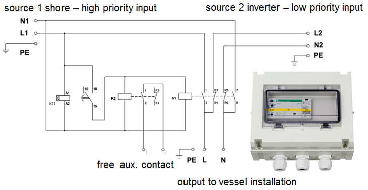
Figure 16 shows the automatic transfer switch. As the wording says, the power is transferred automatically between the two sources, a priority input set having been defined. If the priority input is powered, it will supply the vessel. If the priority input loses power, the switch automatically and immediately switches to the secondary power source. If the primary power comes back again, after some adjustable delay time, the primary power source will supply the vessel again. Both power sources will never supply the vessel at the same time.
Figure 16 – Victron automatic transfer switch
Conclusion
Use this article only as a basic orientation when collecting your own knowledge and researching in this area. If you decide to do boat reconstruction yourself or build a new one, please keep in mind we were not able to say everything we wanted, and we’re not sure that we explained all in a sufficiently clear and precise manner. Please read carefully the Victron and SCHRACK manuals! We did not go into more complicated descriptions of marine corrosion of materials (oak can corrode too), which can worsen if the galvanic voltage is helped with a faulty or damaged DC installation on board through stray currents. We should take a deeper look into the various types of networks – TT, TN and IT – and the operation of MCB and RCD switches in these networks to give a complete picture of operation of these protective devices. We limited this article only to the coastal network type that IEC standards prescribe for marinas, and therefore should be applied in the shore terminal box of the marina (TNS system).
Do not forget that the on-board installation is used by ordinary people. For their safety, please always consult a certified designer or company that deals with on-board installations and has trained and skilled workers.
When you are docking in the marina or pier and want to establish a shore electricity connection to the terminal box, do ask the port service people for a notification paper on the installation in the terminal box. IEC standards stipulate that such a paper must be present to inform you about the terminal box and its built-in protections.
And finally, do not swim at all in the dock and marina, especially not near a boat of that might have an AC installation. A sign should be present prohibiting bathing in a marina, because if the ship installation is incorrect, the sea around the ship may be life-threatening!
Joisp Zdenković
Credits
SCHRACK TECHNIK Ltd of Croatia.
Josip Zdenković – article content, images and translation.
Dalibor Buljan – some picture assistance.


